EP1024280A2 - Collecteur d'admission - Google Patents
Collecteur d'admission Download PDFInfo
- Publication number
- EP1024280A2 EP1024280A2 EP00300205A EP00300205A EP1024280A2 EP 1024280 A2 EP1024280 A2 EP 1024280A2 EP 00300205 A EP00300205 A EP 00300205A EP 00300205 A EP00300205 A EP 00300205A EP 1024280 A2 EP1024280 A2 EP 1024280A2
- Authority
- EP
- European Patent Office
- Prior art keywords
- intake
- blow
- collector
- tubes
- gas passage
- Prior art date
- Legal status (The legal status is an assumption and is not a legal conclusion. Google has not performed a legal analysis and makes no representation as to the accuracy of the status listed.)
- Granted
Links
Images

Classifications
-
- F—MECHANICAL ENGINEERING; LIGHTING; HEATING; WEAPONS; BLASTING
- F02—COMBUSTION ENGINES; HOT-GAS OR COMBUSTION-PRODUCT ENGINE PLANTS
- F02M—SUPPLYING COMBUSTION ENGINES IN GENERAL WITH COMBUSTIBLE MIXTURES OR CONSTITUENTS THEREOF
- F02M35/00—Combustion-air cleaners, air intakes, intake silencers, or induction systems specially adapted for, or arranged on, internal-combustion engines
- F02M35/10—Air intakes; Induction systems
- F02M35/104—Intake manifolds
-
- F—MECHANICAL ENGINEERING; LIGHTING; HEATING; WEAPONS; BLASTING
- F02—COMBUSTION ENGINES; HOT-GAS OR COMBUSTION-PRODUCT ENGINE PLANTS
- F02M—SUPPLYING COMBUSTION ENGINES IN GENERAL WITH COMBUSTIBLE MIXTURES OR CONSTITUENTS THEREOF
- F02M35/00—Combustion-air cleaners, air intakes, intake silencers, or induction systems specially adapted for, or arranged on, internal-combustion engines
- F02M35/10—Air intakes; Induction systems
- F02M35/10209—Fluid connections to the air intake system; their arrangement of pipes, valves or the like
- F02M35/10222—Exhaust gas recirculation [EGR]; Positive crankcase ventilation [PCV]; Additional air admission, lubricant or fuel vapour admission
-
- F—MECHANICAL ENGINEERING; LIGHTING; HEATING; WEAPONS; BLASTING
- F02—COMBUSTION ENGINES; HOT-GAS OR COMBUSTION-PRODUCT ENGINE PLANTS
- F02M—SUPPLYING COMBUSTION ENGINES IN GENERAL WITH COMBUSTIBLE MIXTURES OR CONSTITUENTS THEREOF
- F02M35/00—Combustion-air cleaners, air intakes, intake silencers, or induction systems specially adapted for, or arranged on, internal-combustion engines
- F02M35/10—Air intakes; Induction systems
- F02M35/10091—Air intakes; Induction systems characterised by details of intake ducts: shapes; connections; arrangements
- F02M35/10131—Ducts situated in more than one plane; Ducts of one plane crossing ducts of another plane
-
- F—MECHANICAL ENGINEERING; LIGHTING; HEATING; WEAPONS; BLASTING
- F02—COMBUSTION ENGINES; HOT-GAS OR COMBUSTION-PRODUCT ENGINE PLANTS
- F02M—SUPPLYING COMBUSTION ENGINES IN GENERAL WITH COMBUSTIBLE MIXTURES OR CONSTITUENTS THEREOF
- F02M35/00—Combustion-air cleaners, air intakes, intake silencers, or induction systems specially adapted for, or arranged on, internal-combustion engines
- F02M35/10—Air intakes; Induction systems
- F02M35/104—Intake manifolds
- F02M35/1045—Intake manifolds characterised by the charge distribution between the cylinders/combustion chambers or its homogenisation
-
- F—MECHANICAL ENGINEERING; LIGHTING; HEATING; WEAPONS; BLASTING
- F02—COMBUSTION ENGINES; HOT-GAS OR COMBUSTION-PRODUCT ENGINE PLANTS
- F02M—SUPPLYING COMBUSTION ENGINES IN GENERAL WITH COMBUSTIBLE MIXTURES OR CONSTITUENTS THEREOF
- F02M35/00—Combustion-air cleaners, air intakes, intake silencers, or induction systems specially adapted for, or arranged on, internal-combustion engines
- F02M35/10—Air intakes; Induction systems
- F02M35/10314—Materials for intake systems
- F02M35/10327—Metals; Alloys
-
- F—MECHANICAL ENGINEERING; LIGHTING; HEATING; WEAPONS; BLASTING
- F02—COMBUSTION ENGINES; HOT-GAS OR COMBUSTION-PRODUCT ENGINE PLANTS
- F02M—SUPPLYING COMBUSTION ENGINES IN GENERAL WITH COMBUSTIBLE MIXTURES OR CONSTITUENTS THEREOF
- F02M35/00—Combustion-air cleaners, air intakes, intake silencers, or induction systems specially adapted for, or arranged on, internal-combustion engines
- F02M35/10—Air intakes; Induction systems
- F02M35/1034—Manufacturing and assembling intake systems
- F02M35/10347—Moulding, casting or the like
Definitions
- the present invention relates to an intake manifold for a multi-cylinder engine and particularly, to an improvement in a structure of blow-by-gas passage in the same. It extends to an engine with such a manifold.
- a known intake manifold for a multi-cylinder engine is designed such that intake tubes are bound to groups or a single bundle to avoid interference between intake air flows and to distribute the air-flows uniformly.
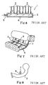
- Such a conventional intake manifold 1 comprises, as shown in Fig. 5, a collector 2 formed by aluminum die casting, a plurality of intake tubes 3 made of aluminum pipes, and an intake tube mount 4 formed by aluminum die casting for fixedly mounting the intake tubes 3 to the engine.
- the intake tubes 3 are bent to desired shapes and joined to the collector 2 and the intake tube mount 4.
- One end of the collector 2 is connected to a blow-by gas tube 5.
- the blow-by gas tube 5 serves to feed back to the engine a mist of blow-by gas (oil mist) which has leaked through gaps at the piston rings to the crank case and contains some lubricant oil (and thus should not be discharged directly to the outside).
- the blow-by gas from the blow-by gas tube 5 is fed via an inner space 6 in the collector 2 to the intake tubes 3 as shown in Fig. 6.
- FIG. 7 Another type of a known intake manifold has a structure shown in Figs. 7 and 8, in which a communicating tube 7 communicates with the intake tubes 3 and is mounted as a branch to intermediate portions of the intake tube 3 for taking a blow-by gas via a tube 8 from the engine.
- the intake tubes 3 and the communicating tube 7 are made of cast iron.
- the communicating tube 7 is joined to the intake tubes 3 by pipes 9.
- the first known type of intake manifold 1 discussed above permits the single blow-by gas tube 5 to be connected to the inner space 6 of a considerable size to which the intake tubes 3 are also connected. This may cause blow-by gas to flow mostly into some of the intake tubes 3 located adjacent to the blow-by gas tube 5. Therefore, only a small amount of blow-by gas flows into the other intake tubes 3 located far from the blow-by gas tube 5, hence hardly providing uniform distribution of the blow-by gas to the intake tubes 3. If the intake manifold 1 includes pipes each connected to their respective intake tube 3 for distributing the blow-by gas uniformly, its construction will be intricate thus increasing the cost.
- the second known type of the intake manifold has the communicating tube 7 mounted to the intermediate portions of the intake tubes 3 and is complicated in the structure. Also, because the communicating tube 7 is joined by the intake tubes 3 by the pipes 9, measures against vibration of the pipes 9 are needed.
- the present invention is intended to eliminate the foregoing problems and its object is to provide an intake manifold capable of distributing blow-by gas to the intake tubes uniformly and easily with the use of a simple construction and without accounting for measures against vibration.
- Through apertures are formed in the blow-by gas passage for communicating the blow-by gas passage with the proximal ends of the intake tubes, thus eliminating the foregoing problems.
- the apertures may be on both sides of the gas passage.
- the intake manifold according to the present invention has the blow-gas passage formed on the surface of the collector and provided with the through apertures to communicate with the intake tubes, whereby the through apertures can easily be machined for having desired cross section and direction. Accordingly, with a simple construction, the distribution of blow-by gas to the cylinders will be uniform due to the corresponding cross sections and directions of the through apertures.
- the blow-by gas passage in the intake manifold of the present invention is formed on the surface of the collector and is thus simple in the construction and requires no measures against vibration.
- the blow-by gas passage may be a ridge on the surface of the collector.
- the manifold may further comprise intake tube mounting rings formed upright on the surface of the collector adjacent to the blow-by gas passage so that the inside of the proximal ends of the intake tubes fitted into the intake tube mounting rings communicates with the through apertures.
- the intake tubes are connected to the collector so that their axes extend across two substantially parallel straight lines and the blow-by gas passage is arranged to extend in parallel to and between the two straight lines and connected at both sides to the intake tubes.
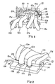
- An intake manifold 10 includes, as shown in Fig. 1, a collector 11 of aluminum die-casting, a plurality of (or four for description) intake tubes 12a, 12b, 12c, and 12d or branches made of aluminum pipes, an intake manifold mount 13 formed by aluminum die-casting, and a blow-by gas passage 14 formed integral with the collector 11 which is a primary feature of the present invention.
- the collector 11 generally has a sheet-like shape and includes bores 15a to 15d, the number of which is the same as the intake tubes 12a to 12d and the diameter of which is adapted to match the outer diameter of the intake tubes 12a to 12d as shown in Fig. 3.
- the bores 15a to 15d are arranged with the first bore 15a and the fourth bore 15d centering across a common line and the second bore 15b and the third bore 15c centering across a common line.
- the two common lines extend in substantially parallel to each other.
- Each of the bores 15a to 15d is accompanied at one end with an intake tube mounting ring 20 that is in an upright position and integral with the collector 11.
- the intake tubes 12a to 12d are closely fitted into the intake tube mounting rings 20.
- the intake tubes 12a to 12d are bent or curved to such shapes as illustrated in Figs. 1 and 2 and are fixedly fitted at one end into the intake tube mounting rings 20 and fixedly joined at the other end to the intake tube mount 13.
- the blow-by gas passage 14 has a narrow, long tube-like shape, as shown in Fig. 2, extending between the common line of the first intake tube 12a and the fourth intake tube 12d and the common line of the second intake tube 12b and the third intake tube 12c.
- the blow-by gas passage 14 is formed integral with the collector 11 to be ridged on a surface of the collector 11 of a sheet-like shape.
- the blow-by gas passage 14 is a passage of a circular shape in the cross section (for example, 12 mm in diameter) and is closed at one end while having a gas inlet 25 at the other end to be connected to a blow-by gas pipe 26.
- the blow-by gas passage 14 is communicated to the intake tubes 12 by through apertures 28 (for example, of an oval shape of 6 mm x 12 mm) provided in interface regions 27 between the blow-by gas passage 14 and the intake tube mounting rings 20 as shown in Figs. 3 and 4.
- the through apertures 28 are machined to have suitable sizes and directions for providing uniform distribution of the blow-by gas to the cylinders of the engine. More particularly, the cross section of the through apertures 28 is smaller on the gas inlet 25 side but greater on the opposite side far from the gas inlet 25.
- the intake manifold 10 is arranged such that blow-by gas passed through the pipe 26 and introduced from the gas inlet 25 to the blow-by gas passage 14 flows through the through apertures 28 that have suitable cross section and the direction.
- the blow-by gas then enters the intake tubes 12a to 12d uniformly before flowing into the cylinders, hence significantly improving the effectiveness of gas distribution to the cylinders.
- blow-by gas passage 14 is ridged on the collector surface, its sides are exposed and can thus be machined easily to have the through apertures 28 of different cross section and direction for achieving uniform distribution of the blow-by gas to the intake tubes 12.
- the intake tube mounting rings 20 are formed upright in proximity to the blow-by gas passage 14, thus allowing the distribution of gas to the cylinders to be changed by either fitting the intake tubes 12 having desired apertures or notches provided in the proximal end thereof to match the through apertures 28 or adjusting the size of apertures or notches in the intake tubes 12.
Landscapes
- Engineering & Computer Science (AREA)
- Chemical & Material Sciences (AREA)
- Combustion & Propulsion (AREA)
- Mechanical Engineering (AREA)
- General Engineering & Computer Science (AREA)
- Lubrication Details And Ventilation Of Internal Combustion Engines (AREA)
Applications Claiming Priority (2)
| Application Number | Priority Date | Filing Date | Title |
|---|---|---|---|
| JP11019056A JP3051391B1 (ja) | 1999-01-27 | 1999-01-27 | インテークマニフォールド |
| JP1905699 | 1999-01-27 |
Publications (3)
| Publication Number | Publication Date |
|---|---|
| EP1024280A2 true EP1024280A2 (fr) | 2000-08-02 |
| EP1024280A3 EP1024280A3 (fr) | 2000-12-06 |
| EP1024280B1 EP1024280B1 (fr) | 2004-12-29 |
Family
ID=11988785
Family Applications (1)
| Application Number | Title | Priority Date | Filing Date |
|---|---|---|---|
| EP00300205A Expired - Lifetime EP1024280B1 (fr) | 1999-01-27 | 2000-01-13 | Collecteur d'admission |
Country Status (6)
| Country | Link |
|---|---|
| US (1) | US6192848B1 (fr) |
| EP (1) | EP1024280B1 (fr) |
| JP (1) | JP3051391B1 (fr) |
| KR (1) | KR100524208B1 (fr) |
| DE (1) | DE60016985T2 (fr) |
| TW (1) | TW424127B (fr) |
Cited By (2)
| Publication number | Priority date | Publication date | Assignee | Title |
|---|---|---|---|---|
| EP1152131A1 (fr) * | 2000-05-05 | 2001-11-07 | Volvo Personvagnar AB | Méthode et dispositif pour la ventilation de gas de carter d'un moteur à combustion interne |
| EP1522714A3 (fr) * | 2003-10-10 | 2010-08-04 | Nissan Motor Company Limited | Dispositif d'admission pour un moteur à combustion interne |
Families Citing this family (17)
| Publication number | Priority date | Publication date | Assignee | Title |
|---|---|---|---|---|
| DE10131004A1 (de) * | 2001-06-27 | 2003-01-09 | Mann & Hummel Filter | Ansaugvorrichtung für eine Brennkraftmaschine mit Kurbelgehäuseentlüftung |
| KR100527441B1 (ko) * | 2002-06-12 | 2005-11-09 | 현대자동차주식회사 | 엔진의 블로 바이 가스 분배장치 |
| JP4059130B2 (ja) * | 2003-04-15 | 2008-03-12 | 日産自動車株式会社 | 内燃機関のブローバイガス還流装置 |
| JP4020058B2 (ja) * | 2003-10-10 | 2007-12-12 | 日産自動車株式会社 | 内燃機関の吸気装置 |
| KR20050047218A (ko) * | 2003-11-17 | 2005-05-20 | 현대자동차주식회사 | 내연기관 엔진의 포지티브 크랭크케이스 벤틸레이션 시스템 |
| JP2005337117A (ja) * | 2004-05-27 | 2005-12-08 | Nissan Motor Co Ltd | エンジンの吸気装置 |
| KR100645576B1 (ko) * | 2004-07-06 | 2006-11-15 | 현대자동차주식회사 | 자동차의 에어 인테이크 시스템 |
| US7441551B2 (en) * | 2005-08-22 | 2008-10-28 | Honda Motor Co., Ltd. | Intake manifold |
| US8020541B2 (en) * | 2009-12-15 | 2011-09-20 | GM Global Technology Operations LLC | Positive crankcase ventilation system |
| KR101234649B1 (ko) * | 2010-11-25 | 2013-02-19 | 현대자동차주식회사 | 2기통 엔진의 pcv결빙 방지 장치 |
| WO2013172192A1 (fr) * | 2012-05-18 | 2013-11-21 | 日産自動車株式会社 | Dispositif d'admission d'air pour moteur à combustion interne |
| JP6053835B2 (ja) * | 2015-01-21 | 2016-12-27 | 本田技研工業株式会社 | ブローバイガス処理装置 |
| CN106321301B (zh) * | 2015-06-30 | 2021-02-02 | 福特环球技术公司 | 曲轴箱强制通风装置及相关发动机总成 |
| JP6656973B2 (ja) * | 2016-03-24 | 2020-03-04 | トヨタ紡織株式会社 | インテークマニホールド |
| JP6881185B2 (ja) * | 2017-09-25 | 2021-06-02 | トヨタ自動車株式会社 | インテークマニホールド |
| JP2019105262A (ja) * | 2017-12-14 | 2019-06-27 | トヨタ自動車株式会社 | ブローバイガス処理装置 |
| CN114251153B (zh) * | 2020-09-24 | 2023-03-10 | 北京汽车动力总成有限公司 | 一种曲通管路结构及车辆 |
Family Cites Families (8)
| Publication number | Priority date | Publication date | Assignee | Title |
|---|---|---|---|---|
| JPS56118519A (en) * | 1980-02-21 | 1981-09-17 | Yamaha Motor Co Ltd | Intake device for engine |
| JPS6285110A (ja) * | 1985-10-11 | 1987-04-18 | Yamaha Motor Co Ltd | V形エンジンのブロ−バイガス回収装置 |
| JPH02107758U (fr) * | 1989-02-14 | 1990-08-28 | ||
| DE4038509A1 (de) * | 1990-12-03 | 1992-06-11 | Mann & Hummel Filter | Ansaugverteiler fuer eine brennkraftmaschine |
| DE4313091A1 (de) * | 1993-04-22 | 1994-10-27 | Bischoff Erhardt Gmbh Co Kg | Flansch zur Befestigung von Rohren |
| US5813375A (en) * | 1996-03-11 | 1998-09-29 | Siemenselectric Limited | Method and system for distributing vapors or gases to each cylinder of a multicylinder engine |
| JPH11117722A (ja) * | 1997-10-20 | 1999-04-27 | Honda Motor Co Ltd | ブローバイガス還流装置 |
| US6089199A (en) * | 1999-03-01 | 2000-07-18 | Ford Global Technologies, Inc. | Air cleaner module having integrated engine valve cover |
-
1999
- 1999-01-27 JP JP11019056A patent/JP3051391B1/ja not_active Expired - Fee Related
- 1999-12-30 KR KR10-1999-0065771A patent/KR100524208B1/ko not_active Expired - Fee Related
-
2000
- 2000-01-06 TW TW089100151A patent/TW424127B/zh not_active IP Right Cessation
- 2000-01-13 DE DE60016985T patent/DE60016985T2/de not_active Expired - Lifetime
- 2000-01-13 EP EP00300205A patent/EP1024280B1/fr not_active Expired - Lifetime
- 2000-01-14 US US09/482,325 patent/US6192848B1/en not_active Expired - Lifetime
Cited By (3)
| Publication number | Priority date | Publication date | Assignee | Title |
|---|---|---|---|---|
| EP1152131A1 (fr) * | 2000-05-05 | 2001-11-07 | Volvo Personvagnar AB | Méthode et dispositif pour la ventilation de gas de carter d'un moteur à combustion interne |
| US6966310B2 (en) | 2000-05-05 | 2005-11-22 | Volvo Personvagnar Ab | Method and device for ventilation of gases in a combustion engine |
| EP1522714A3 (fr) * | 2003-10-10 | 2010-08-04 | Nissan Motor Company Limited | Dispositif d'admission pour un moteur à combustion interne |
Also Published As
| Publication number | Publication date |
|---|---|
| JP3051391B1 (ja) | 2000-06-12 |
| US6192848B1 (en) | 2001-02-27 |
| KR100524208B1 (ko) | 2005-10-26 |
| JP2000220536A (ja) | 2000-08-08 |
| DE60016985D1 (de) | 2005-02-03 |
| EP1024280B1 (fr) | 2004-12-29 |
| TW424127B (en) | 2001-03-01 |
| EP1024280A3 (fr) | 2000-12-06 |
| DE60016985T2 (de) | 2005-12-29 |
| KR20000052626A (ko) | 2000-08-25 |
Similar Documents
| Publication | Publication Date | Title |
|---|---|---|
| US6192848B1 (en) | Intake manifold | |
| US4577596A (en) | Intake manifold structure for a V-type internal combustion engine | |
| US8161950B2 (en) | Exhaust gas recirculating device for internal combustion engines | |
| WO2000043660A1 (fr) | Cylindre pour moteur a combustion interne | |
| EP0208461B1 (fr) | Moteur à combustion interne | |
| JP2892700B2 (ja) | V形エンジンの吸気装置 | |
| GB2228046A (en) | I.c. engine intake manifold | |
| JPH03913A (ja) | 凹部を設けた吸気マニフォールドを備えた内燃機関 | |
| JP4045630B2 (ja) | エンジンの吸気装置 | |
| USRE43734E1 (en) | V-type engine air intake device | |
| JP2009047110A (ja) | 内燃機関 | |
| JP2013007360A (ja) | 内燃機関の吸気装置 | |
| US3832983A (en) | Cylinder head for an internal combustion engine | |
| JP2001525513A (ja) | ポンプノズルユニットを備えた内燃機関用シリンダヘッド | |
| US5476077A (en) | Thermostat-mounting position structure | |
| US6363717B1 (en) | Exhaust gas duct cooled with water | |
| MXPA00000763A (es) | Colector de admision | |
| JPH08284767A (ja) | V型多気筒エンジンの吸気装置 | |
| JP4933224B2 (ja) | 潤滑系と冷却系と始動系を備えた内燃機関 | |
| CN1605743B (zh) | 用于内燃机的进气装置 | |
| EP0939211A2 (fr) | Collecteur d'admission du type à résonance pour moteur à plusieurs cylindres | |
| US3802399A (en) | Air inlet arrangement in four-cycle engine | |
| US11047334B2 (en) | Intake chamber air diffusing feature in an opposed-piston engine | |
| JPH0746768Y2 (ja) | 多気筒内燃機関における吸気装置 | |
| EP1101921A3 (fr) | Culasse pour un moteur à combustion interne avec plusieurs cylindres rangés en ligne , avec un système d'admission de l'air secondaire |
Legal Events
| Date | Code | Title | Description |
|---|---|---|---|
| PUAI | Public reference made under article 153(3) epc to a published international application that has entered the european phase |
Free format text: ORIGINAL CODE: 0009012 |
|
| AK | Designated contracting states |
Kind code of ref document: A2 Designated state(s): DE FR GB |
|
| AX | Request for extension of the european patent |
Free format text: AL;LT;LV;MK;RO;SI |
|
| PUAL | Search report despatched |
Free format text: ORIGINAL CODE: 0009013 |
|
| AK | Designated contracting states |
Kind code of ref document: A3 Designated state(s): AT BE CH CY DE DK ES FI FR GB GR IE IT LI LU MC NL PT SE |
|
| AX | Request for extension of the european patent |
Free format text: AL;LT;LV;MK;RO;SI |
|
| 17P | Request for examination filed |
Effective date: 20010306 |
|
| AKX | Designation fees paid |
Free format text: DE FR GB |
|
| 17Q | First examination report despatched |
Effective date: 20040219 |
|
| GRAP | Despatch of communication of intention to grant a patent |
Free format text: ORIGINAL CODE: EPIDOSNIGR1 |
|
| GRAS | Grant fee paid |
Free format text: ORIGINAL CODE: EPIDOSNIGR3 |
|
| GRAA | (expected) grant |
Free format text: ORIGINAL CODE: 0009210 |
|
| AK | Designated contracting states |
Kind code of ref document: B1 Designated state(s): DE FR GB |
|
| REG | Reference to a national code |
Ref country code: GB Ref legal event code: FG4D |
|
| REF | Corresponds to: |
Ref document number: 60016985 Country of ref document: DE Date of ref document: 20050203 Kind code of ref document: P |
|
| PLBE | No opposition filed within time limit |
Free format text: ORIGINAL CODE: 0009261 |
|
| STAA | Information on the status of an ep patent application or granted ep patent |
Free format text: STATUS: NO OPPOSITION FILED WITHIN TIME LIMIT |
|
| ET | Fr: translation filed | ||
| 26N | No opposition filed |
Effective date: 20050930 |
|
| REG | Reference to a national code |
Ref country code: GB Ref legal event code: 746 Effective date: 20071227 |
|
| REG | Reference to a national code |
Ref country code: GB Ref legal event code: 732E Free format text: REGISTERED BETWEEN 20090618 AND 20090624 |
|
| REG | Reference to a national code |
Ref country code: FR Ref legal event code: TP |
|
| REG | Reference to a national code |
Ref country code: FR Ref legal event code: PLFP Year of fee payment: 17 |
|
| REG | Reference to a national code |
Ref country code: FR Ref legal event code: PLFP Year of fee payment: 18 |
|
| REG | Reference to a national code |
Ref country code: FR Ref legal event code: PLFP Year of fee payment: 19 |
|
| PGFP | Annual fee paid to national office [announced via postgrant information from national office to epo] |
Ref country code: FR Payment date: 20190123 Year of fee payment: 20 Ref country code: GB Payment date: 20190121 Year of fee payment: 20 Ref country code: DE Payment date: 20190123 Year of fee payment: 20 |
|
| PGFP | Annual fee paid to national office [announced via postgrant information from national office to epo] |
Ref country code: DE Payment date: 20190123 Year of fee payment: 20 |
|
| REG | Reference to a national code |
Ref country code: DE Ref legal event code: R071 Ref document number: 60016985 Country of ref document: DE |
|
| REG | Reference to a national code |
Ref country code: GB Ref legal event code: PE20 Expiry date: 20200112 |
|
| PG25 | Lapsed in a contracting state [announced via postgrant information from national office to epo] |
Ref country code: GB Free format text: LAPSE BECAUSE OF EXPIRATION OF PROTECTION Effective date: 20200112 |