EP1024338A2 - Dispositif d'alimentation en munitions pour cartouches sans bande - Google Patents
Dispositif d'alimentation en munitions pour cartouches sans bande Download PDFInfo
- Publication number
- EP1024338A2 EP1024338A2 EP00101369A EP00101369A EP1024338A2 EP 1024338 A2 EP1024338 A2 EP 1024338A2 EP 00101369 A EP00101369 A EP 00101369A EP 00101369 A EP00101369 A EP 00101369A EP 1024338 A2 EP1024338 A2 EP 1024338A2
- Authority
- EP
- European Patent Office
- Prior art keywords
- ammunition
- chain
- feeder according
- tensioning
- ratchet wheel
- Prior art date
- Legal status (The legal status is an assumption and is not a legal conclusion. Google has not performed a legal analysis and makes no representation as to the accuracy of the status listed.)
- Granted
Links
- 230000007246 mechanism Effects 0.000 title description 8
- 230000033001 locomotion Effects 0.000 claims description 51
- 230000001133 acceleration Effects 0.000 description 17
- 239000000463 material Substances 0.000 description 8
- 230000000694 effects Effects 0.000 description 5
- 230000000903 blocking effect Effects 0.000 description 4
- 230000005540 biological transmission Effects 0.000 description 2
- 238000010304 firing Methods 0.000 description 2
- 238000004519 manufacturing process Methods 0.000 description 2
- 229910000831 Steel Inorganic materials 0.000 description 1
- 230000009471 action Effects 0.000 description 1
- XAGFODPZIPBFFR-UHFFFAOYSA-N aluminium Chemical compound [Al] XAGFODPZIPBFFR-UHFFFAOYSA-N 0.000 description 1
- 229910052782 aluminium Inorganic materials 0.000 description 1
- 230000008859 change Effects 0.000 description 1
- 239000003795 chemical substances by application Substances 0.000 description 1
- 238000010276 construction Methods 0.000 description 1
- 230000008878 coupling Effects 0.000 description 1
- 238000010168 coupling process Methods 0.000 description 1
- 238000005859 coupling reaction Methods 0.000 description 1
- 230000001419 dependent effect Effects 0.000 description 1
- 239000012530 fluid Substances 0.000 description 1
- 238000007373 indentation Methods 0.000 description 1
- VNWKTOKETHGBQD-UHFFFAOYSA-N methane Chemical class C VNWKTOKETHGBQD-UHFFFAOYSA-N 0.000 description 1
- 239000004033 plastic Substances 0.000 description 1
- 229920003023 plastic Polymers 0.000 description 1
- 238000004904 shortening Methods 0.000 description 1
- 238000004513 sizing Methods 0.000 description 1
- 239000010959 steel Substances 0.000 description 1
- 238000003860 storage Methods 0.000 description 1
- 238000009423 ventilation Methods 0.000 description 1
Images


Classifications
-
- F—MECHANICAL ENGINEERING; LIGHTING; HEATING; WEAPONS; BLASTING
- F41—WEAPONS
- F41A—FUNCTIONAL FEATURES OR DETAILS COMMON TO BOTH SMALLARMS AND ORDNANCE, e.g. CANNONS; MOUNTINGS FOR SMALLARMS OR ORDNANCE
- F41A9/00—Feeding or loading of ammunition; Magazines; Guiding means for the extracting of cartridges
- F41A9/61—Magazines
- F41A9/64—Magazines for unbelted ammunition
- F41A9/76—Magazines having an endless-chain conveyor
-
- F—MECHANICAL ENGINEERING; LIGHTING; HEATING; WEAPONS; BLASTING
- F41—WEAPONS
- F41A—FUNCTIONAL FEATURES OR DETAILS COMMON TO BOTH SMALLARMS AND ORDNANCE, e.g. CANNONS; MOUNTINGS FOR SMALLARMS OR ORDNANCE
- F41A9/00—Feeding or loading of ammunition; Magazines; Guiding means for the extracting of cartridges
- F41A9/01—Feeding of unbelted ammunition
- F41A9/04—Feeding of unbelted ammunition using endless-chain belts carrying a plurality of ammunition
-
- F—MECHANICAL ENGINEERING; LIGHTING; HEATING; WEAPONS; BLASTING
- F41—WEAPONS
- F41A—FUNCTIONAL FEATURES OR DETAILS COMMON TO BOTH SMALLARMS AND ORDNANCE, e.g. CANNONS; MOUNTINGS FOR SMALLARMS OR ORDNANCE
- F41A9/00—Feeding or loading of ammunition; Magazines; Guiding means for the extracting of cartridges
- F41A9/61—Magazines
- F41A9/79—Magazines for belted ammunition
- F41A9/81—Magazines for belted ammunition having provision for collecting belt links or empty cartridge cases
Definitions
- the invention relates to an ammunition supply device for feeding beltless ammunition in a particular self-retracting firearm, with an endless guided ammunition supply chain for feeding ammunition in the firearm, at least two deflection units for Guide the ammunition supply chain, and a drive to intermittently driving one of the deflection units to the gun ammunition intermittently in the ammunition feed direction feed.
- Such an ammunition supply device is known from US Pat. No. 4,573,395 known.
- This publication also shows a coupled to the ammunition feeder Ammunition magazine with an ammunition guide chain.
- a short loop of the ammunition chain is from the movement of the rest of the ammunition chain uncoupled by two loops of this Arranged parallel to each other via a loop
- the rocker is forcibly coupled in the conveying direction of the ammunition guide chain are guided.
- a disadvantage of the known ammunition feeders is as follows.
- the ammunition feed movement is common intermittent, d. H. short rapid accelerations occur and a subsequent standstill.
- the Firearm usually serves as a drive for both that Ammunition supply chain, as well as for one between one Ammunition magazine and the ammunition feeder working Transfer device and for the ammunition guide chain in the ammunition magazine. So the whole accelerated inertial mass of these units with each shot and then slowed down again.
- the ammunition supply chain the ammunition feeder is however in somewhat elastic and effected by appropriate Restoring forces a reciprocating rotary motion the non-driven deflection unit, the transfer device as well as the ammunition guide chain in the ammunition magazine.
- the latter have units a large inertial mass, so that the acceleration and braking forces at the corresponding back and forth Movement are correspondingly large.
- the non-driven deflection unit moves in the opposite direction the direction of ammunition feed, the drive of the driven Deflection unit at the next acceleration apply (the next shot) a great force (energy) around this taking place in the opposite direction First slow down the movement and then into the correct one Accelerate direction.
- the drive of the deflection unit should be disproportionately trained, so that he can apply this acceleration. Further the ammunition supply chain is unnecessarily heavily loaded and must therefore be suitably strong.
- the invention has for its object a ammunition feeder of the type mentioned above to develop that from the drive of the ammunition supply chain acceleration forces to be applied constant operating speeds of the ammunition supply chain can be reduced.
- the invention solves this problem with an ammunition supply device of the type mentioned above with the characteristic Features of claim 1.
- the at least one non-driven deflection unit coupled with a locking device which a Movement of the deflection unit against the ammunition feed direction locks.
- the locking device has an advantageous effect that is, on the non-driven deflection unit such that, in the worst case, such in opposite Movement taking place not slowed down must be, but always from a standstill (or movement in the ammunition feed direction) of the ammunition supply chain can be started.
- the powered The entire system therefore only needs to be deflected in Accelerate the feed direction and not as previously described first slow down.
- the drive can thus be advantageous the driven deflection unit is dimensioned weaker his. They are also on the ammunition supply chain acting loads lower.
- the ammunition feeder can also be used for conveying and Save other items can be used.
- Locking device are suitable for all devices allow rotation in one direction and in the block others. For example, a ratchet mechanism, etc. are used.
- the coupling of the non-driven deflection unit with the locking device can, if necessary, have one with the latter Conveyor shaft connected in a form-fitting manner, this deflection unit but can also the locking device directly exhibit, etc.
- the blocking also includes the completely rigid locking also a strong braking or blocking the movement only after one has been covered short movement distance against the ammunition feed direction. However, this movement is preferred rigidly locked.
- a ratchet mechanism locks, for example, only after discrete, not arbitrarily small changes in the angle of rotation, which correspond to the distances between the individual ratchets correspond to each other. Within this angle of rotation change is a rotation in both Directions possible. This is no longer the case with freewheeling the case.
- the locking device is preferred formed such that their counter to the ammunition feed direction acting lock is releasable (claim 3).
- the locking device has a particularly space-saving solution preferably already an adjustment means for adjustment the position of the ammunition supply chain in the ammunition supply direction on what, for example, after loading of the attached ammunition magazine can (claim 4).
- this has an externally operable Worm spindle and a non-positive with the non-driven deflection unit coupled gear ring on, with the worm spindle in the ring gear intervenes (claim 5).
- the release mechanism of the locking device is rigid coupled with a ratchet wheel into which an associated Locking cylinder engages, the locking cylinder so with respect the ratchet wheel is arranged that it is a movement of the ratchet wheel locks when the ammunition supply chain moved against the ammunition feed direction will (claim 6).
- the locking cylinder is preferred trained so that he also the ratchet movement of the ammunition supply chain in the ammunition supply direction blocks (claim 7).
- the locking cylinder as a cylindrical pin with a flat end face engaging in the ratchet wheel trained the eccentric with the ratchet can be releasably engaged (claim 8).
- a means is provided which the locking cylinder in a defined engagement position brings in the ratchet wheel (claim 9).
- This is preferred Medium a spring-supported cylindrical pin with hemispherical engaging in the ratchet wheel End face (claim 10).
- the non-driven deflection unit is preferably included a transfer device coupled for the exchange of ammunition or ammunition remnants with one to the Ammunition feeder coupled ammunition magazine is designed, the movements of another in the Ammunition magazine provided ammunition guide chain and the ammunition supply chain are coupled (claim 11). Thanks to the invention, these are also advantageous coupled movement of several ammunition conveyors Floats suppressed.
- the ammunition supply device preferably has at least a chain tensioning means for tensioning the ammunition guide chain and / or the ammunition supply chain with a predetermined chain tension, the chain tensioning means to increase the respective chain tension Clamping movement in the clamping direction and to lower the Chain tension a tension movement against the tension direction performs, and the chain tensioning means an agent has to influence the spring constant of the chain tensioning device depending on the clamping direction and the speed the clamping movement (claim 12).
- Advantageous can with this measure the most diverse movement situations the ammunition guide chain (thermal conditional material expansion, acceleration or deceleration, etc.), which in turn influences the tensioning movement of the Chain tensioners have to be taken into account, such that in particular a lot in the ammunition chain is avoided if possible.
- FIG. 1 an ammunition magazine 2 is shown, in which a endless ammunition guide chain 6 cartridges 4 (e.g. in the direction of funding A).
- the ammunition chain 6 consists of two highly tear-resistant parallel guided transport chains, the distance between them in corresponds essentially to the cartridge length. In constant The distance between the two parallel transport chains is over Cross bars 8 connected to each other. The distance between the crossbars 8 from each other is substantially equal to the cartridge diameter plus the diameter of a cross bar 8 and a certain scope for freedom of movement of the guided cartridges 4.
- the endless ammunition guide chain thus formed 6 is in several loops over pulleys 10, 12, 14 and 16 by the one shown in FIG Section of the ammunition magazine 2 out.
- the cartridges 4 are inside the ammunition magazine 2 guided in guideways 18 with little clearance, which, for example, with sliding / roller tracks made of low-wear Plastics are provided.
- the rigid, thin Cross bars 8 separate two successive ones Cartridges or their sleeves from each other and promote them through the guideway 18 in the ammunition magazine 2.
- the crossbars 8 can be adapted to the cartridge shape Have profile with which tilting of the cartridges 4th is avoided if possible. Furthermore, the cross bars 8 axially rotatable on the two chains of the ammunition guide chain 6 attached to the unrolling of the cartridges 4 within the guideway 18 and thus also on to facilitate the crossbars 8.
- the cartridges are over a feed wheel 20 and transfer wheels 22 and 24 to an ammunition feeder 25 handed over.
- the ammunition feeder 25 has an ammunition supply chain 26 on that in an endless loop around a first 28 and a second 30 pulley is guided and several successive bowl-shaped receptacle 32 forms.
- the receptacles 32 are dimensioned so that they can each hold a cartridge 4.
- the ammunition supply chain 26 is in turn within a guideway 34 performed.
- a self-retracting firearm may be provided, which the cartridges fed from the ammunition supply chain 26 takes over, shoots and the empty cartridge cases in turn passes to the ammunition supply chain 26.
- cartridges 4 are thus removed from the ammunition guide chain 6 in the conveying direction A to the feed wheel 20 transported, from there forcibly over the Transfer wheel 22 to a corresponding receptacle 32 passed to the ammunition supply chain 26 while simultaneously one - seen in feed direction B - further forward lying cartridge on the second guide roller 30 of one Firearm, not shown, is loaded.
- the empty cartridge cases are also on the pulleys 16 and 12 transported further.
- the feed wheel 20 and the two transfer wheels 22 and 24 are positively connected to the first deflection roller 28, so that the attacking over the second pulley 30 Firearm retraction the ammunition supply chain 26, the first pulley 28, the two Transfer wheels 22 and 24, the feed wheel 20 and also the Ammunition guide chain 6 drives.
- the feed wheel 20 can have a large connection angle range the ammunition supply chain 26 to the ammunition magazine 2 be covered.
- Each loop of the ammunition guide chain 6 forming first and second deflecting rollers 14 and 16 are in Direction of conveyance A of the ammunition guide chain 6 is displaceable arranged. For this, reference is made to FIG. 2.
- Fig. 2 shows a schematic side view of the in Fig. 1 shown ammunition magazine 2.
- the first Carriage 40 is over rollers 44 and 46 in the first Link rail 36 guided and carries the Axis of the first deflection roller 14.
- the second is also Carriage 42 over rollers 48 and 50 in the second link rail 38 guided and carries the axis the second deflection roller 16.
- On the first carriage 40 the end of a first linkage 52 is pivotally attached, the other end with the first end of a seesaw 54 is pivotally connected.
- the end is one second linkage 56 pivotable on the second carriage 42 attached while the second end of the second linkage 56 can be pivoted with the second end of the rocker 54 connected is.
- the rocker 54 in turn is over one Pivot axis 58 is displaceable in a further link rail 60 guided.
- the ammunition guide chain 6 via the sliding rocker 54, the two linkages 52 and 56, the two slides 40 and 42 and the two deflection rollers 14 and 16 either tensioned or be relaxed.
- the firearm can feed wheel 20 drive, intermittently in the launch stroke of the Cartridges.
- the ammunition chain 6 accelerated strongly initially and then slowed down again.
- Tensile forces due to their inertial mass due to the numerous existing cartridges is very high.
- This traction during the rocker 54 compensates for the acceleration phase, by the first deflection roller 14 during acceleration in the embodiment shown in FIG is moved to the right, whereby only the one between the feed wheel 20 and the first deflection roller 14 Section of the ammunition guide chain 6 accelerated must become.
- Between the feed wheel 20 and the second deflection roller 16 would also create lots in the ammunition chain 6 arise, which, however, by the seesaw 54 is compensated.
- the first deflection roller is moving 14 to the right in FIG. 1, i. H. the mobile Carriage 40 to the left in FIG. 2, so the Carriage 42 of rocker 54 is forcibly shown in FIG. 2 moved to the right, which in turn is a movement of the second Deflection roller 16 means in Fig. 1 to the left.
- a rocker 54 mounted in a fixed position would thus be the the shortening of the loop shown in Fig. 1 between Feed wheel 20 and first guide roller 14 resulting lots between feed wheel 20 and second deflection roller 16 exactly canceled.
- a toothed segment 62 is rigidly connected to the rocker 54, in which a gear 64 engages.
- the gear 64 is actuated
- the potentiometer 68 is one as a bridge branch Wheatstone bridge, not shown, switched, whose other bridge branch consists of two series connected There is resistance.
- This output signal one is positively connected to the deflection roller 10 Drive (not shown) supplied. The drive is controlled so that he try to rocker 54th to pivot back to the rest or zero position.
- Deflection roller 10 is the firearm generated intermittent movement of the ammunition supply chain 26 and the feed wheel 20 in a possible smooth movement of the ammunition guide chain 6 converted.
- 3 and 3a show a cross section through the ammunition magazine 2.
- the cut is made through a central surface along the link rail 60 of the rocker 54.
- the rocker 54 is on provided on both side surfaces of the ammunition magazine 2.
- the respective pivot axis 58 of the rocker 54 is in one Cross bridge 70 mounted, which the two rockers 54 with each other connects.
- the cross bridge 70 is inside the link rails 60 slidable on both sides guided.
- a chain tension spring 72 provided on both sides acts between the rigid housing of the ammunition magazine 2 and the displaceably guided cross bridge 70. This is the Chain tension spring 72 in a rigid with the housing of the Ammunition magazine 2 connected spring guide cylinder 74 held while their free moving end over one Spring guide rod 76 presses against the cross bridge 70. All in all the chain tension spring 72 presses the entire rocker 54 in the embodiment shown in FIG. 2 to the right, whereby the two shown in Fig. 1 Deflection rollers 14 and 16 also pushed to the right become. As a result, the ammunition guide chain 6 with pre-tensioned a certain predetermined chain tension. The chain tension results from the spring constant the chain tension spring 72 and its engagement position. The linear applies to ordinary spiral springs Hook's law on wide areas of the engagement position.
- the spring constant of the chain tension spring 72 to increase so much that such a case essentially can be excluded does not lead to the goal here. With large spring constants, this is from the chain tension spring 72 clamping force already exerted after engagement the same over a short distance so strong that the ammunition guide chain 6 is unnecessarily tense, whereby Management problems and material fatigue occur can. Such a short distance indentation of the chain tension spring But 72 can already, for example thermally induced material strains are caused, because different materials for the housing of the ammunition magazine 2 (aluminum, carbon fiber composites, etc.) and the ammunition guide chain 6 (steel, etc.) be used. In this respect, the spring constant of the Chain tension spring 72 can be chosen so that even at strong temperature changes and the associated Engaging and disengaging movements from the chain tension spring 72 tension force exerted on the ammunition guide chain 6 stays in reasonable areas.
- a hydraulic cylinder 78 is provided, the cylinder of which is rigid with the spring guide cylinder 74 connected is.
- a Piston 80 parallel to the direction of action of the chain tension spring 72 out.
- a piston rod 82 of the piston 80 is via a T-groove 84 with the cross bridge 70 non-positively connected.
- a ball check valve 86 provided that when the Piston 80 closes in the cylinder, the closing movement is essentially caused by a spring means.
- the ball check valve opens 86 due to the ventilation duct of the Ball check valve 86 flowing hydraulic fluid in the hydraulic cylinder 78.
- the hydraulic cylinder 78 is dimensioned so that that he quickly engages his piston 80 opposes an essentially infinite resistance. Blocked with such a rapid engagement movement the hydraulic cylinder 78 thus via the piston rod 82 the movement of the cross bridge 70 in the in FIG. 3 illustrated embodiment to the left. A rapid movement of the cross bridge 70 to the left occurs as executed above in the event that the feed wheel 20 the Ammunition chain 6 accelerates.
- the hydraulic Cylinder 78 therefore increases the spring constants in total the chain tension spring 72 to a value of almost infinite. This corresponds to the case that the cross bridge 70 or the rocker 54 rigid with the housing of the ammunition magazine 2 is connected.
- a chain adjustment means 90 is also shown, that on the feed wheel 20 or the first deflecting roller 28 works.
- the chain adjustment means 90 has a pivotable Worm gear 92 on that by a drive shaft stub 94 can be operated from.
- On the axis of the Feed wheel 20 or the first deflection roller is rigid Gear ring 96 attached to the outside of the housing into which the swiveled Worm gear 92 can intervene. Consequently can the position of the ammunition guide chain 6 by means of Turning the worm gear 92, which in the pivoted Condition the ring gear 96 and thus the feed wheel 20 or the first deflection roller 28 rotates.
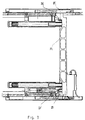
- Fig. 4 shows a plan view of a freewheel with detachable Lock for the first pulley 28.
- the first deflection roller is decelerated accordingly 28 from the second deflection roller 30 via the ammunition supply chain 26 driven.
- the second pulley is located between the shots 30 silent while the ammunition supply chain 26 due to their inert mass and the restoring forces cannot immediately go to sleep.
- the upset or stretched chain sections cause restoring forces in the ammunition supply chain 26 which the first deflection roller 28 to a reciprocating Bring rotation.
- the Ammunition supply chain 26 on the cartridge supply side in the feed direction B accelerates, so it can be the worst Case that the guide roller 28 just one Performs rotational movement in the opposite direction.
- the guide roller 28 moves a large inert mass.
- This inert mass must now be driven by the Deflection roller 30 are overcome so that the first Deflection roller 28 first braked and then in a Rotary movement brought in the direction of feed B. becomes.
- the drive of the guide roller 30 in accelerate a very large mass in this case this drive must be disproportionately large and the ammunition supply chain 26 would be disproportionate should be highly resilient.
- the first deflection roller 28 is rigidly coupled to a freewheel 119 (see also Figure 2), the rotational movement of the first deflection roller 28 against the feed direction B locks. Thanks to this freewheel 119, no acceleration the deflection roller 28 and the units coupled therewith occur more against the feed direction B, so that the drive of the second deflection roller 30 always only the total inertial mass of the ammunition supply chain 26 accelerate, but does not have to slow down first.
- the drive always turns the second deflection roller 30 into one brings predetermined location, which, for example, by the Firing mechanism of a self-retracting firearm is now determined by the extension of the ammunition supply chain 26 on the cartridge feed path and the associated restoring force the first deflection roller 28 then rotated so far in the feed direction B that the ammunition supply chain 26 on the cartridge supply side is slightly compressed.
- This has a subsequent acceleration the second deflection roller 30 in total less force to apply because of this acceleration positively biased ammunition supply chain 26 one Put part of your chain tension in the acceleration can.
- the chain part on the cartridge case discharge track is stretched to the same extent as the one Part is compressed on the cartridge feed side. In order to but face such on both lanes through the Ammunition supply chain 26 caused resetting forces, that the acceleration by the second pulley 30th is supported.
- the freewheel 119 is not explained in more detail below. because its function and structure from the state of the art is well known. Otherwise, for the Freewheel 119 any other suitable type of locking means are used, the rotation of the first pulley 28 allowed in one direction and in the other Direction essentially (preferably rigid) blocks.
- the freewheel 119 If the freewheel 119 is used as the blocking means, then its locking effect in one direction of rotation in principle not easily solvable. To the free wheel 119 to allow this blocking effect to be released anyway the freewheel 119 with an additional releasable lock coupled, which is explained in more detail below with reference to FIG. 4 becomes.
- Fig. 4 shows such a releasable lock with the Freewheel 119 is non-positively coupled.
- the freewheel sits in a ratchet wheel 102 and is rigid coupled to the first deflection roller 28.
- a housing 115 this releasable lock has one in engagement with the Pawls of the ratchet wheel 102 standing locking cylinder 108 on.
- the locking cylinder 108 has a flat end face on, when disengaged by an eccentric shaft 112 Lock cylinder 108 on the steep flanks of the pawls Pawl wheel 102 strikes. This will turn the Pawl wheel 102 in the embodiment shown in FIG. 4 locked clockwise.
- the locking cylinder 108 is guided in the housing 115 which the locking cylinder 108 is substantially tangential can be disengaged in the direction of the ratchet wheel 102.
- the release movement is caused by the eccentric shaft 112 which can be actuated via a rotary rod, not shown is.
- This locking pin 116 is by the spring force a spring 118 pressed into this recess.
- the Eccentric shaft 112 is aligned with the recess in such a way that the locking pin 116 when fully disengaged Lock cylinder 108 engages in the recess. This prevents the eccentric shaft 112 from being disengaged Lock cylinder 108 and thus locked ratchet 102 is rotated unintentionally.
- the end face of the Locking pin 116 is designed such that with an appropriate torque on the Eccentric shaft 112 the recess from the locking pin 116 is released so that the eccentric shaft 112 is rotated and thus the locking cylinder 108 into the housing 115 is indentable.
- the pawls of the ratchet wheel 102 can then when the ratchet wheel 102 moves clockwise insert the locking cylinder 108 into the housing 115, so that the locking effect on the ratchet wheel 102 in this Direction of rotation is canceled.
- the locking cylinder 108th and a corresponding pawl of the ratchet wheel 102 to each other are positioned so that the eccentric shaft 112 not in the fully disengaged position of the cylinder 108 can be rotated.
- one of these Resistance disengaging the locking cylinder 108 the ratchet wheel 102 unintentionally in one direction are rotated, in which the freewheel 119 locks.
- the first deflection roller 28 becomes again moved and thus the previously adjusted in their position Ammunition feed chain 26 misaligned again.
- the distance between the two Cylinder 108 and 114 is dimensioned such that with cylinder 114 fully disengaged when the hemispherical end face exactly between two Pawls, an optimal position of the locking cylinder 108 with respect to the pawls, so that the eccentric shaft 112 fully disengage the locking cylinder 108 can.
Landscapes
- Engineering & Computer Science (AREA)
- General Engineering & Computer Science (AREA)
- Devices For Conveying Motion By Means Of Endless Flexible Members (AREA)
- Structure Of Belt Conveyors (AREA)
- Belt Conveyors (AREA)
- Package Frames And Binding Bands (AREA)
Applications Claiming Priority (2)
| Application Number | Priority Date | Filing Date | Title |
|---|---|---|---|
| DE19903346 | 1999-01-28 | ||
| DE19903346A DE19903346C1 (de) | 1999-01-28 | 1999-01-28 | Munitionszuführung für gurtlos geführte Munition |
Publications (3)
| Publication Number | Publication Date |
|---|---|
| EP1024338A2 true EP1024338A2 (fr) | 2000-08-02 |
| EP1024338A3 EP1024338A3 (fr) | 2002-05-15 |
| EP1024338B1 EP1024338B1 (fr) | 2006-04-12 |
Family
ID=7895649
Family Applications (1)
| Application Number | Title | Priority Date | Filing Date |
|---|---|---|---|
| EP00101369A Expired - Lifetime EP1024338B1 (fr) | 1999-01-28 | 2000-01-24 | Dispositif d'alimentation en munitions pour cartouches sans bande |
Country Status (5)
| Country | Link |
|---|---|
| EP (1) | EP1024338B1 (fr) |
| AT (1) | ATE323273T1 (fr) |
| AU (1) | AU752291B2 (fr) |
| DE (2) | DE19903346C1 (fr) |
| PT (1) | PT1024338E (fr) |
Families Citing this family (1)
| Publication number | Priority date | Publication date | Assignee | Title |
|---|---|---|---|---|
| DE10318829B4 (de) * | 2003-04-25 | 2005-02-17 | Heckler & Koch Gmbh | Kettenabstreifer |
Citations (3)
| Publication number | Priority date | Publication date | Assignee | Title |
|---|---|---|---|---|
| US4573395A (en) | 1983-12-19 | 1986-03-04 | Ares, Inc. | Linkless ammunition magazine with shell buffer |
| EP0078482B1 (fr) | 1981-10-26 | 1987-03-25 | Western Design Corporation | Mécanisme de transport |
| DE3644513C1 (de) | 1986-12-24 | 1992-08-27 | Dornier Gmbh | Munitionszufuehrung |
Family Cites Families (3)
| Publication number | Priority date | Publication date | Assignee | Title |
|---|---|---|---|---|
| DE3211416C2 (de) * | 1982-03-27 | 1985-10-17 | Rheinmetall GmbH, 4000 Düsseldorf | Munitionszuführer mit wenigstens einer Sternradwelle für eine Doppel-Rohrwaffe |
| ES2006678B3 (es) * | 1986-02-04 | 1991-03-01 | Werkzeugmaschinenfabrik Oerlikon-Buhrle Ag | Modificaciones en un sistema de transporte de cartuchos de un arma de fuego |
| DE3721527A1 (de) * | 1987-06-30 | 1989-01-19 | Heckler & Koch Gmbh | Magazin mit gurtlosem patronen-zufuehrsystem |
-
1999
- 1999-01-28 DE DE19903346A patent/DE19903346C1/de not_active Expired - Fee Related
-
2000
- 2000-01-24 EP EP00101369A patent/EP1024338B1/fr not_active Expired - Lifetime
- 2000-01-24 AT AT00101369T patent/ATE323273T1/de not_active IP Right Cessation
- 2000-01-24 PT PT00101369T patent/PT1024338E/pt unknown
- 2000-01-24 DE DE50012545T patent/DE50012545D1/de not_active Expired - Fee Related
- 2000-01-27 AU AU13588/00A patent/AU752291B2/en not_active Ceased
Patent Citations (3)
| Publication number | Priority date | Publication date | Assignee | Title |
|---|---|---|---|---|
| EP0078482B1 (fr) | 1981-10-26 | 1987-03-25 | Western Design Corporation | Mécanisme de transport |
| US4573395A (en) | 1983-12-19 | 1986-03-04 | Ares, Inc. | Linkless ammunition magazine with shell buffer |
| DE3644513C1 (de) | 1986-12-24 | 1992-08-27 | Dornier Gmbh | Munitionszufuehrung |
Also Published As
| Publication number | Publication date |
|---|---|
| AU1358800A (en) | 2000-08-03 |
| EP1024338A3 (fr) | 2002-05-15 |
| AU752291B2 (en) | 2002-09-12 |
| EP1024338B1 (fr) | 2006-04-12 |
| PT1024338E (pt) | 2006-07-31 |
| DE50012545D1 (de) | 2006-05-24 |
| ATE323273T1 (de) | 2006-04-15 |
| DE19903346C1 (de) | 2000-08-17 |
Similar Documents
| Publication | Publication Date | Title |
|---|---|---|
| DE3122451C2 (de) | Vorrichtung zum kontinuierlichen Stapeln von aufeinanderfolgend zugeführtem blattförmigen Material | |
| DE2712373C2 (de) | Vorrichtung zum Ändern der Förderrichtung von Fördergut, insbesondere von Paletten, um 90° in einer Förderanlage | |
| DE2310353A1 (de) | Foerderer | |
| DE1456521A1 (de) | Foerdereinrichtung | |
| EP0272399B1 (fr) | Dispositif d'alimentation en munitions | |
| DE2133276A1 (de) | Rollenfoerderer mit kraftgetriebenen Lasttragrollen | |
| DE2709545B2 (de) | Geschütz mit einem Nachladebehälter | |
| DE3152352T1 (de) | Anordnung für Förderer | |
| DE1120360B (de) | Foerderer | |
| EP1024339B1 (fr) | Magasin pour munitions sans bande | |
| DE2552914A1 (de) | Automatische warenlagereinrichtung | |
| EP0403576B1 (fr) | Chaine de poussee et son entrainement | |
| DE8215344U1 (de) | Vorrichtung zum zufuehren von munition zu einer maschinenwaffe | |
| EP1024338B1 (fr) | Dispositif d'alimentation en munitions pour cartouches sans bande | |
| EP1103499A1 (fr) | Mécanisme de basculement pour décharger des conteneurs de transport | |
| DE3219800C2 (de) | Vorrichtung zum Zuführen von Munition zu einer Maschinenwaffe | |
| DE3407536A1 (de) | Vorrichtung zum nachspannen einer endlosen auslegerkette am ausleger einer druckmaschine | |
| DE1756329A1 (de) | Stueckgutrollenbahn | |
| DE202021004502U1 (de) | Fördervorrichtung mit einem endlos umlaufenden Förderriemen zum Fördern einer Transporteinrichtung, mittels der ein Fördergut transportierbar ist | |
| DE1531831B2 (de) | Foerdervorrichtung mit druckloser speicherung | |
| DE1274968B (de) | Foerdereinrichtung, insbesondere an einem Transportfahrzeug | |
| DE836026C (de) | Greifer-Webmaschine | |
| CH669992A5 (fr) | ||
| DE861979C (de) | Fangvorrichtung fuer endlose Stahlgliederbaender u. dgl. | |
| DE2828871A1 (de) | Munitionszufuehrung fuer automatische waffen mit grossem schwenkwinkel |
Legal Events
| Date | Code | Title | Description |
|---|---|---|---|
| PUAI | Public reference made under article 153(3) epc to a published international application that has entered the european phase |
Free format text: ORIGINAL CODE: 0009012 |
|
| AK | Designated contracting states |
Kind code of ref document: A2 Designated state(s): AT BE CH CY DE DK ES FI FR GB GR IE IT LI LU MC NL PT SE |
|
| AX | Request for extension of the european patent |
Free format text: AL;LT;LV;MK;RO;SI |
|
| PUAL | Search report despatched |
Free format text: ORIGINAL CODE: 0009013 |
|
| AK | Designated contracting states |
Kind code of ref document: A3 Designated state(s): AT BE CH CY DE DK ES FI FR GB GR IE IT LI LU MC NL PT SE |
|
| AX | Request for extension of the european patent |
Free format text: AL;LT;LV;MK;RO;SI |
|
| 17P | Request for examination filed |
Effective date: 20020806 |
|
| AKX | Designation fees paid |
Designated state(s): AT BE CH CY DE DK ES FI FR GB GR IE IT LI LU MC NL PT SE |
|
| GRAP | Despatch of communication of intention to grant a patent |
Free format text: ORIGINAL CODE: EPIDOSNIGR1 |
|
| GRAS | Grant fee paid |
Free format text: ORIGINAL CODE: EPIDOSNIGR3 |
|
| GRAA | (expected) grant |
Free format text: ORIGINAL CODE: 0009210 |
|
| AK | Designated contracting states |
Kind code of ref document: B1 Designated state(s): AT BE CH CY DE DK ES FI FR GB GR IE IT LI LU MC NL PT SE |
|
| PG25 | Lapsed in a contracting state [announced via postgrant information from national office to epo] |
Ref country code: FI Free format text: LAPSE BECAUSE OF FAILURE TO SUBMIT A TRANSLATION OF THE DESCRIPTION OR TO PAY THE FEE WITHIN THE PRESCRIBED TIME-LIMIT Effective date: 20060412 Ref country code: IT Free format text: LAPSE BECAUSE OF FAILURE TO SUBMIT A TRANSLATION OF THE DESCRIPTION OR TO PAY THE FEE WITHIN THE PRESCRIBED TIME-LIMIT;WARNING: LAPSES OF ITALIAN PATENTS WITH EFFECTIVE DATE BEFORE 2007 MAY HAVE OCCURRED AT ANY TIME BEFORE 2007. THE CORRECT EFFECTIVE DATE MAY BE DIFFERENT FROM THE ONE RECORDED. Effective date: 20060412 Ref country code: GB Free format text: LAPSE BECAUSE OF FAILURE TO SUBMIT A TRANSLATION OF THE DESCRIPTION OR TO PAY THE FEE WITHIN THE PRESCRIBED TIME-LIMIT Effective date: 20060412 Ref country code: IE Free format text: LAPSE BECAUSE OF FAILURE TO SUBMIT A TRANSLATION OF THE DESCRIPTION OR TO PAY THE FEE WITHIN THE PRESCRIBED TIME-LIMIT Effective date: 20060412 |
|
| REG | Reference to a national code |
Ref country code: GB Ref legal event code: FG4D Free format text: NOT ENGLISH |
|
| REG | Reference to a national code |
Ref country code: CH Ref legal event code: NV Representative=s name: E. BLUM & CO. PATENTANWAELTE Ref country code: CH Ref legal event code: EP |
|
| REF | Corresponds to: |
Ref document number: 50012545 Country of ref document: DE Date of ref document: 20060524 Kind code of ref document: P |
|
| REG | Reference to a national code |
Ref country code: IE Ref legal event code: FG4D Free format text: LANGUAGE OF EP DOCUMENT: GERMAN |
|
| REG | Reference to a national code |
Ref country code: GR Ref legal event code: EP Ref document number: 20060401665 Country of ref document: GR |
|
| PG25 | Lapsed in a contracting state [announced via postgrant information from national office to epo] |
Ref country code: SE Free format text: LAPSE BECAUSE OF FAILURE TO SUBMIT A TRANSLATION OF THE DESCRIPTION OR TO PAY THE FEE WITHIN THE PRESCRIBED TIME-LIMIT Effective date: 20060712 Ref country code: DK Free format text: LAPSE BECAUSE OF FAILURE TO SUBMIT A TRANSLATION OF THE DESCRIPTION OR TO PAY THE FEE WITHIN THE PRESCRIBED TIME-LIMIT Effective date: 20060712 |
|
| PG25 | Lapsed in a contracting state [announced via postgrant information from national office to epo] |
Ref country code: ES Free format text: LAPSE BECAUSE OF FAILURE TO SUBMIT A TRANSLATION OF THE DESCRIPTION OR TO PAY THE FEE WITHIN THE PRESCRIBED TIME-LIMIT Effective date: 20060723 |
|
| REG | Reference to a national code |
Ref country code: PT Ref legal event code: SC4A Effective date: 20060517 |
|
| GBV | Gb: ep patent (uk) treated as always having been void in accordance with gb section 77(7)/1977 [no translation filed] |
Effective date: 20060412 |
|
| REG | Reference to a national code |
Ref country code: IE Ref legal event code: FD4D |
|
| PG25 | Lapsed in a contracting state [announced via postgrant information from national office to epo] |
Ref country code: CH Free format text: LAPSE BECAUSE OF NON-PAYMENT OF DUE FEES Effective date: 20070131 Ref country code: LI Free format text: LAPSE BECAUSE OF NON-PAYMENT OF DUE FEES Effective date: 20070131 Ref country code: MC Free format text: LAPSE BECAUSE OF NON-PAYMENT OF DUE FEES Effective date: 20070131 |
|
| PLBE | No opposition filed within time limit |
Free format text: ORIGINAL CODE: 0009261 |
|
| STAA | Information on the status of an ep patent application or granted ep patent |
Free format text: STATUS: NO OPPOSITION FILED WITHIN TIME LIMIT |
|
| 26N | No opposition filed |
Effective date: 20070115 |
|
| EN | Fr: translation not filed | ||
| PG25 | Lapsed in a contracting state [announced via postgrant information from national office to epo] |
Ref country code: DE Free format text: LAPSE BECAUSE OF NON-PAYMENT OF DUE FEES Effective date: 20070801 |
|
| REG | Reference to a national code |
Ref country code: CH Ref legal event code: PL |
|
| NLV4 | Nl: lapsed or anulled due to non-payment of the annual fee |
Effective date: 20070801 |
|
| REG | Reference to a national code |
Ref country code: PT Ref legal event code: MM4A Free format text: LAPSE DUE TO NON-PAYMENT OF FEES Effective date: 20071024 |
|
| BERE | Be: lapsed |
Owner name: HECKLER & KOCH G.M.B.H. Effective date: 20070131 |
|
| PG25 | Lapsed in a contracting state [announced via postgrant information from national office to epo] |
Ref country code: BE Free format text: LAPSE BECAUSE OF NON-PAYMENT OF DUE FEES Effective date: 20070131 |
|
| PG25 | Lapsed in a contracting state [announced via postgrant information from national office to epo] |
Ref country code: NL Free format text: LAPSE BECAUSE OF NON-PAYMENT OF DUE FEES Effective date: 20070801 Ref country code: PT Free format text: LAPSE BECAUSE OF NON-PAYMENT OF DUE FEES Effective date: 20071024 |
|
| PG25 | Lapsed in a contracting state [announced via postgrant information from national office to epo] |
Ref country code: GR Free format text: LAPSE BECAUSE OF NON-PAYMENT OF DUE FEES Effective date: 20060713 Ref country code: FR Free format text: LAPSE BECAUSE OF FAILURE TO SUBMIT A TRANSLATION OF THE DESCRIPTION OR TO PAY THE FEE WITHIN THE PRESCRIBED TIME-LIMIT Effective date: 20070309 |
|
| PG25 | Lapsed in a contracting state [announced via postgrant information from national office to epo] |
Ref country code: AT Free format text: LAPSE BECAUSE OF NON-PAYMENT OF DUE FEES Effective date: 20070124 |
|
| PG25 | Lapsed in a contracting state [announced via postgrant information from national office to epo] |
Ref country code: FR Free format text: LAPSE BECAUSE OF FAILURE TO SUBMIT A TRANSLATION OF THE DESCRIPTION OR TO PAY THE FEE WITHIN THE PRESCRIBED TIME-LIMIT Effective date: 20060412 |
|
| PG25 | Lapsed in a contracting state [announced via postgrant information from national office to epo] |
Ref country code: LU Free format text: LAPSE BECAUSE OF NON-PAYMENT OF DUE FEES Effective date: 20070124 Ref country code: CY Free format text: LAPSE BECAUSE OF FAILURE TO SUBMIT A TRANSLATION OF THE DESCRIPTION OR TO PAY THE FEE WITHIN THE PRESCRIBED TIME-LIMIT Effective date: 20060412 |