EP1024404A1 - Méthode et dispositif de transfert tampon de feuilles entre des components dans un système d'enregistrements d'images - Google Patents
Méthode et dispositif de transfert tampon de feuilles entre des components dans un système d'enregistrements d'images Download PDFInfo
- Publication number
- EP1024404A1 EP1024404A1 EP00200302A EP00200302A EP1024404A1 EP 1024404 A1 EP1024404 A1 EP 1024404A1 EP 00200302 A EP00200302 A EP 00200302A EP 00200302 A EP00200302 A EP 00200302A EP 1024404 A1 EP1024404 A1 EP 1024404A1
- Authority
- EP
- European Patent Office
- Prior art keywords
- media
- storage device
- component
- transfer buffer
- rollers
- Prior art date
- Legal status (The legal status is an assumption and is not a legal conclusion. Google has not performed a legal analysis and makes no representation as to the accuracy of the status listed.)
- Withdrawn
Links
- 238000012546 transfer Methods 0.000 title claims abstract description 75
- 238000000034 method Methods 0.000 title claims abstract description 16
- 238000003384 imaging method Methods 0.000 claims description 9
- 238000010002 mechanical finishing Methods 0.000 claims description 3
- 239000000126 substance Substances 0.000 claims description 3
- 230000003139 buffering effect Effects 0.000 abstract description 6
- 238000011161 development Methods 0.000 description 4
- 230000007246 mechanism Effects 0.000 description 3
- 238000012545 processing Methods 0.000 description 3
- 230000001419 dependent effect Effects 0.000 description 2
- 238000012993 chemical processing Methods 0.000 description 1
- 230000007423 decrease Effects 0.000 description 1
- 238000007645 offset printing Methods 0.000 description 1
- 238000007639 printing Methods 0.000 description 1
- 238000012216 screening Methods 0.000 description 1
- 238000013519 translation Methods 0.000 description 1
- 238000005406 washing Methods 0.000 description 1
Images



Classifications
-
- G—PHYSICS
- G03—PHOTOGRAPHY; CINEMATOGRAPHY; ANALOGOUS TECHNIQUES USING WAVES OTHER THAN OPTICAL WAVES; ELECTROGRAPHY; HOLOGRAPHY
- G03D—APPARATUS FOR PROCESSING EXPOSED PHOTOGRAPHIC MATERIALS; ACCESSORIES THEREFOR
- G03D13/00—Processing apparatus or accessories therefor, not covered by groups G11B3/00 - G11B11/00
- G03D13/003—Film feed or extraction in development apparatus
Definitions
- the invention relates generally to buffering and transferring sheets of cut media between functional components having different processing speeds within an imagesetting system, and more specifically to a method and system for compensating for a speed differential between an imagesetter and an on-line development/finishing processor in an electronic pre-press system.
- images to be printed by offset printing are scanned from photographic sources and digitised.
- the digitised images are then transmitted to a raster image processor (RIP) for half-tone screening and image rasterisation.
- the rasterised image is then transmitted to an imagesetter for recording of the image onto a medium.
- imaging or imagesetting Such recording is referred to as imaging or imagesetting, and may for example be performed by photographic recording of an image onto a photosensitive medium such as paper, film, or printing plates.
- a medium which has had an image recorded onto it by an imagesetter is referred to as imaged medium.
- a typical photographic imagesetter operates to record a redefined image onto a medium, for example by first mounting the medium onto the internal surface of a drum (i.e. in an internal drum imagesetter), then exposing the medium with a laser beam via a rotatable, optically reflective element mounted along the longitudinal axis of the drum.
- the medium typically may be supplied as a web or as a cut sheet.
- the imaged medium is passed to a development/finishing processor, where the medium will undergo chemical processing for photographically developing, fixing and washing.
- a development/finishing processor where the medium will undergo chemical processing for photographically developing, fixing and washing.
- the image was burned into the media by a laser, then mechanical finishing would occur in the processor.
- the media was supplied by a continuous web, each sheet of exposed media is cut prior to entry into the processor.
- U. S. Patent no. 5,769,301 issued June 23, 1998 to Hebrew at al. discloses a media transport bridge for use in transporting and buffering imaged media between an imagesetter and a processor.
- a medium When a medium is output from the imagesetter, it is transferred to a bridge mechanism between the imagesetter and the processor.
- the bridge mechanism holds the medium for a predetermined period of time while waiting for the processor to become available.
- the processor's availability is detected, the medium is transferred from the bridge to the processor, and the bridge thereafter becomes available to store a second sheet of media from the imagesetter.
- the imagesetter may have to be stalled, waiting for the bridge to become available. Such stalling of the imagesetter potentially causes an unacceptable reduction in overall media throughput.
- existing bridge mechanisms often have high profiles, resulting in undesirable large form factors for products in which they are included.
- the invention refers to a system and method for transferring and buffering sheets of media between first and second components of an imagesetting system operates by: moving a transfer buffer having at least two storage devices, to align a first storage device with the first component while concurrently aligning a second storage device with the second component; transferring a first sheet of said media from the first component to the first storage device; moving the transfer buffer to align the first storage device with the second component while concurrently aligning the second storage device with the first component; and transferring the first sheet of the media from the first storage device to the second component while simultaneously transferring a second sheet of the media from the first component to the second storage device.
- the transfer system includes: a transfer buffer having at least two storage devices mounted thereon, each said storage devices moveable within the transfer buffer and capable of storing one sheet of imaged media; and a controller for automatically controlling operation of the transfer system.
- Fig. 1 is a schematic view of selected portions of an imagesetting system 1 including an internal drum imagesetter 10 and an on-line development/finishing processor 12.
- the imagesetter 10 includes: a media supply cassette 11 which supplies a photosensitive media 8 as a web; drum input rollers 6; an imaging drum 14; drum output rollers 15, web cutters 16; a first sensor 17; a transfer buffer 18; a second sensor 22; and a controller 3.
- the controller 3 automatically controls and runs a predetermined sequence of operations of the imagesetting system 1.
- the processor 12 includes a pair of input rollers 20.
- a laser imaging system (not shown) transfers and records an image onto the media resident within the drum.
- the laser imaging system typically includes a laser diode located at or near the main central axis of rotation of the drum on a carriage that allows translation along the drum axis.
- the output beam from the laser diode is scanned by a rotating mirror across the media on surface 9 in successive circumferentially extending bands or paths referred to as scan lines.
- the laser diode output beam exposes specific pixel locations of the media along those scan lines to form the desired image. Since the imaged media is associated with a single colour component of the image, the laser diode is turned-on or off for those pixel locations that contain that colour component, depending on whether a positive or negative image is being generated.
- the media is transferred from the drum 14 to the transfer buffer 18 via drive rollers 15.
- the media 8 is transferred through a media path from the drum 14 which in this example is defined as the media path traversing from the rollers 15 to the opening 23 between the platens 21.
- the cutters 16 cut the media.
- the sheet of cut, imaged media entering the transfer buffer 18 continues being drawn into the transfer buffer 18 by drive rollers 34 until the trailing edge (not shown) of the sheet is in the vicinity of the opening 23.
- a next section of the media 8 is now positioned in the drum 14 and ready for imaging.
- the operations of the imagesetting system 1 are controlled by a pre-installed software program in the controller 3.
- the web supply roll 11 of Figure 1 may be replaced by a source of precept sheets of media.
- sheets of cut, imaged media are moved into the transfer buffer 18 after imaging in the drum 14. There they are stored in one of the storage devices 28 or 30, before being transferred to the processor 12.
- a preferred configuration for the transfer buffer 18 includes two storage devices 28 and 30, although more than two storage devices could be used if desired.
- Figure 2 is a schematic view of a second preferred embodiment of a transfer buffer 18 in a first, i.e. initial, orientation.
- the nip between the rollers 34 is aligned with the opening 23 of the platens 21 so that the cut, imaged media 8 will pass between the rollers 34 and enter into the first storage device 28.
- the nip between the rollers 36 is concurrently aligned with the platens 25 which in turn is aligned with the opening 37 of the processor 12.
- the first storage device 28 includes a pair of driven rollers 34 which operate to draw the media sheet 8 into the first storage device 28 until the trailing edge of the sheet is in the vicinity of the opening 23.
- a second storage device 30 includes the drive rollers 36.
- the storage devices 28 and 30 are preferably rollers which will be described in more detail hereafter. However, any kind of storage devices which can be used for storing media can be used, such as rollers, nip rollers, cassettes, containers of any shape, etc. Moreover, the storage device 28 and 30 (or the whole transfer buffer 18) could optionally be designed to be easily removable by an operator so that they could be stored for future use, or transferred to another system, if desired.
- the transfer buffer 18 is rotated as shown in Fig. 3 to a subsequent orientation shown in Fig. 4 where the nip between the rollers 34 is aligned with the opening 37 of the processor 12 and the nip between the rollers 36 is aligned with the opening 23 of the platens 21. Note that during rotation of the storage devices 28 and 30 within the transfer buffer 18 a portion of the medium sheet 8 remains in contact with the drive rollers 34 so that the sheet can be subsequently easily removed from the first storage device via the drive rollers 34.
- the drive rollers 34 transfer the medium sheet 8 from the first storage device 28 to the processor 12. Another sheet of imaged media 8 is simultaneously transported through the opening 23 of the platens 21, to the nip between the drive rollers 36, and into the second storage device 30 as shown. While the exemplary embodiment of Figs. 1-4 shows a transfer buffer having two media storage devices mounted thereon, three or more media storage devices may be used if desired.
- the sheet of exposed media 8 exits the transfer buffer 18 and moves towards the processor 12, it is detected by a second sensor 22 (see Figure 1), which operates to generate a media present signal.
- the media present signal may be used to initiate driving of the input rollers 20 in the processor 12.
- Each storage device 28 or 30 is constructed as illustrated in Figure 5A. They each include: a body 100 substantially shaped as a roller and having a surface 104; an axle 110 of the roller 100; two or more leaf springs 90 fastened to the surface 104 via fasteners 106; a retaining rod 102 (Fig. 5A) fastened to the leaf springs 90 via fasteners 108; and wheel bearings 92 at either end of the rod 102.
- the bearings 92 and axles 110 each extend beyond the end surfaces 114 of the rollers 100.
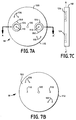
- Figure 7A illustrates an inside surface 120 of an end plate 112
- Figure 7B illustrates an outside surface 122
- Figure 7C is a cross-sectional view along line A-A' with slots 124 drawn in shadow
- Figure 7D is a view of the outside surface 122 of Figure 7B, including additional hardware for driving various system components.
- the storage devices 28 and 30 are mounted onto the end plates 112, via axles 110 and with bearings 92 engaged into slots 124.
- Each slot 124 includes an indent 150 (Fig. 7A) which accepts the bearings 92 when initialising the positions of the storage devices 28 and 30 prior to transferring media thereto.
- Figure 7A illustrates an inside surface 120 of an end plate 112 including: a rotating axle 130 around which the whole transfer buffer 18 rotates; axles 110 around which the storage devices 28 and 30 rotate; axles 126 of the drive rollers 34 (Fig. 2) of the storage device 28; axles 132 of the drive rollers 36 of the storage device 30; and slots 124 which engage the wheel bearings 92 (Fig. 5B) of the storage devices 28 and 30.
- Figure 7C clearly shows that the slots 124 are engageable with the bearings 92 from the inside surfaces 120 of the end plates 112.
- the buffer is rotatable about an axis 130 as shown in Figure 7A.
- the buffer 18 is not limited to being rotatable.
- the transfer of storage devices and the media stored within could occur by moving the storage devices within the buffer first along a linear path, and then turning the storage device 180 degrees to return along an adjacent linear path.
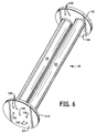
- FIG 6 is a perspective view of a partially constructed transfer buffer 18 which includes two storage devices 28 and 30.
- a motor (not shown) is connected, external to the transfer buffer 18, to a pulley 140 (Fig. 7D) which rotates about an axis 128.
- a belt 142 connects pulley 140 to pulley 138 which, in turn, is connected to and drives one axle 126 of the rollers 34 (Fig. 2).
- the two rollers 34 form a tight nip therebetween so that when one roller 34 is driven, the other roller 34 follows.
- rollers 36 are driven via a system containing a motor (not shown), a pulley 144 (Fig. 7D) rotating about an axle 132 and a pulley 146 rotating about an axis 134.
- the storage devices 28 and 30 are driven via an external motor (not shown) which engages the gears 136 to rotate the axles 110.
- the motors and associated hardware can be mounted external to, or within the transfer buffer 18, as desired.
- the dimensions of the storage devices 28 and 30 are variable to accommodate different size media sheets.
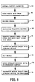
- the operation of the imagesetting system 1 including the transfer buffer 18 is detailed by the flow chart of Figure 8.
- the operating sequence is controlled by the controller 3 (Fig. 1) which, in turn is dependent upon software executed therein.
- media 8 is provided to the imagesetter 10, for example by a supply cassette 11 also referred to as a web supply roll.
- Media may alternatively be supplied by a number of pre-cut sheets, for example stored in a stack.
- the supply rollers 6 move the media 8 onto the recording support surface 9 of the drum 14.
- the imagesetter 10 records a predetermined image onto the media 8 while it is located over the recording support surface 9.
- the transfer buffer 18 is initialised at step 66.
- the steps of initialisation include (I) aligning the nip between the rollers 34 with the opening 23 of the platens 21, (ii) aligning the nip between the rollers 36 with the opening 37 of the platens 25, and (iii) indexing each of the bearings 92 (Fig. 5B) into indents 150 (Fig. 7A) of slots 124 of the end plates 112 (see Figures 5B and 7A).
- the leaf springs 90 are each in an open or extended position so that the retaining rod 102 (Fig.
- the imaged medium 8 is removed from the drum via output rollers 15 (Fig. 1) and new media is brought into the drum from the supply cassette 11 via input rollers 6 at step 68.
- the image sensor 17 detects the traversal of the leading edge of the media and initiates power to the drive rollers 34 at the same transfer speed as the rollers 6 and 15.
- the transfer speed of the various drive rollers indicates to the controller 3 the exact position of the leading edge of the imaged medium 8.
- the imaged medium 8 is driven through rollers 34 until it is positioned between the surface 104 (Fig. 5B) and the bearing 92 as shown in Figure 5B.
- the body or roller 100 of the storage device 28 is activated to rotate about its axis 110 at the same transfer speed as the other rollers, causing the rods 102 to move out of the indents 150 and to clamp down on the medium 8 as shown in Figure 5C.
- the imaged medium 8 is thereafter wrapped onto the external surface of the roller 100 as shown in Figure 5C.
- the spring 90 is contracted so that the bearing 92 is removed from its initial position in the indent 150 ( Figure 7A). The bearing 92 thus pinches the medium 8 onto the surface 104, holding the medium 8 in place as it wraps around the roller 100 as illustrated in Figure 7C.
- the cutters 16 cut the medium sheet and the rollers 6 and 15 stop (step 72).
- the drive rollers 34 and the roller 100 in the storage device 28 continue to operate until the trailing edge of the cut medium is in the vicinity of the opening 23. At this point, the drive rollers 34 and 100 stop and the first cut sheet of media is fully stored in the storage device 28. A next image is transferred onto the media in the drum as previously described. Meanwhile, at step 74 the transfer buffer 18 moves the storage devices therein.
- the buffer is moved so that the nip between the rollers 34 is now aligned with the opening 37 of the platens 25 and the nip between the rollers 36 is aligned with the opening 23 of the platens 21.
- the cut medium 8 which is stored on the storage device 28 is ready for transfer into the processor 12, while an empty storage device 30 is available to receive the next sheet of imaged medium 8 from the drum 14.
- the drive rollers 34 and 100 are activated and the medium 8 stored in the storage device 28 is transferred through the platen 25 into the processor 12.
- the sensor 22 When the sensor 22 detects the leading edge of the medium 8, it transmits an electronic signal to the controller 3 which, in turn, activates the processor input rollers 20 at the same transfer rate as the rollers 34 and 100. When the trailing edge of the medium 8 being transferred into the processor 12 is detected by the sensor 22, the rollers 34 and 100 are deactivated.
- the first and second preferred embodiments of the present invention include a generally cylindrical shaped transfer buffer 18, the particular shape of the buffer 18 is not critical to the principles of the invention.
- the transfer buffer 18 is not limited to a cylindrical shape.
- the movement of the storage devices 28 and 30 from one point to another within the buffer 18 can be implemented by any known transfer means, such as via a belt driven or chain driven transfer system.
- the particular cylindrical shape of the embodiments of the transfer buffer 18 illustrated in the drawings allows an easy manner to transfer the storage devices from one point to another within the buffer 18.
- the buffer 18 could cause the devices to move in a linear path or along a combination of linear and angular paths. Any path for transferring the media (via multiple storage devices) from one component to another within the imagesetting system 1 is a viable alternative for implementing the inventive concepts.
- the transfer buffer could be used with any internal or external drum imagesetting system.
- the transfer buffer could be more broadly used to transfer and buffer any imaged media between any two stages or components within a system.
- the transfer buffer could be used to transfer media between the drum and the mechanical finishing unit (which would be necessary in place of the chemical processor described heretofore).
Landscapes
- Physics & Mathematics (AREA)
- General Physics & Mathematics (AREA)
- Photographic Developing Apparatuses (AREA)
- Feeding Of Articles By Means Other Than Belts Or Rollers (AREA)
Applications Claiming Priority (2)
| Application Number | Priority Date | Filing Date | Title |
|---|---|---|---|
| US09/240,985 US6240260B1 (en) | 1999-01-29 | 1999-01-29 | Method and apparatus for buffer transfer of media sheets between components in an imagesetting system |
| US240985 | 1999-01-29 |
Publications (1)
| Publication Number | Publication Date |
|---|---|
| EP1024404A1 true EP1024404A1 (fr) | 2000-08-02 |
Family
ID=22908742
Family Applications (1)
| Application Number | Title | Priority Date | Filing Date |
|---|---|---|---|
| EP00200302A Withdrawn EP1024404A1 (fr) | 1999-01-29 | 2000-01-31 | Méthode et dispositif de transfert tampon de feuilles entre des components dans un système d'enregistrements d'images |
Country Status (3)
| Country | Link |
|---|---|
| US (1) | US6240260B1 (fr) |
| EP (1) | EP1024404A1 (fr) |
| JP (1) | JP2000219358A (fr) |
Families Citing this family (7)
| Publication number | Priority date | Publication date | Assignee | Title |
|---|---|---|---|---|
| US20030205639A1 (en) * | 2002-05-02 | 2003-11-06 | Agfa Corporation | Method and apparatus for buffer transfer of media sheets between components in an imaging system |
| US6771301B1 (en) * | 2003-03-10 | 2004-08-03 | A.B. Dick Company | Image setting apparatus having drum simulating supports |
| JP4618114B2 (ja) * | 2005-11-25 | 2011-01-26 | ノーリツ鋼機株式会社 | 画像形成装置 |
| US8113507B2 (en) * | 2008-08-29 | 2012-02-14 | Brother Kogyo Kabushiki Kaisha | Image forming apparatus with variable-position guideway of a pair of position guide rollers |
| CN106660724B (zh) | 2014-05-28 | 2019-05-31 | 惠普发展公司,有限责任合伙企业 | 打印介质缓冲 |
| JP7409118B2 (ja) * | 2020-01-31 | 2024-01-09 | 株式会社リコー | 画像形成装置、媒体引渡制御方法及び媒体引渡制御装置 |
| JP7547904B2 (ja) * | 2020-04-01 | 2024-09-10 | 株式会社リコー | シート保持装置、画像形成装置、及び画像形成システム |
Citations (3)
| Publication number | Priority date | Publication date | Assignee | Title |
|---|---|---|---|---|
| GB2128593A (en) * | 1982-10-19 | 1984-05-02 | Hadland John | Web transfer between stations |
| US4511098A (en) * | 1982-11-08 | 1985-04-16 | Fuji Photo Film Co., Ltd. | Film storage device |
| US4593867A (en) * | 1981-12-22 | 1986-06-10 | Fuji Photo Film Co., Ltd. | Film storage device in camera processor |
Family Cites Families (8)
| Publication number | Priority date | Publication date | Assignee | Title |
|---|---|---|---|---|
| JP2696034B2 (ja) | 1992-03-30 | 1998-01-14 | 大日本スクリーン製造株式会社 | シート材の搬送装置 |
| US5345870A (en) * | 1993-02-10 | 1994-09-13 | Miles Inc. | "Direct-to-press" positive lithographic printing plate and method for making same |
| EP0692739B1 (fr) | 1994-07-14 | 2002-12-04 | Agfa Corporation | Procédé et dispositif pour pont de transport de moyens monté de façon pivotante avec un système de contrepoids amelioré |
| US5465955A (en) * | 1994-08-08 | 1995-11-14 | Bayer Corporation | Method and apparatus for an external media buffer |
| JPH08146616A (ja) | 1994-11-18 | 1996-06-07 | Konica Corp | ドラム型転写装置 |
| US5771057A (en) * | 1995-06-29 | 1998-06-23 | Agfa Division, Bayer Corporation | Material supply carousel for thermal imaging apparatus |
| JP3372409B2 (ja) * | 1995-09-26 | 2003-02-04 | シャープ株式会社 | シート排出処理装置 |
| US5949466A (en) * | 1998-05-01 | 1999-09-07 | Eastman Kodak Company | Exposing imagesetter recording film to a dye collection sheet on a transfer apparatus |
-
1999
- 1999-01-29 US US09/240,985 patent/US6240260B1/en not_active Expired - Fee Related
-
2000
- 2000-01-20 JP JP2000011537A patent/JP2000219358A/ja active Pending
- 2000-01-31 EP EP00200302A patent/EP1024404A1/fr not_active Withdrawn
Patent Citations (3)
| Publication number | Priority date | Publication date | Assignee | Title |
|---|---|---|---|---|
| US4593867A (en) * | 1981-12-22 | 1986-06-10 | Fuji Photo Film Co., Ltd. | Film storage device in camera processor |
| GB2128593A (en) * | 1982-10-19 | 1984-05-02 | Hadland John | Web transfer between stations |
| US4511098A (en) * | 1982-11-08 | 1985-04-16 | Fuji Photo Film Co., Ltd. | Film storage device |
Also Published As
| Publication number | Publication date |
|---|---|
| JP2000219358A (ja) | 2000-08-08 |
| US6240260B1 (en) | 2001-05-29 |
Similar Documents
| Publication | Publication Date | Title |
|---|---|---|
| US5769301A (en) | Method and apparatus for pivotally mounted media transport bridge with improved counterbalance system | |
| US6240260B1 (en) | Method and apparatus for buffer transfer of media sheets between components in an imagesetting system | |
| EP0898411B1 (fr) | Procédé et appareil d'enregistrement automatique de plaques d'impression dans un système d'imagerie | |
| EP0825142B1 (fr) | Procédé et appareil pour accumuler temporairement des médias | |
| US6085657A (en) | Redirecting printing media in a prepress printing environment | |
| JPH07281310A (ja) | 写真焼付処理方法及び装置 | |
| US20030205639A1 (en) | Method and apparatus for buffer transfer of media sheets between components in an imaging system | |
| US6772691B2 (en) | System and method for registering media in an imaging system | |
| EP0663615B1 (fr) | Système tampon à deux médias pourvu d'une unité d'embrayage à roue libre | |
| EP0750999B1 (fr) | Appareil de production thermique d'images et méthode de distribution et d'application de matériau | |
| US4833487A (en) | Method of and apparatus for recording image onto a recording medium without subjecting the medium to undesired external forces | |
| JP3529211B2 (ja) | 画像位置情報の形成方法 | |
| JPS63176232A (ja) | シ−ト給送装置 | |
| EP0750997A2 (fr) | Carrousel d'alimentation en matériaux pour appareil de production thermique d'images | |
| WO2001008404A1 (fr) | Appareil de formation d'image | |
| JPH11102092A (ja) | 画像形成装置 | |
| JP2007050997A (ja) | 平版刷版の自動供給装置 | |
| JPH09230571A (ja) | 感光材料の搬送装置 | |
| JP2007031139A (ja) | 平版刷版の自動給排装置 | |
| JP2000089392A (ja) | 感光材料露光装置 | |
| JP2002006470A (ja) | 写真処理装置 | |
| JP2002268232A (ja) | 印刷版自動露光装置 | |
| JP2002258415A (ja) | ループガイド板駆動機構 | |
| JP2002014428A (ja) | 画像記録装置 | |
| JP2002131845A (ja) | 画像記録装置 |
Legal Events
| Date | Code | Title | Description |
|---|---|---|---|
| PUAI | Public reference made under article 153(3) epc to a published international application that has entered the european phase |
Free format text: ORIGINAL CODE: 0009012 |
|
| AK | Designated contracting states |
Kind code of ref document: A1 Designated state(s): DE FR GB |
|
| AX | Request for extension of the european patent |
Free format text: AL;LT;LV;MK;RO;SI |
|
| 17P | Request for examination filed |
Effective date: 20010202 |
|
| AKX | Designation fees paid |
Free format text: DE FR GB |
|
| STAA | Information on the status of an ep patent application or granted ep patent |
Free format text: STATUS: THE APPLICATION HAS BEEN WITHDRAWN |
|
| 18W | Application withdrawn |
Effective date: 20040424 |