EP1024551A2 - Schaltung zur Verbesserung der Isolierung für eine doppelpolarisierte Antenne - Google Patents
Schaltung zur Verbesserung der Isolierung für eine doppelpolarisierte Antenne Download PDFInfo
- Publication number
- EP1024551A2 EP1024551A2 EP99402999A EP99402999A EP1024551A2 EP 1024551 A2 EP1024551 A2 EP 1024551A2 EP 99402999 A EP99402999 A EP 99402999A EP 99402999 A EP99402999 A EP 99402999A EP 1024551 A2 EP1024551 A2 EP 1024551A2
- Authority
- EP
- European Patent Office
- Prior art keywords
- signal
- canceling
- port
- conductor
- length
- Prior art date
- Legal status (The legal status is an assumption and is not a legal conclusion. Google has not performed a legal analysis and makes no representation as to the accuracy of the status listed.)
- Withdrawn
Links
Images
Classifications
-
- H—ELECTRICITY
- H01—ELECTRIC ELEMENTS
- H01Q—ANTENNAS, i.e. RADIO AERIALS
- H01Q21/00—Antenna arrays or systems
- H01Q21/24—Combinations of antenna units polarised in different directions for transmitting or receiving circularly and elliptically polarised waves or waves linearly polarised in any direction
-
- H—ELECTRICITY
- H01—ELECTRIC ELEMENTS
- H01Q—ANTENNAS, i.e. RADIO AERIALS
- H01Q1/00—Details of, or arrangements associated with, antennas
- H01Q1/52—Means for reducing coupling between antennas; Means for reducing coupling between an antenna and another structure
- H01Q1/521—Means for reducing coupling between antennas; Means for reducing coupling between an antenna and another structure reducing the coupling between adjacent antennas
- H01Q1/525—Means for reducing coupling between antennas; Means for reducing coupling between an antenna and another structure reducing the coupling between adjacent antennas between emitting and receiving antennas
-
- H—ELECTRICITY
- H04—ELECTRIC COMMUNICATION TECHNIQUE
- H04B—TRANSMISSION
- H04B1/00—Details of transmission systems, not covered by a single one of groups H04B3/00 - H04B13/00; Details of transmission systems not characterised by the medium used for transmission
- H04B1/38—Transceivers, i.e. devices in which transmitter and receiver form a structural unit and in which at least one part is used for functions of transmitting and receiving
- H04B1/40—Circuits
- H04B1/50—Circuits using different frequencies for the two directions of communication
- H04B1/52—Hybrid arrangements, i.e. arrangements for transition from single-path two-direction transmission to single-direction transmission on each of two paths or vice versa
- H04B1/525—Hybrid arrangements, i.e. arrangements for transition from single-path two-direction transmission to single-direction transmission on each of two paths or vice versa with means for reducing leakage of transmitter signal into the receiver
Definitions
- the present invention pertains to transmitting and receiving antennas, and in particular, to isolating from each other antennas in an antenna system.
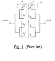
- an ordinary dual-polarized antenna system consisting of at least two mutually orthogonal elements 12 , a transmitter antenna element 16 for transmitting a transmitter signal, and a receiver antenna element 17 for receiving, simultaneously, a receiver signal.
- the antenna system shown includes two arrays 10 and 11 , each consisting of four parallel antenna elements, each array referred to as an antenna.
- the transmitter signal is provided through port #1 to the transmitter antenna elements 10
- the receiver signal is provided at port #2 after being picked up by the receiver antenna elements 11 .
- the receiver antenna array 11 picks up some of the signal from the transmitter antenna array 10 .
- the prior art often uses parasitic elements or walls of conducting material to provide isolation. This requires trial and error and is thus time-consuming and expensive. Further, the parasitic walls degrade antenna performance. Also, a particular configuration of parasitic elements or walls works for only one frequency band; a different arrangement must be used, in general, for any other frequency band, and will work for only one particular array geometry.
- the isolation means comprises an amplifier section coupled to the transmitting antenna and to the first receiving antenna, for amplifying and modulating the signal received by the first receiving antenna and then providing it to the transmitting antenna; a phase-shifter coupled to the second receiving antenna; and a power combiner having inputs coupled to the first receiving antenna and to the phase shifter, and having an output coupled to the amplifier section.
- the power combiner combines the signal picked up by the first receiving antenna with the signal received by the second receiving antenna and then phase-shifted by the phase shifter.
- This phase-shifted signal is a 180 degree phase-shifted copy of the same signal from the phase shifter. (Thus, in this, the undesired signal from the transmitting element appears at the output port of the first receiving element, and cancellation occurs later, in the combiner.)
- each transmitting array The two parts of each transmitting array are driven in phase quadrature (relative to each other) and at equal power, and the two antenna arrays are spaced sufficiently close to each other so that radiation emitted by one array and received by the other array undergoes a canceling effect before reaching the radio frequency generator associated with the other array.
- the present invention achieves the above object in an isolation circuit, for use in a dual polarized antenna system having a first port responsive to a transmission signal and attached to a transmitter antenna, for providing a transmitter signal, and also having a second port attached to a receiver antenna, the isolation circuit comprising: a coupling means for deriving a canceling signal from the transmission signal by coupling to the transmission signal at the first port, and for providing the canceling signal at the second port, the coupling means providing the canceling signal with an amplitude substantially equal to that of the transmitter signal arriving at the second port via the receiver antenna; and a conductor of a canceling length, for conducting the canceling signal from the first port to the second port, and for phase-shifting the canceling signal; wherein the canceling length is adjusted so that the canceling signal as provided at the second port is substantially 180° out of phase compared to the transmitter signal arriving at the second port via the receiver antenna.
- the coupling means includes a first discrete coupler for coupling a portion of the transmission signal at the first port into the conductor of a canceling length, and a second discrete coupler for coupling the phase-shifted canceling signal out of the conductor of a canceling length into the receiver feedline at the second port, and further wherein each coupler includes a coupling length of the conductor of a canceling length and a coupling length of either the transmitter or receiver feedline, and holds the coupling length of the conductor in a fixed spatial relation to the coupling length of the feedline.
- the coupling means includes a first, discrete coupler for coupling the transmission signal at the first port into the conductor of a canceling length, and a probe antenna for providing the phase-shifted canceling signal to the second port via the receiver antenna, wherein the first coupler includes a coupling length of the conductor of a canceling length and a coupling length of the transmitter feedline, and holds the coupling length of the conductor in a fixed spatial relation to the coupling length of feedline.
- the coupling means includes a first coupler for coupling a portion of the transmission signal at the first port into the conductor of a canceling length, and a second coupler for coupling the phase-shifted canceling signal out of the conductor of a canceling length into the receiver feedline at the second port.
- the coupling means includes a first coupler for coupling the transmission signal at the first port into the conductor of a canceling length, and a probe antenna for providing the phase-shifted canceling signal to the second port via the receiver antenna.
- the present invention in the preferred embodiment (shown in the main figure below) would likely perform more consistently and would be implemented with less trial and error because it uses direct coupling, compared to using a secondary antenna aligned to provide the correct gain and phase.
- the present invention is simpler (no driving the transmitting elements, identified as consisting of two groups of elements, in phase quadrature), and the present invention can be used without constraining how the transmitter and receiver antennas are spaced.
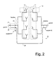
- an isolation improvement circuit for a dual-polarized antenna consisting of parallel transmitter antenna elements 10 oriented orthogonally, in either a physical or electrical sense, to parallel receiver antenna elements 11 , is shown in the preferred embodiment, as consisting of a coupler #1, responsive to a transmission signal provided to port #1, for providing to a coupler #2, through a conductor 24 of canceling length, a time-delayed transmission signal S 21,D .
- the canceling length of the conductor 24 is fixed so that the time-delayed transmission signal S 21,D reaches port #2 out of phase compared to the portion S 21 of the transmitter signal arriving at port #2 through the receiver antenna by an amount equal to approximately one half of a wavelength of the carrier wave, i.e. so that S 21 and S 21,D differ in phase by approximately 180 degrees.
- Fig. 2 and also Fig. 1 and 3, of the antenna elements 16 and 17 are intended only to illustrate that in the dual-polarized antenna the transmitter and receiver antenna elements are mutually orthogonal. Although the depictions suggest that the transmitter and receiver elements are physically orthogonal, the required orthogonality can also be provided electrically, using phased arrays, one for transmitting and one for receiving.
- the two couplers #1 and #2 are selected to provide, in combination, the time-delayed transmission signal S 21,D at approximately the same amplitude as that of S 21 .
- port #2 receives a portion S 21 of both the undesired transmitter signal as well as a canceling signal, the time-delayed transmission signal S 21,D , approximately equal in magnitude to S 21 but 180 degrees out of phase.
- the canceling signal S 21,D therefore substantially cancels the undesired signal S 21 .
- both the phase and amplitude of S 21 are measured before sizing the isolation circuit, i.e. before determining the canceling length of conductor 24, and before determining the coupling of couplers #1 and #2, in combination, needed to provide the proper canceling amplitude.
- Coupling is provided by placing a portion of the conductor 24 parallel to the feedline leading from port #1 or to port #2.
- Dashed rectangle 26 encloses the part of the conductor and part of the feedline where coupling occurs; the dashed rectangle is encloses what is called here the coupling length of the conductor at port #1 and the coupling length of the feedline at port #1.
- the coupling length of the conductor at port #1 is arranged to be parallel to the coupling length of the feedline at port #1 and is held in fixed spatial relation to the feedline at port #1 by various means, depending on the particular application.
- the coupling length of the conductor at port #1 is arranged parallel to the feedline at a standoff designed to provide the required gain, typically several or tens of thousandths of an inch.
- the coupling length of the conductor in this case would itself also be etched into the printed circuit board, thereby being held in fixed spatial relation to the coupling length of the feedline at port #1.
- in-line couplers In some applications, it is preferable to use in-line couplers. Referring again to Fig. 2, such a coupler would include both the coupling length of the conductor at port #1 (the part within the dashed rectangle 18 ) as well as the coupling length of the feedline at port #1 (the part of the feedline within the same dashed rectangle 18 ).
- the dashed rectangle of Fig. 2 would, in the case of an in-line coupler, represent housing that encloses the conductor and feedline coupling lengths, and would structurally support the two coupling lengths in a fixed spatial relation. Both ends 21 and 22 of the feedline coupling length would then be soldered to the feedline, and the downstream end 25 of the conductor coupling length would be soldered to the rest of the conductor 24.
- the coupler is a more narrowband coupler, i.e. particularly responsive only to the frequency of the carrier wave of the transmitter signal.
- the coupler units are, from the standpoint of the user, essentially the same.
- the in-line couplers are typically enclosed modules, usually rectangular in cross section, and as noted above support the coupling length of the feedline and coupling length of the conductor, within a housing, in a fixed spatial relation. If the antenna system is for microwave communication, inside the coupler there will be any one of various known coupling structures for coupling microwaves from one waveguide to another, the conductor of a canceling length being in this case a waveguide of one known sort or another (such as, for example, a transverse electric rectangular waveguide).
- the antenna system is for radiofrequency communication
- the conductor of a canceling length being in this case one suitable for radiofrequency communication, such as coaxial cable.
- the coupling length of the conductor within the coupler itself i.e. within the region where coupling occurs, as indicated for coupler #1 by the dashed rectangle 26 , is not necessarily the same form of conductor as the conductor of a canceling length outside of the coupler, and similarly for the coupling length of the feedline and feedline outside of the coupler.
- the coupling length of conductor 24 may be a conducting metal etched onto a printed circuit board, but outside the coupler the conductor 24 may be coaxial cable.
- the present invention is not intended to be restricted to using any particular kind of conductors for providing a time delay in the transmission signal.
- Any means of conducting the transmission signal so as to provide an adjustable time delay is intended to be within the scope of the present invention.
- the conductor 24 can be coaxial cable, parallel wire, wire over ground, strip, or shielded strip transmission line, or any of various configurations of wave guides.
- the conductor 24 can include various capacitive or inductive elements that contribute to creating a time delay in the transmission signal provided to port #2.
- in sizing the conductor 24 it is advantageous to adjust such capacitive and inductive elements, as well as the length of the conductor. In other embodiments, sizing the conductor 24 is accomplished purely by adjusting such capacitive and inductive elements.
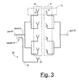
- the canceling signal extracted at port #1 by coupler #1 is provided to port #2 by transmitting it from a probe antenna 32 to the receiving antenna 11 that feed port #2, the probe antenna and receiving antenna 11 making up a second, non-discrete coupler.
- a conductor of some canceling length is used to provide an appropriate phase delay so that when the signal provided by the probe antenna 32 arrives at port #2, it is substantially 180 degrees out of phase with S 21 .
- the gain of coupler #1 must be pre-set so that when the signal S 21,D provided through the probe antenna 32 arrives at port #2, it is substantially equal in magnitude to S 21 , the portion of the transmitter signal arriving at port #2.
Landscapes
- Engineering & Computer Science (AREA)
- Computer Networks & Wireless Communication (AREA)
- Signal Processing (AREA)
- Variable-Direction Aerials And Aerial Arrays (AREA)
- Transceivers (AREA)
Applications Claiming Priority (2)
| Application Number | Priority Date | Filing Date | Title |
|---|---|---|---|
| US09/238,837 US6141539A (en) | 1999-01-27 | 1999-01-27 | Isolation improvement circuit for a dual-polarization antenna |
| US238837 | 1999-01-27 |
Publications (2)
| Publication Number | Publication Date |
|---|---|
| EP1024551A2 true EP1024551A2 (de) | 2000-08-02 |
| EP1024551A3 EP1024551A3 (de) | 2001-09-26 |
Family
ID=22899532
Family Applications (1)
| Application Number | Title | Priority Date | Filing Date |
|---|---|---|---|
| EP99402999A Withdrawn EP1024551A3 (de) | 1999-01-27 | 1999-11-30 | Schaltung zur Verbesserung der Isolierung für eine doppelpolarisierte Antenne |
Country Status (5)
| Country | Link |
|---|---|
| US (1) | US6141539A (de) |
| EP (1) | EP1024551A3 (de) |
| CN (2) | CN1169258C (de) |
| AU (1) | AU763788B2 (de) |
| BR (1) | BR9902722A (de) |
Cited By (5)
| Publication number | Priority date | Publication date | Assignee | Title |
|---|---|---|---|---|
| GB2372902A (en) * | 2000-12-20 | 2002-09-04 | Univ Heriot Watt | Integrated cancellation antenna for full-duplex microwave transceivers |
| KR100598736B1 (ko) * | 2003-04-30 | 2006-07-10 | 주식회사 엘지텔레콤 | 소형 트리폴 안테나 |
| US7508345B2 (en) | 2003-06-24 | 2009-03-24 | Qisda Corporation | PIFA antenna arrangement for a plurality of mobile radio frequency bands |
| US20110116404A1 (en) * | 2009-11-18 | 2011-05-19 | Fujitsu Limited | Radio communication device and method of controlling radio communication device |
| EP2838207A4 (de) * | 2012-04-09 | 2015-02-18 | Huawei Tech Co Ltd | Drahtlose vollduplex-kommunikationsvorrichtung, verfahren und system |
Families Citing this family (28)
| Publication number | Priority date | Publication date | Assignee | Title |
|---|---|---|---|---|
| SE520836C3 (sv) * | 1998-11-18 | 2003-10-01 | Saab Ab | Repeterstörsändare samt hylsarrangemang för densamma |
| ES2160087B1 (es) * | 2000-02-18 | 2003-03-01 | Mier Comunicaciones S A | Procedimiento para la repeticion de señales en insofrecuencia y repetidor de señales en isofrecuencia. |
| US20080129594A1 (en) * | 2006-11-30 | 2008-06-05 | Pera Robert J | Dual-polarization antenna feeds for mimo applications |
| US7688275B2 (en) * | 2007-04-20 | 2010-03-30 | Skycross, Inc. | Multimode antenna structure |
| US8866691B2 (en) | 2007-04-20 | 2014-10-21 | Skycross, Inc. | Multimode antenna structure |
| US8344956B2 (en) | 2007-04-20 | 2013-01-01 | Skycross, Inc. | Methods for reducing near-field radiation and specific absorption rate (SAR) values in communications devices |
| US7688273B2 (en) | 2007-04-20 | 2010-03-30 | Skycross, Inc. | Multimode antenna structure |
| US8023886B2 (en) * | 2007-09-28 | 2011-09-20 | Broadcom Corporation | Method and system for repeater with gain control and isolation via polarization |
| US8244175B2 (en) * | 2007-09-28 | 2012-08-14 | Broadcom Corporation | Method and system for signal repeater with gain control and spatial isolation |
| CN101677149B (zh) * | 2008-09-19 | 2013-04-24 | 华为技术有限公司 | 一种提高天线隔离度的方法、系统及装置 |
| US8866692B2 (en) * | 2008-12-19 | 2014-10-21 | Apple Inc. | Electronic device with isolated antennas |
| CN102253369B (zh) * | 2011-05-31 | 2012-12-26 | 西安空间无线电技术研究所 | 一种天线交叉极化互耦消除方法 |
| US10096910B2 (en) * | 2012-06-13 | 2018-10-09 | Skycross Co., Ltd. | Multimode antenna structures and methods thereof |
| KR102116278B1 (ko) * | 2012-08-14 | 2020-05-29 | 주식회사 케이엠더블유 | 분리도 제공 장치를 구비한 이중편파 안테나 |
| DE112013005067T5 (de) * | 2012-10-18 | 2015-06-25 | Mitsubishi Electric Corp. | Entkopplungsschaltkreis |
| JP6095444B2 (ja) * | 2013-03-29 | 2017-03-15 | 富士通テン株式会社 | アンテナ装置およびレーダ装置 |
| CN104144038B (zh) * | 2013-05-10 | 2018-01-26 | 普天信息技术研究院有限公司 | 一种lte系统下行控制信道的信号发射方法与装置 |
| US20150116162A1 (en) | 2013-10-28 | 2015-04-30 | Skycross, Inc. | Antenna structures and methods thereof for determining a frequency offset based on a differential magnitude |
| RU2695102C2 (ru) * | 2014-03-26 | 2019-07-19 | Хуавей Текнолоджиз Ко., Лтд. | Базовая станция |
| WO2015149373A1 (zh) | 2014-04-04 | 2015-10-08 | 华为技术有限公司 | 同频干扰抵消方法、装置及系统 |
| CN104283007A (zh) * | 2014-09-26 | 2015-01-14 | 电子科技大学 | 一种用于降低天线阵列单元间互耦的馈电网络 |
| US9979069B2 (en) | 2016-05-02 | 2018-05-22 | Motorola Solutions, Inc. | Wireless broadband/land mobile radio antenna system |
| CN106953173B (zh) * | 2017-02-23 | 2020-04-28 | 上海华为技术有限公司 | 一种双极化天线隔离装置及方法 |
| CN108226872A (zh) * | 2018-01-29 | 2018-06-29 | 深圳市粤嘉鸿电子有限公司 | 一种微波多普勒雷达系统 |
| KR102070405B1 (ko) * | 2018-10-26 | 2020-01-29 | 주식회사 케이엠더블유 | 분리도 제공 장치를 구비한 이중편파 안테나 |
| CN110797654B (zh) * | 2019-12-03 | 2025-04-25 | 惠州硕贝德无线科技股份有限公司 | 一种同频带间高隔离度天线及微基站 |
| CN112532472B (zh) * | 2020-11-09 | 2022-11-04 | 广东电网有限责任公司广州供电局 | 一种相量测量单元上传延时的测试方法 |
| CN117832885A (zh) * | 2024-01-19 | 2024-04-05 | 联想(北京)有限公司 | 一种电子设备 |
Family Cites Families (14)
| Publication number | Priority date | Publication date | Assignee | Title |
|---|---|---|---|---|
| US2103357A (en) * | 1935-08-19 | 1937-12-28 | Telefunken Gmbh | Ultrashort wave system |
| US3699444A (en) * | 1969-02-17 | 1972-10-17 | American Nucleonics Corp | Interference cancellation system |
| US4480255A (en) * | 1982-12-06 | 1984-10-30 | Motorola Inc. | Method for achieving high isolation between antenna arrays |
| JPS60173934A (ja) * | 1984-02-17 | 1985-09-07 | Mitsubishi Electric Corp | 電波送受信装置 |
| US4728960A (en) * | 1986-06-10 | 1988-03-01 | The United States Of America As Represented By The Secretary Of The Air Force | Multifunctional microstrip antennas |
| US5373297A (en) * | 1990-12-31 | 1994-12-13 | The United States Of America As Represented By The Secretary Of The Navy | Microwave repeater with broadband active and/or passive isolation control |
| US5264862A (en) * | 1991-12-10 | 1993-11-23 | Hazeltine Corp. | High-isolation collocated antenna systems |
| US5444864A (en) * | 1992-12-22 | 1995-08-22 | E-Systems, Inc. | Method and apparatus for cancelling in-band energy leakage from transmitter to receiver |
| CA2127189A1 (en) * | 1993-08-06 | 1995-02-07 | James John Crnkovic | Apparatus and method for attenuating an undesired signal in a radio transceiver |
| US5574978A (en) * | 1994-05-12 | 1996-11-12 | American Nucleonics Corporation | Interference cancellation system and radio system for multiple radios on a small platform |
| US5647379A (en) * | 1994-11-22 | 1997-07-15 | Ventritex, Inc. | Correlator based electromagnetic interference responsive control system useful in medical devices |
| US5486836A (en) * | 1995-02-16 | 1996-01-23 | Motorola, Inc. | Method, dual rectangular patch antenna system and radio for providing isolation and diversity |
| US5691978A (en) * | 1995-04-07 | 1997-11-25 | Signal Science, Inc. | Self-cancelling full-duplex RF communication system |
| US6201511B1 (en) * | 1997-04-18 | 2001-03-13 | Ericsson Inc. | Composite antenna for duplexer-free duplex operation terminals and method |
-
1999
- 1999-01-27 US US09/238,837 patent/US6141539A/en not_active Expired - Lifetime
- 1999-05-20 CN CNB991066855A patent/CN1169258C/zh not_active Expired - Fee Related
- 1999-05-20 CN CNB2004100562202A patent/CN100385735C/zh not_active Expired - Fee Related
- 1999-07-12 BR BR9902722-4A patent/BR9902722A/pt not_active IP Right Cessation
- 1999-11-30 EP EP99402999A patent/EP1024551A3/de not_active Withdrawn
- 1999-12-16 AU AU65314/99A patent/AU763788B2/en not_active Ceased
Cited By (9)
| Publication number | Priority date | Publication date | Assignee | Title |
|---|---|---|---|---|
| GB2372902A (en) * | 2000-12-20 | 2002-09-04 | Univ Heriot Watt | Integrated cancellation antenna for full-duplex microwave transceivers |
| GB2372902B (en) * | 2000-12-20 | 2004-06-16 | Univ Heriot Watt | Integrated cancellation antenna for full-duplex microwave transceivers |
| KR100598736B1 (ko) * | 2003-04-30 | 2006-07-10 | 주식회사 엘지텔레콤 | 소형 트리폴 안테나 |
| US7508345B2 (en) | 2003-06-24 | 2009-03-24 | Qisda Corporation | PIFA antenna arrangement for a plurality of mobile radio frequency bands |
| US20110116404A1 (en) * | 2009-11-18 | 2011-05-19 | Fujitsu Limited | Radio communication device and method of controlling radio communication device |
| EP2326018A1 (de) * | 2009-11-18 | 2011-05-25 | Fujitsu Limited | Funkkommunikationsvorrichtung mit reduzierter Antennenkorrelation und Verfahren zur Steuerung der Funkkommunikationsvorrichtung |
| US8670338B2 (en) | 2009-11-18 | 2014-03-11 | Fujitsu Limited | Radio communication device and method of controlling radio communication device |
| EP2838207A4 (de) * | 2012-04-09 | 2015-02-18 | Huawei Tech Co Ltd | Drahtlose vollduplex-kommunikationsvorrichtung, verfahren und system |
| US9520908B2 (en) | 2012-04-09 | 2016-12-13 | Huawei Technologies Co., Ltd. | Full-duplex radio communication device, method and system |
Also Published As
| Publication number | Publication date |
|---|---|
| BR9902722A (pt) | 2001-01-09 |
| AU6531499A (en) | 2000-08-03 |
| CN1169258C (zh) | 2004-09-29 |
| AU763788B2 (en) | 2003-07-31 |
| CN100385735C (zh) | 2008-04-30 |
| EP1024551A3 (de) | 2001-09-26 |
| US6141539A (en) | 2000-10-31 |
| CN1567652A (zh) | 2005-01-19 |
| CN1264188A (zh) | 2000-08-23 |
Similar Documents
| Publication | Publication Date | Title |
|---|---|---|
| US6141539A (en) | Isolation improvement circuit for a dual-polarization antenna | |
| EP0516440B1 (de) | Mikrostreifenantenne | |
| CN112234344B (zh) | 天线装置及电子设备 | |
| US7209080B2 (en) | Multiple-port patch antenna | |
| US6509883B1 (en) | Signal coupling methods and arrangements | |
| US6233434B1 (en) | System for transmitting/receiving a signal having a carrier frequency band for a radio base station | |
| KR100957852B1 (ko) | 고격리 무선 중계기용 광대역 스택 패치 배열 안테나 | |
| CN112117533A (zh) | 双频双线极化相控阵天线及天线单元 | |
| US20090028074A1 (en) | Antenna feed network for full duplex communication | |
| US6064348A (en) | Method and apparatus for a dual frequency band antenna | |
| JPH04223705A (ja) | 偏波均一制御を備えたパッチアンテナ | |
| TWI863405B (zh) | 天線陣列與雙饋入圓極化寬頻天線 | |
| CN116073112B (zh) | 天线和基站设备 | |
| WO2015076913A1 (en) | Wideband star antenna with tem horn array | |
| KR100902496B1 (ko) | 편파변환 안테나 및 통신 장치 | |
| US6150983A (en) | Device for receiving and/or transmitting electromagnetic radiation | |
| US20130307747A1 (en) | Vehicular antenna | |
| KR100883954B1 (ko) | 원편파 안테나, 중계기 용 안테나 및 이를 이용하는중계기와 이동 통신 시스템 | |
| KR101001664B1 (ko) | 수직 편파 및 수평 편파의 동시 송수신이 가능한 안테나 | |
| US20050116866A1 (en) | Simple gain testing method | |
| CN115441167A (zh) | 集成有双工器的紧凑型低剖面开孔天线 | |
| KR20020010932A (ko) | 복수의 차량 전자 구성요소용 차량 안테나 시스템 | |
| Knox | Passive interference cancellation in a 2× 2 STAR MIMO antenna network | |
| US20060176218A1 (en) | Gain-adjustable antenna | |
| Kuznetcov et al. | Dual-polarization multi-layer antenna by patch asymmetry with simple integrated feeding for in-band full-duplex systems |
Legal Events
| Date | Code | Title | Description |
|---|---|---|---|
| PUAI | Public reference made under article 153(3) epc to a published international application that has entered the european phase |
Free format text: ORIGINAL CODE: 0009012 |
|
| AK | Designated contracting states |
Kind code of ref document: A2 Designated state(s): AT BE CH CY DE DK ES FI FR GB GR IE IT LI LU MC NL PT SE |
|
| AX | Request for extension of the european patent |
Free format text: AL;LT;LV;MK;RO;SI |
|
| PUAL | Search report despatched |
Free format text: ORIGINAL CODE: 0009013 |
|
| AK | Designated contracting states |
Kind code of ref document: A3 Designated state(s): AT BE CH CY DE DK ES FI FR GB GR IE IT LI LU MC NL PT SE |
|
| AX | Request for extension of the european patent |
Free format text: AL;LT;LV;MK;RO;SI |
|
| RIC1 | Information provided on ipc code assigned before grant |
Free format text: 7H 01Q 1/52 A, 7H 01Q 21/24 B, 7G 01S 7/03 B |
|
| 17P | Request for examination filed |
Effective date: 20020115 |
|
| AKX | Designation fees paid |
Free format text: AT BE CH CY DE DK ES FI FR GB GR IE IT LI LU MC NL PT SE |
|
| 17Q | First examination report despatched |
Effective date: 20020527 |
|
| STAA | Information on the status of an ep patent application or granted ep patent |
Free format text: STATUS: THE APPLICATION HAS BEEN WITHDRAWN |
|
| 18W | Application withdrawn |
Effective date: 20030925 |