EP1024558A2 - Connecting device for high-voltage cable - Google Patents
Connecting device for high-voltage cable Download PDFInfo
- Publication number
- EP1024558A2 EP1024558A2 EP00400219A EP00400219A EP1024558A2 EP 1024558 A2 EP1024558 A2 EP 1024558A2 EP 00400219 A EP00400219 A EP 00400219A EP 00400219 A EP00400219 A EP 00400219A EP 1024558 A2 EP1024558 A2 EP 1024558A2
- Authority
- EP
- European Patent Office
- Prior art keywords
- connector portion
- coiled
- transformer
- connecting device
- cable
- Prior art date
- Legal status (The legal status is an assumption and is not a legal conclusion. Google has not performed a legal analysis and makes no representation as to the accuracy of the status listed.)
- Withdrawn
Links
Images



Classifications
-
- H—ELECTRICITY
- H01—ELECTRIC ELEMENTS
- H01R—ELECTRICALLY-CONDUCTIVE CONNECTIONS; STRUCTURAL ASSOCIATIONS OF A PLURALITY OF MUTUALLY-INSULATED ELECTRICAL CONNECTING ELEMENTS; COUPLING DEVICES; CURRENT COLLECTORS
- H01R13/00—Details of coupling devices of the kinds covered by groups H01R12/70 or H01R24/00 - H01R33/00
- H01R13/46—Bases; Cases
- H01R13/53—Bases or cases for heavy duty; Bases or cases for high voltage with means for preventing corona or arcing
Definitions
- the present invention relates to a connecting device used for connecting a high-voltage cable to a connector portion provided in a transformer.
- the transformer generates a high electrical voltage.
- the high electrical voltage thus produced is applied to electrical apparatuses, such as office or home appliances for different purposes.
- the connecting device according to the invention is used for sending the high electrical voltage to the electrical apparatuses. Further, the invention concerns methods of connecting such a high-voltage cable to a transformer.
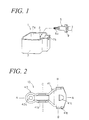
- FIG. 1 shows a known connecting technique, according to which a high-voltage cable used for sending a high electrical voltage is connected to a connector portion 3 of a transformer 1 in such electrical apparatuses.
- the transformer 1 comprises a vertically-extending housing 7.
- the housing 7 contains a primary coil and a secondary coil which generate high electrical voltages as a function of the inputted variable current.
- the housing 7 may also contain various electronic parts such as condensers, diodes or impedance elements, connected to each coil.
- the housing 7 is provided with a hollow portion 7a and a base from which a connector portion 3 of the transformer 1 extends into the hollow portion 7a.
- the end portion of the secondary coil of transformer 1 may thus be connected to an electronic component.
- the latter includes an end section which may form a rod-shaped terminal portion.
- the connector portion 3 of transformer 1 may be comprised of the terminal portion of an impedance element, e.g. a capacitor in the housing 7.
- the connector portion 3 of transformer 1 may also be comprised of a lead wire extending from the electronic component.
- the high-voltage cable 5 usually has a conductive portion 5a consisting of a plurality of copper wires, and a resin coating.
- a conductive portion 5a consisting of a plurality of copper wires, and a resin coating.
- an epoxy resin or the like is filled into the hollow portion 7a, so that the connected portion between the high-voltage cable and the connector portion 3 of the transformer 1 is sealed with the resin.
- a rubber grommet 9 is fitted onto part of the circular peripheral zone of the high-voltage cable 5.
- the hollow portion 7a of housing 7 includes a rectangular side chamber, whose outermost face has a notch 7b vertically atop thereof.
- the transformer 1 When the transformer 1 generates a high electrical voltage, it also generates noise through the high-voltage cable 5, and hence a countermeasure for reducing noise becomes necessary. To this end, either a magnetic core is set around the cylindrical outer surface of the high-voltage cable 5, or an impedance element is inserted in the conductive part of the high-voltage cable 5 so as to curb the noise current flowing in the high-voltage cable 5.
- these methods yield only a limited effect, and there is a need for a more efficient noise-suppressing technique.
- a coiled-type, high-voltage noise-suppressing cable may be used, instead of the high-voltage cable 5.
- the coiled-type, high-voltage noise-suppressing cable comprises at least a core element of magnetic material, a coiled portion at least including a conductive wire for passing a high electrical voltage.
- the coil is helically wound around the core element, and a coating entirely covers the core element and coiled portion. Such a structure is designed to suppress noise efficiently.
- the conductive wires commonly used in a coiled-type cable for preventing high-voltage noise include wires such as nickel-chromium wires.
- wires such as nickel-chromium wires.
- such conductive wires are ill suited for soldering. Accordingly, when using the above technique, the high-voltage cable 5 cannot be soldered directly to the connector portion 3 of the transformer 1.
- An object of the present invention is to provide a connecting device with improved noise-suppressing capacity using a coiled-type cable for preventing high-voltage noise and which can easily connect the coiled-type, high-voltage noise-suppressing cable to a transformer, as well as to provide a method of connecting the coiled-type, high-voltage noise-suppressing cable to the transformer.
- a metallic connecting device for connecting a high-voltage electrical cable to a transformer having a connector portion from which a high electrical voltage is outputted.
- the high-voltage electrical cable includes a coiled-type high-voltage noise-suppressing cable at least comprising:
- the connecting device comprises:
- the transformer is provided with an electronic part including a rod-shaped terminal portion.
- the connector portion of the transformer may be comprised of the rod-shaped terminal portion, while the solder connector portion of the connecting device may be substantially in the form of a cup having a base with a through hole.
- the rod-shaped terminal portion is then passed through the through hole, and is connectable and securable to the solder connector portion by soldering.
- solder connector portion of the connecting device may be comprised of a substantially flat plate which is put into contact with the rod-shaped terminal portion along the length direction thereof. The rod-shaped terminal portion is then connected and fixed to the solder connector portion by soldering.
- solder connector portion of the connecting device may be comprised of a pair of lips extending substantially in parallel, between which the rod-shaped terminal portion is inserted. The rod-shaped terminal portion is then connected and fixed to the solder connector portion by soldering.
- the coiled-type high-voltage noise-suppressing cable typically comprises an end portion which is stripped of its coating so that the coiled portion is exposed.
- the cramping connector portion may comprise a first barrel portion configured to receive the coiled portion of the coiled-type high-voltage noise-suppressing cable in press-fit engagement, and a second barrel portion configured to receive the coiled-type high-voltage noise-suppressing cable in cramped engagement with its coating.
- the second barrel portion comprises a base wall and a detent formed on the base wall.
- the method comprises the steps of:
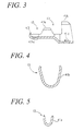
- FIG. 2 is a top plan view of the connecting device according to a first embodiment of the present invention.
- FIG. 3, FIG. 4 and FIG. 5 are respectively a cross-sectional views of the connecting device along lines A-A, B-B and C-C of FIG. 2.
- FIG. 6 is a partially exploded side view of a coiled-type high-voltage noise-suppressing cable. This cable is connected to a transformer through a connecting device according to the invention.
- noise-suppressing electrical cable 11 coiled-type high-voltage noise-suppressing cables 11 (hereinafter referred to as "noise-suppressing electrical cable”) shown in FIG. 6.
- the noise-suppressing electrical cable 11 is connected to a connector portion 3, mounted in a transformer 1 as shown in FIG. 1, via a connecting device 13 shown in FIGS. 2 to 5.
- the configuration of transformer 1 used is the same as the known one.
- the hollow portion 7a of transformer 1 is filled with resin after a noise-suppressing electrical cable 11 has been connected.
- the space formed between the noise-suppressing electrical cable 11 and the notched portion 7b of the housing 7 is sealed by a rubber grommet 9.
- the noise-suppressing electrical cable 11 used in the present embodiments has the following technical features. As shown in FIG. 6, this cable 11 first includes a fibrous reinforcement thread 21a comprised of glass fibers and synthetic fibers. A resin material mixed with ferrite powder (a magnetic material) is then extruded thereon, yielding a core element 21 having a small diameter. Subsequently, a conductive wire 23 for sending a high-electrical voltage is wound around the core element 21, to form a coiled portion 25. Thereafter, the cylindrical outer surface of the coiled portion 25 is covered with a coating 33 comprising a conductive internal layer 27, an insulating layer 29 and an external sheath 31.
- a coating 33 comprising a conductive internal layer 27, an insulating layer 29 and an external sheath 31.
- the connecting device 13 may be integrally formed by a stamping method from a single metal piece.
- One end of the connecting device 13 has a cramping connector portion 41 into which a noise-suppressing electrical cable 11 is press-fitted.
- the other end of connecting device has a solder connector portion 43, to which a connector portion 3 mounted in the transformer 1 (FIG. 1) is soldered.
- the cramping connector portion 41 has a cross-section substantially in the form of U.
- the cramping connector portion 41 may comprise a first barrel portion 41a located at a position to be fitted with the edge side of noise-suppressing electrical cable 11, a second barrel portion 41b located at a position farther therefrom, and a detent 41c.
- the detent 41c is cut out from the base wall of the second barrel portion 41b and raised inwardly therefrom so as to project into the second barrel portion.
- a coiled portion 25 is exposed by stripping off the coating 33 from the end portion of noise-suppressing electrical cable 11.
- the bare coiled portion 25 is then press-fitted into the first barrel portion 41a and held therein.
- the coated end portion of noise-suppressing electrical cable 11 is cramped from over its coating 33 and held in the second barrel portion 41b.
- the second barrel portion 41b is longitudinally open, so as to form two longitudinal edges, and holds the noise-suppressing electrical cable 11 by penetrating the longitudinal edges onto the coating 33.
- the longitudinal edges of first barrel portion 41a hold the coiled portion 25 by wrapping, but without boring into it.
- the connector portion 3 of the transformer is thus press-connected to the conductive wire 23 contained in the coiled portion 25.
- the detent 41c is formed by notching part of the base and raising it up along a fulcrum line such that its edge becomes inclined towards the advancing direction of the electrical cable. Accordingly, when the noise-suppressing electrical cable 11 is fixed into the cramping connector portion 41, the edge of detent 41c penetrates onto the noise-suppressing electrical cable 11, so that the latter is prevented from moving back. In this compressed state, the detent 41c continuously presses against the outer surface of noise-suppressing electrical cable 11 along the diametrically inward direction by its elastic force.
- solder connector portion 43 is in the form of a cup, whose base center is provided with a through hole 43a having a diameter slightly greater than that of the connector portion 3 of transformer 1 (see FIG. 1).
- the end portion of the noise-suppressing electrical cable 11 is first stripped of its coating 33.
- the noise-suppressing electrical cable 11 having the end portion thus prepared is then inserted into a cramping connector portion 41 of connecting device 13 and press-fitted therein as shown in FIGS. 7 to 9.
- the connector portion 3 of transformer 1 is then inserted into the solder connector portion 43 of the connecting device 13 via the through hole 43a from the base side of the solder connector portion 43 (see FIG. 10). Subsequently, the solder connector portion 43 and the connector portion 3 of the transformer 1 are joined by soldering.
- the solder connector portion 43 is in the form of a cup, the solder 45 forms a mass inside it and solidifies. The solder connector portion 43 is thus firmly soldered.
- the noise-suppressing electrical cable 11 can be connected to the transformer 1 by means of a connecting device 13. Because the noise-suppressing electrical cable 11 is used as a high-voltage cable, noise suppression is further improved, compared to the other kinds of high-voltage cables. Furthermore, the connections between the connecting device 13 and the noise-suppressing electrical cable 11 on the one hand, and between the connecting device 13 and the transformer 1 on the other, are obtained simply by cramping or soldering. The noise-suppressing electrical cable 11 can thus be easily - but reliably - connected to the transformer 1.
- solder connector portion 43 of connecting device 13 is in the form of a cup whose base center is provided with a through hole 43a.
- the connector portion 3 of transformer 1 can be inserted into the cup-shaped solder connector portion 43 from the base side thereof, via the through hole 43a.
- the solder connector portion 43 is fixed by soldering.
- the solder 45 then forms a mass in the solder connector portion 43, so that the solder connector portion 43 is firmly soldered with the connector portion 3 of transformer 1.
- the soldering process is easily carried out, for example, by dripping fused solder onto the solder connector portion 43. The soldering process is thus simplified.
- the cramping connector portion 41 of connecting device 13 may comprise a first barrel portion 41a in which the coiled portion 25 at the bared end portion of the noise-suppressing electrical cable 11 is held by press-fitting.
- the cramping connector portion may further comprise a second barrel portion 41b in which the noise-suppressing electrical cable 11 is held by press-fitting from above the coating 33. In this manner, the noise-suppressing electrical cable 11 can be firmly and reliably connected to the connecting device 13.
- the edge portion of detent 41c provided in the connecting device 13 penetrates onto the outer circular surface of noise-suppressing electrical cable 11, so that the latter is prevented from being pulled out. Moreover, the detent 41c presses the outer circular surface of noise-suppressing electrical cable 11 constantly inwardly by its elastic force, so that the latter is kept stably in a pressed state even after a prolonged use.
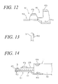
- FIG. 11 shows a top plan view of a connecting device 51 according to a second embodiment (first variant) of the present invention
- FIG. 12 shows a side view thereof.
- the cup-shaped solder connector portion 43 is replaced by a flat-type solder connector portion 53.
- the flat-type solder connector portion 53 is put into contact with the connector portion 3 of transformer 1 along its length direction, and soldered.
- the flat-type solder connector portion 53 of the connecting device 51 of the second embodiment is very easily soldered to the connector portion 3 of transformer 1. Further, the flat-type solder connector portion 53 of the connecting device 51 of the second embodiment has a simple, substantially flat shape. The shape of the connecting device 51 constructed therewith can be simplified accordingly, and manufactured more easily.
- FIG. 15 is a top plan view of a connecting device 61 according to a third embodiment (second variant) of the present invention, while FIG. 16 shows a side view thereof.
- the cup-shaped solder connector portion 43 of the first embodiment is replaced by a lip-type solder connector portion 63 comprising a pair of lips 63a and 63b extending in parallel from the edge of the cramping connector portion 41.
- the lip-type solder connector portion 63 comprises a link portion 63c which leads to the edge of cramping connector portion 41, and a pair of flat lips 63a and 63b.
- the latter is formed by bending each lateral end of the link portions 63c downwardly (or upwardly).
- Both lips 63a and 63b protrude forward (in the insertion direction of the noise-suppressing electrical cable 11) from the link portion 63c. They face each other along their longitudinal direction over a distance slightly greater than the diameter of connector portion 3 of transformer 1.
- the connector portion 3 of transformer 1 is flanked by the respective lips 63a and 63b of the lip-type solder connector portion 6, and fixed thereto as it is, whereby the connecting device 61 of the third embodiment is connected to the transformer 1.
- the connector portion 3 of transformer 1 is interposed between a pair of lips 63a and 63b of the lip-type solder connector portion 63 of the connecting device 61 of third embodiment, and they are soldered as they stand.
- the connector portion 3 of transformer 1 and the lip-type solder connector portion 63 are positioned as desired beforehand, the soldering process is easily carried out.
- the pair of lips 63a and 63b are soldered while flanking the connector portion 3 of transformer 1, the mechanical strength of the connecting portion is enhanced.
- a high-voltage electrical cable is connected to a transformer through an inventive connecting device.
- the coiled-type high-voltage noise-suppressing cable can be used as a high-voltage electrical cable, resulting in a further enhanced noise suppression effect.
- the connections among the connecting device, the coiled-type high-voltage noise-suppressing cable and the transformer are made by a simple process such as cramping or soldering. As a result, the coiled-type high-voltage noise-suppressing cable and the transformer can be connected easily and reliably.
- the solder connector portion of connecting device is in the form of a cup provided with a through hole in its base center.
- a connector portion of the transformer such as a rod-shaped terminal portion 3 is then passed through the through hole from the base side of cup-shaped solder connector portion, inserted thereinto, and soldered in this state.
- the solder forms a mass in the solder connector portion, the latter and the rod-shaped terminal portion are firmly soldered.
- the soldering process is easily carried out by dripping fused solder from above the solder connector portion. The soldering process can thus be greatly simplified.
- the surface of the solder connector portion of connecting device is put into contact with the length direction of a connector portion of transformer 1 such as a rod-shaped terminal portion 3, and are fixed by soldering.
- the soldering process can thus be carried out easily.
- the solder connector portion of the connecting device is comprised of a simple, substantially flat plate.
- a connector portion of the transformer 1, such as a rod-shaped terminal portion 3, is inserted between a pair of lips provided in the solder connector portion of the connecting device.
- the connector portion of transformer 1 and the pair of lips of the connecting device are soldered in this state, so that the connector portion of the transformer and the solder connector portion of the connecting device can be positioned properly.
- the cramping connector portion of connecting device comprises a first barrel portion, in which the coiled portion, prepared by baring the end portion of coiled-type high-voltage noise-suppressing cable, is held by press-fitting.
- the cramping connector portion further comprises a second barrel portion, in which the coiled-type high-voltage noise-suppressing cable is held by cramping from above its coating. In this manner, the coiled-type high-voltage noise-suppressing cable is firmly and reliably press-connected to the connecting device.
Landscapes
- Details Of Connecting Devices For Male And Female Coupling (AREA)
- Connections Effected By Soldering, Adhesion, Or Permanent Deformation (AREA)
Abstract
Description
whereby the transformer is connected and fixed to the coiled-type high-voltage noise-suppressing cable via the connecting device.
Claims (7)
- A metallic connecting device (13) for connecting a high-voltage electrical cable (5) to a transformer (1) having a connector portion (3) from which a high electrical voltage is outputted, the high-voltage electrical cable (5) including a coiled-type high-voltage noise-suppressing cable (11) including at least:characterised in that said metallic connecting device (13) comprises:a core element (21) containing a magnetic material;a coiled portion (25) including at least a conductive wire (23) through which the high electrical voltage is passed, the conductive wire (23) being wound around the core element (21); anda coating (33) covering the coiled portion (25);a cramping connector portion (41) adapted for press-fitting the coiled-type high-voltage noise-suppressing cable (11); anda solder connector portion (43) formed in extension of said cramping connector portion (41) and adapted for connecting to the connector portion (3) of the transformer (1) by soldering.
- The metallic connecting device according to claim 1, wherein the transformer (1) is provided with an electronic part including a rod-shaped terminal portion, wherein the connector portion (3) of the transformer (1) is comprised of the rod-shaped terminal portion, said solder connector portion (43) of said connecting device (13) is substantially in the form of a cup having a base with a through hole (43a), and wherein the rod-shaped terminal portion extends through said through hole (43a), and is connectable and securable to said solder connector portion (43) by soldering.
- The metallic connecting device (13) according to claim 1, wherein the transformer (1) is provided with an electronic part including a rod-shaped terminal portion, wherein the connector portion (3) of the transformer (1) is comprised of the rod-shaped terminal portion, said solder connector portion (43) of said connecting device (13) is comprised of a substantially flat plate which is placed into contact with the rod-shaped terminal portion along the length direction thereof, and wherein the rod-shaped terminal portion is connectable and securable to said solder connector portion (43) by soldering.
- The metallic connecting device according to claim 1, wherein the transformer (1) is provided with an electronic part including a rod-shaped terminal portion, wherein the connector portion (3) of the transformer (1) is comprised of the rod-shaped terminal portion, said solder connector portion (43) of said connecting device (13) is comprised of a pair of lips extending substantially in parallel, between which the rod-shaped terminal portion is inserted, and wherein the rod-shaped terminal portion is connectable and securable to said solder connector portion (43) by soldering.
- The metallic connecting device (13) according to any one of claims 1 to 4, wherein the coiled-type high-voltage noise-suppressing cable (11) comprises an end portion, the end portion being stripped of the coating (33) so that the coiled portion (25) is exposed, and wherein said cramping connector portion (41) comprises a first barrel portion (41a) configured to receive the coiled portion (25) of the coiled-type high-voltage noise-suppressing cable (11) in press-fit engagement, and a second barrel portion (41b) configured to receive the coiled-type high-voltage noise-suppressing cable (11) in cramped engagement with the coating (33).
- The metallic connecting device according to claim 5, wherein said second barrel portion (41b) comprises a base wall having a detent (41c) formed thereon.
- A method of connecting a transformer (1) containing a connector portion (3) to a high-voltage electrical cable (5) having an end portion, said method comprising the steps of:preparing a coiled-type high-voltage noise-suppressing cable (11) used as a high-voltage electrical cable (5), said coiled-type high-voltage noise-suppressing electrical cable (11) comprising:a core element (21) containing a magnetic material;a coiled portion (25) including a conductive wire (23) through which a high electrical voltage is passed, said conductive wire (23) being wound around said core element (21); anda coating (33) covering said coiled portion (25);stripping said end portion of said coating (33) so that said coiled portion (25) is exposed;preparing a metallic connecting device (13) comprising:a cramping connector portion (41) adapted for press-fitting said coiled-type high-voltage noise-suppressing cable (11);a solder connector portion (43) provided in extension of said cramping connector portion (41) and adapted for connecting said connector portion (3) of said transformer (1) to said end portion of said coiled-type high-voltage noise-suppressing cable (11) by soldering; andpress-fitting said coiled-type high-voltage noise-suppressing cable (11) in said cramping connector portion (41), and connecting and fixing said end portion of said coiled-type high-voltage noise-suppressing cable (11) to said connector portion (3) of said transformer (1) by soldering at said solder connector portion (43);whereby said transformer (1) is connected and fixed to said coiled-type high-voltage noise-suppressing cable (11) via said metallic connecting device (13).
Applications Claiming Priority (2)
| Application Number | Priority Date | Filing Date | Title |
|---|---|---|---|
| JP11019629A JP2000223168A (en) | 1999-01-28 | 1999-01-28 | Connection member, and connecting method of transformer to high-voltage wire |
| JP1962999 | 1999-01-28 |
Publications (2)
| Publication Number | Publication Date |
|---|---|
| EP1024558A2 true EP1024558A2 (en) | 2000-08-02 |
| EP1024558A3 EP1024558A3 (en) | 2002-01-30 |
Family
ID=12004504
Family Applications (1)
| Application Number | Title | Priority Date | Filing Date |
|---|---|---|---|
| EP00400219A Withdrawn EP1024558A3 (en) | 1999-01-28 | 2000-01-28 | Connecting device for high-voltage cable |
Country Status (4)
| Country | Link |
|---|---|
| US (1) | US6335489B1 (en) |
| EP (1) | EP1024558A3 (en) |
| JP (1) | JP2000223168A (en) |
| CA (1) | CA2296820C (en) |
Cited By (2)
| Publication number | Priority date | Publication date | Assignee | Title |
|---|---|---|---|---|
| DE202009006807U1 (en) * | 2009-05-11 | 2010-09-23 | Bremi Fahrzeug-Elektrik Gmbh + Co. Kg | connection cable |
| EP2166546A3 (en) * | 2008-09-19 | 2011-01-26 | Panasonic Corporation | Reactor unit with an electric connector |
Families Citing this family (4)
| Publication number | Priority date | Publication date | Assignee | Title |
|---|---|---|---|---|
| CN102260522A (en) * | 2011-06-21 | 2011-11-30 | 沈阳新电脱盐设备制造厂 | High-voltage introduction connecting device for electrical desalting tank |
| CN102856679A (en) * | 2011-06-30 | 2013-01-02 | 鸿富锦精密工业(深圳)有限公司 | Connecting wire fixing device |
| CN102856678A (en) * | 2011-06-30 | 2013-01-02 | 鸿富锦精密工业(深圳)有限公司 | Connecting wire fixing structure and connecting wire combination |
| JP7074399B2 (en) * | 2018-05-02 | 2022-05-24 | 住鉱テック株式会社 | Terminal crimping method |
Family Cites Families (13)
| Publication number | Priority date | Publication date | Assignee | Title |
|---|---|---|---|---|
| BE549349A (en) * | 1955-07-07 | |||
| US3596236A (en) * | 1969-04-03 | 1971-07-27 | Shlesinger Jr Bernard E | Deformable electrical connector for clamping conductors |
| US4199211A (en) * | 1978-12-18 | 1980-04-22 | Kidder Kent A | Wire connector |
| JPS6319710A (en) * | 1986-07-14 | 1988-01-27 | 矢崎総業株式会社 | High-voltage resistance wire for noise prevention and its manufacturing method |
| JPH0422548Y2 (en) * | 1988-06-09 | 1992-05-22 | ||
| DE3840014C2 (en) * | 1988-11-26 | 1997-02-06 | Kabelmetal Electro Gmbh | Process for producing an electrically conductive connection with a flat conductor |
| US5532433A (en) * | 1991-11-13 | 1996-07-02 | Yazaki Corporation | Waterproof-type terminal connection structure and method of producing same |
| JP2578848Y2 (en) | 1992-12-25 | 1998-08-20 | 住友電装株式会社 | Terminal cap and structure for attaching terminal cap to terminal |
| JPH06269929A (en) | 1993-03-25 | 1994-09-27 | Matsushita Electric Works Ltd | Method for connecting nichrome of surface heater |
| JPH0680263U (en) * | 1993-04-27 | 1994-11-08 | 矢崎総業株式会社 | Crimp terminal |
| JPH0817249A (en) * | 1994-06-30 | 1996-01-19 | Sumitomo Wiring Syst Ltd | Coil type noise eliminating high voltage resistance electric wire |
| JPH08281753A (en) | 1995-04-13 | 1996-10-29 | Honda Motor Co Ltd | Heater for injection nozzle |
| DE69622668T2 (en) * | 1995-12-01 | 2003-03-13 | Sumitomo Wiring Systems, Ltd. | A wire end connector assembly |
-
1999
- 1999-01-28 JP JP11019629A patent/JP2000223168A/en not_active Abandoned
-
2000
- 2000-01-24 CA CA002296820A patent/CA2296820C/en not_active Expired - Fee Related
- 2000-01-28 US US09/493,680 patent/US6335489B1/en not_active Expired - Fee Related
- 2000-01-28 EP EP00400219A patent/EP1024558A3/en not_active Withdrawn
Cited By (2)
| Publication number | Priority date | Publication date | Assignee | Title |
|---|---|---|---|---|
| EP2166546A3 (en) * | 2008-09-19 | 2011-01-26 | Panasonic Corporation | Reactor unit with an electric connector |
| DE202009006807U1 (en) * | 2009-05-11 | 2010-09-23 | Bremi Fahrzeug-Elektrik Gmbh + Co. Kg | connection cable |
Also Published As
| Publication number | Publication date |
|---|---|
| CA2296820A1 (en) | 2000-07-28 |
| CA2296820C (en) | 2004-06-01 |
| JP2000223168A (en) | 2000-08-11 |
| EP1024558A3 (en) | 2002-01-30 |
| US6335489B1 (en) | 2002-01-01 |
Similar Documents
| Publication | Publication Date | Title |
|---|---|---|
| US5496968A (en) | Shielded cable connecting terminal | |
| KR20100129739A (en) | Hoop member, inner conductor terminal and coaxial connector manufacturing method | |
| US20060205251A1 (en) | Cable plug | |
| EP2887366A1 (en) | Ignition coil and method of assembly | |
| KR101697721B1 (en) | Terminal connection comprising an hf conductor, in particular for a coaxial cable, and method for producing said terminal connection | |
| JP2002530821A (en) | Connection device | |
| JP2009159650A (en) | Coil device lead wire drawing structure | |
| US4659164A (en) | Diode connector | |
| CA2296820C (en) | Connecting device for high-voltage cable | |
| US3605077A (en) | Wire stop and wire guide in terminals and connectors | |
| IE53452B1 (en) | Electrical plug connector | |
| JP6587243B1 (en) | Connection devices, plugs and sockets | |
| EP0090538A2 (en) | Right angle coaxial connector | |
| US20020149455A1 (en) | Proximity switch and a cable terminal part unit and a process for its manufacture | |
| US6149460A (en) | RF plug connection system and method for assembling the RF plug connection system | |
| US5778086A (en) | Electronic device connection terminal | |
| US7008273B2 (en) | Cable connector assembly and method of making the same | |
| EP0555716A1 (en) | Insulated electrical terminal and method of fabricating same | |
| US20050250381A1 (en) | Connector for a coaxial cable | |
| US1645539A (en) | Insulated-conductor terminal | |
| US20240106138A1 (en) | Electric connecting apparatus | |
| US7007381B2 (en) | Method of attaching an electric conductor to an electrically conductive terminal via a telescoping sleeve | |
| GB2196489A (en) | Electric motor | |
| JPH02228198A (en) | Method of connection of electric terminal and lead wire for loudspeaker | |
| JPH05205801A (en) | High-voltage connecting device |
Legal Events
| Date | Code | Title | Description |
|---|---|---|---|
| PUAI | Public reference made under article 153(3) epc to a published international application that has entered the european phase |
Free format text: ORIGINAL CODE: 0009012 |
|
| 17P | Request for examination filed |
Effective date: 20000207 |
|
| AK | Designated contracting states |
Kind code of ref document: A2 Designated state(s): AT BE CH CY DE DK ES FI FR GB GR IE IT LI LU MC NL PT SE |
|
| AX | Request for extension of the european patent |
Free format text: AL;LT;LV;MK;RO;SI |
|
| PUAL | Search report despatched |
Free format text: ORIGINAL CODE: 0009013 |
|
| STAA | Information on the status of an ep patent application or granted ep patent |
Free format text: STATUS: THE APPLICATION HAS BEEN WITHDRAWN |
|
| AK | Designated contracting states |
Kind code of ref document: A3 Designated state(s): AT BE CH CY DE DK ES FI FR GB GR IE IT LI LU MC NL PT SE |
|
| AX | Request for extension of the european patent |
Free format text: AL;LT;LV;MK;RO;SI |
|
| 18W | Application withdrawn |
Withdrawal date: 20011207 |