EP1024670A2 - Projecteur vidéo - Google Patents
Projecteur vidéo Download PDFInfo
- Publication number
- EP1024670A2 EP1024670A2 EP00250029A EP00250029A EP1024670A2 EP 1024670 A2 EP1024670 A2 EP 1024670A2 EP 00250029 A EP00250029 A EP 00250029A EP 00250029 A EP00250029 A EP 00250029A EP 1024670 A2 EP1024670 A2 EP 1024670A2
- Authority
- EP
- European Patent Office
- Prior art keywords
- color
- video
- light
- light flux
- selection scanning
- Prior art date
- Legal status (The legal status is an assumption and is not a legal conclusion. Google has not performed a legal analysis and makes no representation as to the accuracy of the status listed.)
- Granted
Links
- 230000004907 flux Effects 0.000 claims abstract description 91
- 230000003287 optical effect Effects 0.000 claims abstract description 59
- 238000003384 imaging method Methods 0.000 claims abstract description 31
- 238000009826 distribution Methods 0.000 claims abstract description 25
- 238000001914 filtration Methods 0.000 claims abstract description 7
- 230000000903 blocking effect Effects 0.000 claims description 17
- 239000011159 matrix material Substances 0.000 claims description 7
- 230000010287 polarization Effects 0.000 claims description 6
- 239000004973 liquid crystal related substance Substances 0.000 claims description 4
- 238000004519 manufacturing process Methods 0.000 abstract description 6
- 230000000149 penetrating effect Effects 0.000 description 16
- 239000003086 colorant Substances 0.000 description 13
- 238000010586 diagram Methods 0.000 description 11
- 239000000203 mixture Substances 0.000 description 9
- 230000005540 biological transmission Effects 0.000 description 3
- 238000000034 method Methods 0.000 description 3
- 238000001816 cooling Methods 0.000 description 2
- 230000003247 decreasing effect Effects 0.000 description 2
- 239000011521 glass Substances 0.000 description 2
- 239000002184 metal Substances 0.000 description 2
- 238000005192 partition Methods 0.000 description 2
- 230000035515 penetration Effects 0.000 description 2
- 239000011248 coating agent Substances 0.000 description 1
- 238000000576 coating method Methods 0.000 description 1
- 239000002131 composite material Substances 0.000 description 1
- 150000001875 compounds Chemical class 0.000 description 1
- 238000000151 deposition Methods 0.000 description 1
- 239000005357 flat glass Substances 0.000 description 1
- 229910052736 halogen Inorganic materials 0.000 description 1
- 150000002367 halogens Chemical class 0.000 description 1
- 238000010030 laminating Methods 0.000 description 1
- 229910001507 metal halide Inorganic materials 0.000 description 1
- 150000005309 metal halides Chemical class 0.000 description 1
- 230000002093 peripheral effect Effects 0.000 description 1
- 230000005855 radiation Effects 0.000 description 1
Images


Classifications
-
- H—ELECTRICITY
- H04—ELECTRIC COMMUNICATION TECHNIQUE
- H04N—PICTORIAL COMMUNICATION, e.g. TELEVISION
- H04N9/00—Details of colour television systems
- H04N9/12—Picture reproducers
- H04N9/31—Projection devices for colour picture display, e.g. using electronic spatial light modulators [ESLM]
- H04N9/3102—Projection devices for colour picture display, e.g. using electronic spatial light modulators [ESLM] using two-dimensional electronic spatial light modulators
- H04N9/3111—Projection devices for colour picture display, e.g. using electronic spatial light modulators [ESLM] using two-dimensional electronic spatial light modulators for displaying the colours sequentially, e.g. by using sequentially activated light sources
- H04N9/3114—Projection devices for colour picture display, e.g. using electronic spatial light modulators [ESLM] using two-dimensional electronic spatial light modulators for displaying the colours sequentially, e.g. by using sequentially activated light sources by using a sequential colour filter producing one colour at a time
Definitions
- the present invention relates to a video projector, and more particularly to a video projector far time-dividing a light from a white-light source to light fluxes having given colors to be displayed.
- a video projector for displaying a colored image there has been known a video projector which time-divides light from a white-light source into three primary-colored light fluxes, thereafter modulates the intensities of the three primary-colored light fluxes subjected to time division and combines them for display.
- Japanese patent laid-open publication No. Sho 63-316590 discloses a color selection scanning device for time-dividing light from a white-light source into three primary-colored light fluxes. There is disclosed a video projector using a color wheel in which three colored translucent filters for transmitting each colored light flux, i.e., a red-colored light flux, a green-colored light flux and a blue-colored light flux therethrough are radialized in a circle, and the technique shown in this publication will be described as prior art.
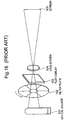
- Fig. 16 is a perspective view showing the structure of a conventional video projector.
- Light from an optical source 101 enters a filter plate 102 so that a red-colored light flux, a green-colored light flux and a blue-colored light fluxesequentially penetrate in synchronism with a rotation of the filter plate 102.
- Each colored light flux that has penetrated the filter plate 102 enters a flat display 103.
- the flat display 103 displays images associated with a red-colored light video signal, a green-colored light video signal and a blue-colored light video signal in synchronism with switching between the red color, the green color and the blue color of the filter plate 102 and modulates intensities of the incident light fluxes for each pixel.
- the penetrated light fluxes from the flat display 103 are magnified and projected on a screen 105 through a lens system 104.
- the velocity and phase of rotation of the filter plate 102 are controlled in such a manner that colors of the incident light fluxes sequentially change from the upper side of the filter plate 102 downwards in synchronism with the image on the flat display 103 being sequentially scanned from the lower side every one line upwards in the horizontal direction.
- a color-projected image is obtained by using the filter plate in which the three elementary colors are radialized as the color selection scanning device.
- the color purity of an image projected on the screen 105 is low. That is because the optical source 101 is not an ideal point optical source that is infinitely small in size and has a finite largeness expanding to a predetermined range. Light fluxes radiated from the optical source 101 thus contain various angle components, and complete parallel light beams cannot be obtained.
- the filter plate 102 and the flat display 103 are provided with a predetermined distance therebetween, a color border formed by the filter plate 102 spreads on a surface of the flat display 103 and adjacent colored lights on the filter plate 102 are mixed.
- Fig. 17 is a partially-enlarged front view showing the filter plate 102 in the video projector illustrated in Fig. 16.
- a color border 102B of the filter plate 102 is horizontal on a horizontal line H running through the rotational axis of the filter plate 102, the inclination of the color border 102B of the filter plate 102 with respect to the horizontal line H becomes large as the color border 102B is separated from the horizontal line H, and a color-mixed area R in which a color of the penetrated light from the filter plate 102 does not coincide with a color modulated by the flat display 103, generating mixture with other colors in the color-mixed area R.
- reduction in color shading of the projected image involves decrease in brightness of the projected image. That is because provision of a light blacking portion 102X in a predetermined angle range in the radial direction around the color border 102B of the filter plate 102 for the purpose of avoiding penetration of the light in the color-mixed area R causes the light blocked by the light blocking portion 102X to be disused, thereby reducing the efficiency of the light availability.
- An object of the present invention is to provide a video projector which can obtain high brightness of a projected image, high color purity and low color shading and which can be downsized and reduce the manufacturing cost.
- a video projector includes: an optical source, a color selection scanning device for selectively filtering a color of a light from the optical source to generate a light flux having a specific color in synchronism with a supplied video signal; a video displaying device for modulating the intensity of the light flux in synchronism with the video signal pixel by pixel to form a modulated image responsive to the video signal; an imaging lens disposed between the color selection scanning device and the video displaying device, for imaging the intensity distribution and the color distribution of the light flux outgoing from the color selection scanning device on a surface of the video displaying device; and a projecting lens for projecting the modulated image formed by the video displaying device.
- a video projector ha has an optical source; a color selection scanning device for selectively filtering a color of a light from the optical source to generate a specific color in synchronism with a supplied video signal; a color separating device for separating a light flux transmitted through or reflected on the color selection scanning device into first and second light fluxes having different wavelengths; a color combining device for combining the first and second light fluxes separated by the color separating device; a first video displaying device disposed between the color separating device and the color combining device, for modulating the intensity of the first light flux in synchronism with the video signal pixel by pixel to form a first modulated image responsive to the video signal; a second video displaying device disposed between the color separating device and the color combining device, for modulating the intensity of the second light flux in synchronism with the video signal pixel by pixel to form a second modulated image responsive to the video signal; a first imaging lens disposed between the color separating device
- each colored light flux subjected to time division manner by the color selection scanning device can be precisely imaged on a surface portion of the video displaying device, thereby improving the color purity of the projected image without generating color mixture on the surface of the video displaying device.
- the size of a virtual image of the video display device on the surface of the color section scanning device can be arbitrarily set by appropriately selecting each distance between the color selection scanning device, the imaging lens and the video displaying device and the focal distance of the imaging lens and changing the magnification of the imaging lens.
- the radiation efficiency of the color selection scanning device can be improved by setting the magnification of the imaging lens to less than 1 and increasing the size of a virtual image of the video displaying device on the surface of the color selection scanning device, thus suppressing an increase in temperature.
- the color selection scanning device which is small in size can be used, resulting in realization of miniaturization of the apparatus and reduction in the manufacturing cost.
- color mixture is not generated in the border area even if the light blocking portion is provided in the color border area of the color selection scanning device, and the width of the light blocking portion can be greatly reduced as compared with prior art, further improving the brightness of the projected image.
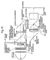
- the video projector includes an optical source 1; optical integrators 61 and 62; a polarization converting optical system 8; a condenser lens 71; a color wheel 21; a relay lens 72; a condenser lens 73; a liquid crystal display (hereinafter abbreviated to "LCD") panel 4; and a projecting lens 5.
- the optical source 1 is composed of a metal halide lamp, a halogen lamp and the like and emits white-colored light.
- the optical integrators 61 and 62 are a lens array forming a group of multiple lenses on a flat glass, and the light from the optical source 1 is ideally dispersed into multiple small optical sources by using this lens group to uniformly illuminate the color wheel 21.
- the polarization converting optical system 8 is constituted by a combination of a polarized beam splitter and a half-wave plate and aligns polarizing directions of outgoing light fluxes having unequal polarizing directions from the optical integrators 61 and 62 to a fixed direction to be emitted therefrom.
- the condenser lens 71 is constituted by combined use of one or more lenses and converges outgoing light fluxes from the polarization converting optical system 8 to efficiently enter into the relay lens 72.
- the color wheel 21 is an optical device which radializes red-colored light penetrating dichroic filter 21R, green-colored light penetrating dichroic filter 21G and blue-colored light penetrating dichroic filter 21B around the rotating shaft thereof and which connects a motor 23 to this rotating shaft so as to be capable of rotating around the rotational axis.
- the color wheel 21 is rotated in synchronism with scanning of the LCD panel 4 and sequentially transmits therethrough only each primary-colored light flux in the white-colored light from the optical source 1 in accordance with time division.
- respective fan-shaped end portions of the dichroic filter 21R, 21G and 21B may be directly bonded to each other to be integrally formed, or marginal portions of the respective dichroic filters 21R, 21G and 21B may be fitted in and bonded to a frame body such as a metal plate, a plastic plate and others for holding peripheral portions of the respective dichroic filters 21R, 21G and 21B so as to be integrally formed.
- the relay lens 72 consists of combined use of one or more lenses and the like and precisely images an intensity distribution and a color distribution of light flux outgoing from the color wheel 21 on the surface of the LCD panel 4.
- the condenser lens 73 consists of the combined use of one or more lenses and the like and converges the transmitted light fluxes from the relay lens 72 to be efficiently incident on the projecting lens 5.
- the LCD panel 4 is composed of a non-colored dot-matrix LCD device and the like having no color filter.
- the LCD panel 4 sequentially receives a red-colored light video signal, a green-colored light video signal and a blue-colored light video signal in time-division manner to modulate the intensity of the incoming light for each pixel in accordance with the supplied video signal, namely, control the quantity of penetration of the light to be emitted therefrom.
- the projecting lens 5 has a lens structure in which a plurality of lenses are combined and projects the transmitted light from the LCD panel 4 on the screen 99 in a magnified form.
- the screen 99 is provided in front of the projecting lens 5, and a projected image is displayed on the screen 99 in a magnified form.
- Fig. 3 is an explanatory diagram showing the arrangement of an optical system in the video projector according to the Fig. 1 embodiment.
- This embodiment is characterized in that provision of the relay lens 72 between the color wheel 21 and the LCD panel 4 enables the intensity distribution and the color distribution of the light flux outgoing from the color wheel 21 to be precisely imaged on the surface of the LCD panel 4. Blurring or color mixture cannot, therefore, occur on the color border of the incident light on the surface of the LCD panel 4, and coincidence of the scanning border of the LCD panel 4 with the color border of the incident light can be maintained.
- a distance S1 between the color wheel 21 and the relay lens 72, another distance 52 between the relay lens 72 and the LCD panel 4 and a focal distance of the relay lens 72 are selected so as to image the intensity distribution and the color distribution of the light flux outgoing from the color wheel 21 on the surface of the LCD panel 4.
- Another characteristic of this embodiment is that the distance S1 between the color wheel 21 and the relay lens 72 and the distance S2 between the relay lens 72 and the LCD panel 4 are set as (S2 ⁇ S1). Accordingly, a virtual image of the LCD panel 4 on the surface of the color wheel 21 is larger than the size of the LCD panel 4, and hence the compact LCD panel 4 can be used.
- Fig. 4 is an explanatory diagram showing the arrangement of an optical system in a video projector according to the second embodiment of the present invention.
- a characteristic of this embodiment lies in that the relay lens 72 is provided and (S2>S1) is set as opposed to Fig. 3.
- a virtual image of the LCD panel 4 on the surface of the color wheel 21 is smaller than the size of the LCD panel 4, thereby reducing the size of the color wheel 21 without changing the size of the LCD panel 4.
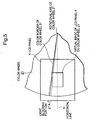
- a light blocking portion 21X (Fig. 5) is provided in the border area of the respective dichroic filters 21R, 21G and 21B of the color wheel 21 in order to prevent adjacent colors from being mixed.
- the light blocking portion 21X can be formed by a method such as provision of this supporting frame body extending to the border area of the respective dichroic filters 21R, 21G and 21B.
- Fig. 6 shows the third embodiment of the present invention.
- an electronic color filter 22 is used in place of the color wheel 21 in the first embodiment.
- the electronic color filter 22 is constituted by combined use of a color polarizing plate, a dot-matrix LCD device and a polarizing plate, and serves as an optical device which controls transmission/non-transmission of pixels with respect to each primary color in synchronism with the supplied video signal and is capable of changing colors of the transmitted light fluxes.
- Fig. 7A is an explanatory diagram showing the concept of scanning of the electronic color filter 22 in the video projector according to the Fig. 6 embodiment.
- Fig. 7B is an explanatory diagram showing the concept of scanning of the LCD panel 4 in the video projector according to the Fig. 6 embodiment.
- the electronic color filter 22 is sequentially scanned downwards every one line in the horizontal direction and changes the color of the transmitted light fluxes in synchronism with the LCD panel 4 being sequentially scanned upwards every one line in the horizontal direction.
- the direction of the scanning is opposed to that of the LCD panel 4 because the image is turned over due to transmission through the relay lens 72.
- the intensity distribution and the color distribution of the light flux outgoing from the electronic color filter 22 are imaged on the surface of the LCD panel 4 through the relay lens 72 as similar to the first embodiment.
- the video projector includes: an optical source 1; optical integrators 61 and 62; a polarization converting optical system 8; a condenser lens 71; a color wheel 21; a red-colored light penetrating dichroic mirror 91; relay lenses 72R and 72C; reflecting mirrors 93 and 94; condenser lenses 73R and 73C; LCD panels 4R and 4C; a cyan-colored light penetrating dichroic mirror 92; and a projecting lens 5. Only differences to the embodiment shown in Fig. 1 will be described herein.
- the relay lens 72R precisely images the intensity distribution on the surface of the LCD panel 4 with respect to only the red-colored light component having penetrated the red-colored light penetrating dichroic mirror 91 out of the light flux outgoing from the color wheel 21.
- the reflecting mirror 93 reflects thereon the transmitted light from the relay lens 72R.
- the condenser lens 73R consists of one or more lenses or the like and causes the reflected light from the reflecting mirror 93 to converge so as to be efficiently incident on the projecting lens 5.
- the LCD panel 4R is composed of a non-colored dot-matrix LCD device and the like having no color filter and subjects the incident light to the intensity modulation for each pixel in accordance with a supplied red-colored video signal so that the incident light outgoes therefrom.
- the relay lens 72C precisely images the intensity distribution and the color distribution on the surface of the LCD panel 4C with respect to the green-colored light flux and the blue-colored light flux reflected on the red-colored light penetrating dichroic mirror 91 out of the light flux outgoing from the color wheel 21.
- the reflecting mirror 94 reflects thereon the light flux having penetrated through the relay lens 72C.
- the condenser lens 73C consists of one or more lenses and causes the reflected light flux from the reflecting mirror 94 to converge so as to be efficiently incident on the projecting lens 5.
- the LCD panel 4C is composed of a non-colored dot-matrix LCD device and the like having no color filter.
- the LCD panel 4C sequentially receives a green-colored light video signal and a blue-colored light video signal in time-division manner and carries out the intensity modulation with respect to the incident light tar each pixel in accordance with the supplied video signal so that the incident light goes out therefrom.
- the cyan-colored light penetrating dichroic mirror 92 is an optical device which reflects the red-colored light flux thereon and transmits the cyan-colored light flux therethrough, and it combines the transmitted light fluxes from the LCD panels 4R and 4C.
- a yellow-colored light penetrating dichroic filter 21Y and a magenta-colored light penetrating dichroic filter 21M are alternately provided at right angle in a radial pattern around the rotating shaft, and a motor 23 is connected to the rotating shaft so that the wheel can rotate around the rotating shaft (Fig. 9A and B).
- the red-colored light penetrating dichroic mirror 91 transmits the red-colored light flux therethrough and reflects the blue-colored light flux thereon.
- the LCD panels 4R and 4C receive the red-colored light flux and the blue-colored light flux, respectively.
- the red-colored light video signal is supplied to the LCD panel 4R, and the green-colored light video signal and the blue-colored light video signal are alternately fed to the LCD panel 4C.
- the invention can be realized by using a plurality of LCD panels in this embodiment.
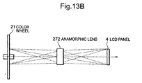
- the video projector of the embodiment in Fig. 10 substitutes an anamorphic lens 272 for the relay lens 72 in the video projector according to the first embodiment of the present invention shown in Fig. 1, and any other structure is the same with that shown in Fig. 1.
- the anamorphic lens 272 is constituted by arranging two achromatic prisms (prism obtained by laminating glasses having different refraction factors) before a composite lens and has a characteristic that the magnification of an image differs in the horizontal direction and the vertical direction on an image field or the focal distance of the same differs in the horizontal direction and the vertical direction.
- the outgoing light from the anamorphic lens 272 such a property that an enlargement ratio in a given direction is different from that in a direction orthogonal to this given direction on a flat surface vertical to the optical axis.
- a characteristic of this embodiment lies in that interposition of the anamorphic lens 272 between the color wheel 21 and the LCD panel 4 enables precise imaging of the transmitted light from the color wheel 21 on the surface of the LCD panel 4. Accordingly, blurring or color mixture does not occur on the color border of the incident light on the surface of the LCD panel 4 and coincidence of the scanning border of the LCD panel 4 with the color border of the incident light is maintained as similar to the first embodiment.
- anamorphic lens 272 is used to magnify the outgoing light from the color wheel 21 only in the vertical direction.
- the size of a virtual image of the LCD panel 4 on the surface of the color wheel 21 is smaller than the actual size of the LCD panel 4 in the vertical direction.
- the angle between the virtual image and the color border on the color wheel 21 becomes smaller, thereby further reducing the size of the light blocking portion 21X.
- the direction of the anamorphic lens 272 in which the enlargement ratio is high in the fifth embodiment is rotated 90 degrees around the optical axis.
- a characteristic of this embodiment lies in that the transmitted light from the color wheel 21 is precisely imaged on the surface of the LCD panel 4 by providing the anamorphic lens 272 between the color wheel 21 and the LCD panel 4.
- blurring or color mixture is thus not generated on the color border of the incident light on the surface of the LCD panel 4 and the coincidence of the scanning border of the liquid crystal display panel 4 with the color border of the incident light is maintained.
- Another characteristic of this embodiment lies in that the outgoing light from the color wheel 21 is enlarged only in the horizontal direction by the anamorphic lens 272.
- the size of the virtual image of the LCD panel 4 on the surface of the color wheel 21 is smaller than the actual size of the LCD panel 4.
- the size of the color wheel 21 can be reduced without changing the size of the LCD panel 4.
- the video projector of this embodiment substitutes anamorphic lenses 272R and 272C for the relay lenses 72R and 72C according to the fourth embodiment of the present invention. Description will be given only as to differences to Fig. 8 herein.
- Both anamorphic lenses 272R and 272C are provided in such a manner that their directions in which the enlargement ratio is high are matched with each other, and the respective outgoing light fluxes from the anamorphic lenses 272R and 272C are magnified or demagnified in the horizontal or vertical direction and precisely imaged on the respective LCD panels 4R and 4C.
- the outgoing light fluxes from the respective LCD panels 4R and 4C are combined by the cyan-colored light penetrating dichroic mirror 92 to be projected on the screen 99.
- this embodiment can have the characteristics of the foregoing fourth to sixth embodiments and can be realized by using a plurality of LCD panels, and the size of the color wheel 21 can be reduced without changing the size of the LCD panel 4.
- this type of optical integrator may be replaced by a rod integrator or a rod lens which is made of square-pole-shaped glass and obtains an outgoing light flux having a uniform intensity by internally reflecting an incident light flux for multiple times.
- the LCD panel 4, 4R, 4C and the electronic color filter 22 are used for modulating the intensity of a light flux pixel by pixel to form a modulated image responsive to the video signal in each of the above-described embodiments, it may be substituted by any optical device which is sequentially scanned in accordance with the video signal and modulates the intensity of an incident light flux to outgo therefrom.
- the green-colored light flux and the blue-colored light flux are both used by one LCD panel 4C in the fourth and seventh embodiments, but other arbitrary two colors may be used for one LCD panel, or an independent LCD panel may be used for each primary color. Also, a number of color partitions of the color wheel 21 is arbitrary.
- the color wheel 21 or the electronic color filter 22 is of a penetrating type for filtering light by penetrating a light flux having a required color in each of the above embodiments
- a color wheel or an electronic color filter which is of a reflecting type for filtering by reflecting a light flux having a required color may be used.
- it may be formed by depositing a multi-layered film having the reflecting characteristic on the surface thereof.
- a dot-matrix LCD device is used as the electronic color filter 22
- an LCD device having a striped pixel structure in the horizontal direction may be used.
- the combined use of the color polarizing plate, the dot-matrix LCD device and the polarizing plate is employed as the electronic color filter 22, but the electronic color filter 22 may be any device which can obtain a light flux having a given color while electrically scanning.
- the colored light fluxes transmitting through the color wheel 21 or the electronic color filter 22 are three, i.e., a red-colored light flux, a green-colored light flux and a blue-colored light flux, four or more colored light fluxes may be used. Also, a white-colored light flux may be used as a colored light flux to be selected.
- a number of partitions of the color wheel 21 in each of the above embodiments may be arbitrary.
- the high color purity of a projected image and the high fidelity of a screen image can be advantageously obtained. That is because provision of the imaging lens causes the color border formed by the color selection scanning device to be precisely imaged on the surface of the video displaying device, generating no blurring or color mixture.
- the increase in temperature of the color selection scanning device can be suppressed and the video projector which is suited for the continuous use and has the high durability can be realized. That is because the size of the color selection scanning device can be increased irrespective of the size of the video displaying device and discharge of the heat from the illuminating light is facilitated while the increase in temperature can be reduced. The cooling efficiency at the time of forcible cooling can be also enhanced.
- the color shading of a projected image can be advantageously suppressed while improving the brightness of the projected image. That is because the size of the color wheel is relatively large with respect to a virtual image of the video displaying device, and the border line between the respective colors of the color wheel approximates the horizontal line to reduce a size of an area in which color mixture occurs. Further, even if the light blocking portion is provided in the border areas of the respective colors of the color wheel, a superficial content of the light blocking portion can be greatly reduced as compared with the prior art.
- an anamorphic lens as the imaging lens advantageously leads to realization of a compact structure of the apparatus and reduction in the manufacturing cost. That is because the size of the color selection scanning device is relatively large with respect to a virtual image of the video displaying device, and the border line between the respective colors of the color selection scanning device thus approximates the horizontal line to reduce a size of an area in which color mixture occurs. In addition, even if the light blocking portion is provided in the border area of the respective colors of the color selection scanning device, a superficial content of the light blocking portion can be greatly reduced as compared with prior art.
Landscapes
- Engineering & Computer Science (AREA)
- Multimedia (AREA)
- Signal Processing (AREA)
- Projection Apparatus (AREA)
- Video Image Reproduction Devices For Color Tv Systems (AREA)
- Liquid Crystal (AREA)
- Transforming Electric Information Into Light Information (AREA)
- Devices For Indicating Variable Information By Combining Individual Elements (AREA)
- Control Of Indicators Other Than Cathode Ray Tubes (AREA)
Applications Claiming Priority (4)
| Application Number | Priority Date | Filing Date | Title |
|---|---|---|---|
| JP2096099 | 1999-01-29 | ||
| JP2096099 | 1999-01-29 | ||
| JP7128899 | 1999-03-17 | ||
| JP07128899A JP3299216B2 (ja) | 1999-01-29 | 1999-03-17 | 映像投写装置 |
Publications (3)
| Publication Number | Publication Date |
|---|---|
| EP1024670A2 true EP1024670A2 (fr) | 2000-08-02 |
| EP1024670A3 EP1024670A3 (fr) | 2005-03-09 |
| EP1024670B1 EP1024670B1 (fr) | 2014-06-25 |
Family
ID=26357961
Family Applications (1)
| Application Number | Title | Priority Date | Filing Date |
|---|---|---|---|
| EP00250029.6A Expired - Lifetime EP1024670B1 (fr) | 1999-01-29 | 2000-01-29 | Projecteur vidéo |
Country Status (3)
| Country | Link |
|---|---|
| US (1) | US6597409B1 (fr) |
| EP (1) | EP1024670B1 (fr) |
| JP (1) | JP3299216B2 (fr) |
Cited By (4)
| Publication number | Priority date | Publication date | Assignee | Title |
|---|---|---|---|---|
| EP1220548A3 (fr) * | 2000-12-28 | 2003-08-20 | Lg Electronics Inc. | Projecteur d'images en couleurs |
| EP1377073A3 (fr) * | 2002-06-25 | 2004-03-31 | Samsung Electronics Co., Ltd. | Unité d'éclairage avec roue à miroirs dichroiques et système d'affichage d'images comprenant une telle unité |
| EP1102496A3 (fr) * | 1999-11-19 | 2004-08-11 | Seiko Epson Corporation | Projecteur d'image couleur à panneau unique |
| CN102854730A (zh) * | 2012-07-19 | 2013-01-02 | 深圳市绎立锐光科技开发有限公司 | 光源系统及相关投影系统 |
Families Citing this family (20)
| Publication number | Priority date | Publication date | Assignee | Title |
|---|---|---|---|---|
| US6497485B1 (en) | 2000-01-20 | 2002-12-24 | Seiko Epson Corporation | Image projection system having uniform brightness |
| KR100381264B1 (ko) * | 2000-11-15 | 2003-05-01 | 엘지전자 주식회사 | 단판식 액정 프로젝터용 컬러 분리장치 |
| JP4628566B2 (ja) * | 2001-03-12 | 2011-02-09 | 三菱電機株式会社 | 画像投写装置 |
| JP2002287084A (ja) * | 2001-03-28 | 2002-10-03 | Fuji Photo Optical Co Ltd | 反射型液晶表示素子を用いた投写型画像表示装置 |
| US7070280B2 (en) * | 2001-07-04 | 2006-07-04 | Unaxis Balzers Aktiengesellschaft | Method for the generation of light of a given polarization state |
| JP2003216130A (ja) * | 2002-01-28 | 2003-07-30 | Nec Viewtechnology Ltd | ひずみ補正機能を備えた投写型表示装置 |
| JP4766841B2 (ja) * | 2003-09-08 | 2011-09-07 | 株式会社オートネットワーク技術研究所 | 車両に搭載されるカメラ装置及び車両周辺監視装置 |
| TWI236291B (en) * | 2004-01-15 | 2005-07-11 | Delta Electronics Inc | Color projection system |
| JP2005300746A (ja) * | 2004-04-08 | 2005-10-27 | Tokyo Univ Of Science | 情報表示装置 |
| US20060152686A1 (en) * | 2004-12-09 | 2006-07-13 | Serdar Yeralan | Short arc lamp light engine for video projection |
| JP4806932B2 (ja) * | 2005-01-19 | 2011-11-02 | カシオ計算機株式会社 | プロジェクタ |
| TWI269065B (en) * | 2005-05-02 | 2006-12-21 | Asia Optical Co Inc | Optical projection system |
| CN101454719B (zh) * | 2006-05-29 | 2010-06-23 | 松下电器产业株式会社 | 投射型显示装置 |
| JP4395792B2 (ja) | 2007-01-29 | 2010-01-13 | セイコーエプソン株式会社 | プロジェクタ |
| WO2010125681A1 (fr) * | 2009-04-30 | 2010-11-04 | Necディスプレイソリューションズ株式会社 | Affichage de projection |
| EP2842330B1 (fr) | 2012-04-13 | 2018-08-29 | Red.Com, Llc | Système de projecteur vidéo |
| US9025086B2 (en) * | 2012-04-13 | 2015-05-05 | Red.Com, Inc. | Video projector system |
| WO2014073043A1 (fr) * | 2012-11-07 | 2014-05-15 | 日立マクセル株式会社 | Dispositif d'affichage vidéo par projection |
| JP5938335B2 (ja) * | 2012-11-20 | 2016-06-22 | 日立マクセル株式会社 | 投写型映像表示装置 |
| JP6699897B2 (ja) * | 2016-11-11 | 2020-05-27 | 株式会社東芝 | 撮像装置、自動制御システム及びシステム |
Citations (2)
| Publication number | Priority date | Publication date | Assignee | Title |
|---|---|---|---|---|
| GB2324166A (en) | 1997-04-09 | 1998-10-14 | Samsung Electronics Co Ltd | Reflection projector having image generation unit and critical angle prism |
| US5863125A (en) | 1998-01-30 | 1999-01-26 | International Business Machines Corporation | High efficiency two-SLM projector employing total-internal-reflection prism |
Family Cites Families (16)
| Publication number | Priority date | Publication date | Assignee | Title |
|---|---|---|---|---|
| US2834254A (en) * | 1953-10-22 | 1958-05-13 | Du Mont Allen B Lab Inc | Electronic color filter |
| JPS62185456A (ja) | 1986-02-10 | 1987-08-13 | Nec Corp | 2色カラ−画像読取装置 |
| JPS63316590A (ja) | 1987-06-19 | 1988-12-23 | Hitachi Ltd | 投射形デイスプレイ |
| JP2675215B2 (ja) | 1991-10-29 | 1997-11-12 | 三菱電機株式会社 | カラー画像表示装置 |
| JPH05181135A (ja) | 1992-01-06 | 1993-07-23 | Canon Inc | 偏光照明装置及び該偏光照明装置を用いた投写表示装置 |
| US5371543A (en) * | 1993-03-03 | 1994-12-06 | Texas Instruments Incorporated | Monolithic color wheel |
| JPH06265894A (ja) | 1993-03-11 | 1994-09-22 | Teruki Fujiyama | カラ−表示装置 |
| KR950014336B1 (ko) | 1993-09-16 | 1995-11-24 | 엘지전자주식회사 | 화상투사장치 |
| JPH08140106A (ja) | 1994-10-31 | 1996-05-31 | Texas Instr Inc <Ti> | プロジエクタ装置 |
| US5517340A (en) * | 1995-01-30 | 1996-05-14 | International Business Machines Corporation | High performance projection display with two light valves |
| IL113796A0 (en) * | 1995-05-19 | 1995-08-31 | Unic View Ltd | Projector |
| JPH09304734A (ja) | 1996-05-15 | 1997-11-28 | Seiko Epson Corp | 偏光照明装置および投写型表示装置 |
| JPH10153755A (ja) | 1996-11-22 | 1998-06-09 | Teruki Fujiyama | 立体画像表示装置 |
| JPH10170869A (ja) | 1996-12-06 | 1998-06-26 | Seiko Epson Corp | 偏光照明装置および投写型表示装置 |
| JPH11184398A (ja) | 1997-12-19 | 1999-07-09 | Casio Comput Co Ltd | プロジェクタ |
| JPH11264953A (ja) | 1998-03-17 | 1999-09-28 | Minolta Co Ltd | カラー投影装置 |
-
1999
- 1999-03-17 JP JP07128899A patent/JP3299216B2/ja not_active Expired - Fee Related
-
2000
- 2000-01-29 EP EP00250029.6A patent/EP1024670B1/fr not_active Expired - Lifetime
- 2000-01-31 US US09/494,509 patent/US6597409B1/en not_active Expired - Lifetime
Patent Citations (2)
| Publication number | Priority date | Publication date | Assignee | Title |
|---|---|---|---|---|
| GB2324166A (en) | 1997-04-09 | 1998-10-14 | Samsung Electronics Co Ltd | Reflection projector having image generation unit and critical angle prism |
| US5863125A (en) | 1998-01-30 | 1999-01-26 | International Business Machines Corporation | High efficiency two-SLM projector employing total-internal-reflection prism |
Cited By (6)
| Publication number | Priority date | Publication date | Assignee | Title |
|---|---|---|---|---|
| EP1102496A3 (fr) * | 1999-11-19 | 2004-08-11 | Seiko Epson Corporation | Projecteur d'image couleur à panneau unique |
| EP1220548A3 (fr) * | 2000-12-28 | 2003-08-20 | Lg Electronics Inc. | Projecteur d'images en couleurs |
| US6802610B2 (en) | 2000-12-28 | 2004-10-12 | Lg Electronics Inc. | Image projector |
| EP1377073A3 (fr) * | 2002-06-25 | 2004-03-31 | Samsung Electronics Co., Ltd. | Unité d'éclairage avec roue à miroirs dichroiques et système d'affichage d'images comprenant une telle unité |
| US6869189B2 (en) | 2002-06-25 | 2005-03-22 | Samsung Electronics Co., Ltd. | Illumination optical unit employing dichroic mirror wheel and image display system including the illumination optical unit |
| CN102854730A (zh) * | 2012-07-19 | 2013-01-02 | 深圳市绎立锐光科技开发有限公司 | 光源系统及相关投影系统 |
Also Published As
| Publication number | Publication date |
|---|---|
| JP2000284361A (ja) | 2000-10-13 |
| US6597409B1 (en) | 2003-07-22 |
| JP3299216B2 (ja) | 2002-07-08 |
| EP1024670B1 (fr) | 2014-06-25 |
| EP1024670A3 (fr) | 2005-03-09 |
Similar Documents
| Publication | Publication Date | Title |
|---|---|---|
| EP1024670B1 (fr) | Projecteur vidéo | |
| JP4597298B2 (ja) | 複数の画像を投射するためのビデオ投射システム | |
| KR100533611B1 (ko) | 투영형 화상표시장치 | |
| US7042527B2 (en) | Field sequential display of color video picture with color breakup prevention | |
| JPH10123512A (ja) | 液晶表示装置用光源及びそれを用いたカラー液晶表示装置 | |
| JPH0460538A (ja) | カラー液晶表示装置 | |
| JPH0212124A (ja) | 表示装置 | |
| US5580144A (en) | Image projection device with suppressed moire | |
| JP2001249400A (ja) | 投射型表示装置 | |
| JP2003172900A (ja) | 画像投影表示装置、画像投影表示システム並びに画像投影表示方法 | |
| JPH10304284A (ja) | 液晶プロジェクタ | |
| KR960016286B1 (ko) | 투사형화상표시장치 | |
| JPH04100088A (ja) | 直視型画像表示装置 | |
| JPH09230301A (ja) | 投射型表示装置 | |
| US5184234A (en) | Stacked LCD color projector with equal path lengths | |
| JPH05257118A (ja) | 投写型カラー液晶表示システム | |
| JP2000098325A (ja) | 投写型カラー画像表示装置 | |
| JP2002139792A (ja) | 画像表示装置 | |
| JPH1152889A (ja) | 画像表示装置 | |
| JPH1165477A (ja) | プロジェクタ型カラー画像表示装置 | |
| JP3374452B2 (ja) | 投写型表示装置 | |
| US20050110955A1 (en) | Projection device | |
| JP3046503B2 (ja) | 投影型カラー液晶表示装置 | |
| JP5124679B2 (ja) | 投写型映像表示装置 | |
| WO2007093766A1 (fr) | Appareil de projection |
Legal Events
| Date | Code | Title | Description |
|---|---|---|---|
| PUAI | Public reference made under article 153(3) epc to a published international application that has entered the european phase |
Free format text: ORIGINAL CODE: 0009012 |
|
| AK | Designated contracting states |
Kind code of ref document: A2 Designated state(s): AT BE CH CY DE DK ES FI FR GB GR IE IT LI LU MC NL PT SE |
|
| AX | Request for extension of the european patent |
Free format text: AL;LT;LV;MK;RO;SI |
|
| RAP1 | Party data changed (applicant data changed or rights of an application transferred) |
Owner name: NEC VIEWTECHNOLOGY, LTD. |
|
| PUAL | Search report despatched |
Free format text: ORIGINAL CODE: 0009013 |
|
| AK | Designated contracting states |
Kind code of ref document: A3 Designated state(s): AT BE CH CY DE DK ES FI FR GB GR IE IT LI LU MC NL PT SE |
|
| AX | Request for extension of the european patent |
Extension state: AL LT LV MK RO SI |
|
| 17P | Request for examination filed |
Effective date: 20050310 |
|
| AKX | Designation fees paid |
Designated state(s): DE GB |
|
| RAP1 | Party data changed (applicant data changed or rights of an application transferred) |
Owner name: NEC DISPLAY SOLUTIONS, LTD. |
|
| 17Q | First examination report despatched |
Effective date: 20070928 |
|
| GRAJ | Information related to disapproval of communication of intention to grant by the applicant or resumption of examination proceedings by the epo deleted |
Free format text: ORIGINAL CODE: EPIDOSDIGR1 |
|
| GRAP | Despatch of communication of intention to grant a patent |
Free format text: ORIGINAL CODE: EPIDOSNIGR1 |
|
| GRAP | Despatch of communication of intention to grant a patent |
Free format text: ORIGINAL CODE: EPIDOSNIGR1 |
|
| INTG | Intention to grant announced |
Effective date: 20140102 |
|
| GRAS | Grant fee paid |
Free format text: ORIGINAL CODE: EPIDOSNIGR3 |
|
| GRAA | (expected) grant |
Free format text: ORIGINAL CODE: 0009210 |
|
| AK | Designated contracting states |
Kind code of ref document: B1 Designated state(s): DE GB |
|
| REG | Reference to a national code |
Ref country code: GB Ref legal event code: FG4D |
|
| REG | Reference to a national code |
Ref country code: DE Ref legal event code: R096 Ref document number: 60048626 Country of ref document: DE Effective date: 20140731 |
|
| PGFP | Annual fee paid to national office [announced via postgrant information from national office to epo] |
Ref country code: GB Payment date: 20141103 Year of fee payment: 16 |
|
| REG | Reference to a national code |
Ref country code: DE Ref legal event code: R097 Ref document number: 60048626 Country of ref document: DE |
|
| PGFP | Annual fee paid to national office [announced via postgrant information from national office to epo] |
Ref country code: DE Payment date: 20150129 Year of fee payment: 16 |
|
| PLBE | No opposition filed within time limit |
Free format text: ORIGINAL CODE: 0009261 |
|
| STAA | Information on the status of an ep patent application or granted ep patent |
Free format text: STATUS: NO OPPOSITION FILED WITHIN TIME LIMIT |
|
| 26N | No opposition filed |
Effective date: 20150326 |
|
| REG | Reference to a national code |
Ref country code: DE Ref legal event code: R119 Ref document number: 60048626 Country of ref document: DE |
|
| GBPC | Gb: european patent ceased through non-payment of renewal fee |
Effective date: 20160129 |
|
| PG25 | Lapsed in a contracting state [announced via postgrant information from national office to epo] |
Ref country code: DE Free format text: LAPSE BECAUSE OF NON-PAYMENT OF DUE FEES Effective date: 20160802 Ref country code: GB Free format text: LAPSE BECAUSE OF NON-PAYMENT OF DUE FEES Effective date: 20160129 |