EP1024711B1 - Maschine zum schälen, entkernen und zerschneiden von birnen - Google Patents
Maschine zum schälen, entkernen und zerschneiden von birnen Download PDFInfo
- Publication number
- EP1024711B1 EP1024711B1 EP98950312A EP98950312A EP1024711B1 EP 1024711 B1 EP1024711 B1 EP 1024711B1 EP 98950312 A EP98950312 A EP 98950312A EP 98950312 A EP98950312 A EP 98950312A EP 1024711 B1 EP1024711 B1 EP 1024711B1
- Authority
- EP
- European Patent Office
- Prior art keywords
- pear
- pears
- pliers
- machine according
- station
- Prior art date
- Legal status (The legal status is an assumption and is not a legal conclusion. Google has not performed a legal analysis and makes no representation as to the accuracy of the status listed.)
- Expired - Lifetime
Links
- 241000220324 Pyrus Species 0.000 title claims description 183
- 235000021017 pears Nutrition 0.000 title claims description 58
- 235000014443 Pyrus communis Nutrition 0.000 claims description 125
- 230000033001 locomotion Effects 0.000 claims description 30
- 230000007246 mechanism Effects 0.000 claims description 16
- 238000012546 transfer Methods 0.000 claims description 9
- 244000000626 Daucus carota Species 0.000 claims description 6
- 235000002767 Daucus carota Nutrition 0.000 claims description 6
- 210000000845 cartilage Anatomy 0.000 claims description 3
- XLYOFNOQVPJJNP-UHFFFAOYSA-N water Substances O XLYOFNOQVPJJNP-UHFFFAOYSA-N 0.000 claims description 3
- 244000027321 Lychnis chalcedonica Species 0.000 claims description 2
- 230000009471 action Effects 0.000 claims description 2
- 239000000654 additive Substances 0.000 claims description 2
- 230000008859 change Effects 0.000 claims description 2
- 230000000295 complement effect Effects 0.000 claims description 2
- 230000035515 penetration Effects 0.000 claims description 2
- 239000002699 waste material Substances 0.000 claims description 2
- 239000002131 composite material Substances 0.000 claims 2
- 230000005526 G1 to G0 transition Effects 0.000 claims 1
- 230000000712 assembly Effects 0.000 claims 1
- 238000000429 assembly Methods 0.000 claims 1
- 230000005484 gravity Effects 0.000 claims 1
- 235000013399 edible fruits Nutrition 0.000 description 3
- 230000000694 effects Effects 0.000 description 2
- 238000000034 method Methods 0.000 description 2
- 238000013459 approach Methods 0.000 description 1
- 230000001174 ascending effect Effects 0.000 description 1
- 230000005540 biological transmission Effects 0.000 description 1
- 230000002860 competitive effect Effects 0.000 description 1
- 230000005662 electromechanics Effects 0.000 description 1
- 230000008030 elimination Effects 0.000 description 1
- 238000003379 elimination reaction Methods 0.000 description 1
- 235000012027 fruit salads Nutrition 0.000 description 1
- 238000003780 insertion Methods 0.000 description 1
- 230000037431 insertion Effects 0.000 description 1
- 230000001788 irregular Effects 0.000 description 1
- 239000000463 material Substances 0.000 description 1
- 238000012545 processing Methods 0.000 description 1
- 238000003672 processing method Methods 0.000 description 1
- 230000001681 protective effect Effects 0.000 description 1
- 238000000926 separation method Methods 0.000 description 1
- 230000001360 synchronised effect Effects 0.000 description 1
- 238000009966 trimming Methods 0.000 description 1
Images


Classifications
-
- A—HUMAN NECESSITIES
- A23—FOODS OR FOODSTUFFS; TREATMENT THEREOF, NOT COVERED BY OTHER CLASSES
- A23N—MACHINES OR APPARATUS FOR TREATING HARVESTED FRUIT, VEGETABLES OR FLOWER BULBS IN BULK, NOT OTHERWISE PROVIDED FOR; PEELING VEGETABLES OR FRUIT IN BULK; APPARATUS FOR PREPARING ANIMAL FEEDING- STUFFS
- A23N4/00—Machines for stoning fruit or removing seed-containing sections from fruit, characterised by their stoning or removing device
- A23N4/12—Machines for stoning fruit or removing seed-containing sections from fruit, characterised by their stoning or removing device for coring fruit
- A23N4/14—Machines for stoning fruit or removing seed-containing sections from fruit, characterised by their stoning or removing device for coring fruit for apples, pears or the like
Definitions
- the present invention relates to a machine which is suited to perform automatically, and in a way which is industrially applicable, the following operations on pears:
- US 5,435,2308 corresponding to the closest prior art, discloses a pear processing method and apparatus including several mechanisms for properly orienting the pear prior to coring, peeling and seed celling.
- the pear After being oriented by a pair of orienting rolls, the pear is held with its stem directed downwardly, and is dropped into a transfer cup.
- the pear is trimmed by blossom trim means. Then, the feed cup rotates by 90° in order to impale the pear on the coring tube.
- the pear On this tube the pear is rotated, the stem of the pear is severed, the peeling is performed, and finally the seed cell of the pear is severed by seed celling knife means.
- the machine of the present application splits the pear on the same spindle used for seed celling. Instead, the machine of the above mentioned US patent requires a separate slice cup means.
- US-3,768,627 discloses an apparatus and method used only for orienting pears, wherein a trough support, which is inclined and has diverging walls, is employed.
- the side walls of the trough are spaced apart at the bottom, to receive the upper stretch of a belt. If a pear has its bulb end uppermost, it continues to travel uphill and no effect is produced. If the pear has its stem end uppermost, while travelling uphill on the inclined trough, it is rotated. The result is that all the pears are discharged from the trough with their butt ends foremost.
- FR-A-2,533,807 discloses a machine for orienting and displacing pears. There are disclosed means to orient the pears vertically, and inflatable means to hold them firmly inside cups provided on a rotating drum. The rotation of the drum enables to move the pears to successive stations, in order to perform different operations thereon.
- Said drum cannot be compared to the rotatable head of the present application, since it has no tubular tool to separate the core.
- US 3,211,201 discloses a machine which can perform pear stem end trimming, stemming, peeling, coring, and splitting.
- This machine does not perform any orientation of the pears, since the latter are placed stem-end-down by the operator himself.
- An object - even if not the only one -of the present invention, is to realize a machine allowing to perform automatically on the pears, from their feeding to the end-item, all operations required to obtain the end-item, so that the latter can be readily stored in a vase or the like, or used to prepare fruit-salads, etc.
- Said object is obtained by means of the automatized multiple station transfer machine of the present invention, comprising a plurality of stations, in each of which an operation is carried out, which follows the preceding one, and this being done from the feeding and orientation, until the final cutting into segments.
- the machine of the present invention is characterized in that it comprises the following principal elements:
- the machine operates as follows.
- the pears are taken out one at a time from a basin or cistern (1) and are lifted, by means of a stepped chain conveyor (2) having an intermittent motion, until they reach a position where they are seized by pliers (4) which transfer them on a second chain conveyor (Fig. 7), having also an intermittent motion.
- the chain conveyor (Fig. 7), which is characterized by elements insuring a horizontal positioning of the pears, but with their stem pointing in one direction (Fig. 13) or in the opposite one (Fig. 14), translates the pears towards a position, where they will be seized by second pliers (Figs. 8-9-10-11).
- Said second pliers after having seized each pear, orient it according to a vertical direction and with its stem always directed downwardly, irrespective of the orientation of the stem at the seizing time, that is whether it was oriented according to Fig. 13 or 14.
- the pear is also disposed in a very precise position and is released and handed over to a clamping and concentric locating device (Fig. 15).
- the device retains the pear by means of self-centering pliers , after receiving it, and orients its axis perfectly in the vertical direction.
- the aforesaid device rotates around its axis by 180 degrees (so that the pear is still vertically oriented but the stem is upwardly directed), and thereafter it moves downward, thrusting the pear in a tubular tool (57), which is coaxial with the longitudinal axis of the pear.
- Said tubular tool (57) separates a small core (in the shape of a circular "carrot"), from the pear body, said small core comprising, besides part of the central core, also the stem and the woody portion connecting the stem to the protective cartilage of the central core.
- Said tubular tool (57) is a structural part of a four-station rotatable head (Fig. 16) having an intermittent motion.
- the pear is thrust in the tubular tool, thereby obtaining a first partial removal of the core.
- the tubular tool is set in rotation, and using known tools the following operations are performed:
- the "carrot" is projected outward by a compressed air jet, from the interior of the tubular tool.
- the pear is taken off from the tubular tool (57) by means of the vice (Fig. 21) and is inserted on the tool (Fig. 22) for cutting it into segments and for removing its central core.
- the vice opens and moves to the tubular tool (57) in order to seize the successive pear; the vice closes again, displaces the new pear towards and onto the tool (of Fig. 22); at the same time it pushes the old pear on the wider portion of the blades (63-64), thereby separating it in two pieces or segments; the latter fall on a belt conveyor together with the central core and are taken away by it.
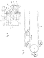
- the basin for containing the pears and water added with dissolved products for their conservation is denoted by 1, and the pears are taken off and lifted individually by means of the chain conveyor 2, provided with steps comprising two parts, 3/a and 3/b, wherein part 3/a is fixed and part 3/b is axially movable with respect to part 3/a.
- the width of the chain conveyor 2 is designed to contain only one pear. It moves intermittently in the direction indicated by arrow F1.
- step 3/b is located at a lower level with respect to step 3/a and has such a configuration allowing it to retain and carry only one pear; therefore, at the upper end of this "ladder", there arrives only a single pear for each step.
- step 3/b Only when reaching the upper end (denoted by 3/c), step 3/b lifts under the action of a cam, and "hands over" the pear to be grasped, to the pliers 4/a-b, which at this instant of time occupy position 3/c.
- the pears, carried individually by each step 3/a-b, are almost all disposed horizontally, but their stem is oriented in one direction or the opposite one.
- Fig. 3 shows a basin or cistern 1 associated with two chain conveyors 2, applicable to the case of a machine working simultaneously along two rows; in this case, also the devices to be described later on should be "duplicated".
- the pliers 4/a-b and all their structural elements, are supported by the basement or supporting structure of the basin.
- the pliers 4/a-b are characterized by:
- cam 14 When cam 14 rotates, it lifts and lowers the whole described mechanism; on the other hand, the actuator 15 serves almost only to displace the pliers 4/a-b to the right or to the left (besides lifting them slightly).
- the assembly is designed to satisfy the following two conditions:
- the chain conveyor 2, the pliers 4/a-b and the chain conveyor 16 perform movements which are linked together.
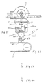
- the chain conveyor 16 (Fig. 7) is formed by a plurality of elements, one of them being shown in Figs. 4-5 and 6.
- rollers 17/a - 17/b each having a double taper converging at the center, are integral with a corresponding spindle 18/a- 18/b, which is supported by a respective connecting rod 19/a-19/b, pivotally connected to the pin 20.
- a bracket 21 and a connecting rod 22 are also pivotally connected to said pin 20, and the latter connecting rod is pivotally connected to the head portion 23 at its opposite end.
- Bracket 21 supports a small plate 24, integral with 25, which is vertically adjustable at 26.
- Spindles 18/a - 18/b have their ends slidable inside horizontal slots 27/a - 27/b obtained on the head portions 23; bracket 21 is integral with a pin 28 whose end slides inside a vertical slot 29, which is also obtained on the head 23; therefore, if the connecting rod 22 is lowered or lifted, rollers 17/a-17/b move away or approach each other, whereas the small plate 24 maintains its position with respect to rollers 17/a - 17/b, provided that the operator does not manually change the adjustment at 26.
- the connecting rod 22 is upwardly biased by elastic means (springs; pneumatic cylinders; etc) which are not shown.
- elastic means springs; pneumatic cylinders; etc
- slidable runners 30 integral therewith cooperate with the guide 31 connected to the machine bed through height-adjustable means (not shown). The adjustment is performed in conformity with the variation of the "gauge" of the pears to be processed.
- Pinions 32 are inserted or integrally formed on the spindles 18/a-18/b.
- the chain conveyor 16 which is formed by a certain number of the above described elements, moves intermittently in the direction of the arrow F2 (Fig. 7), and during each stop the rollers 17/a - 17/b rotate because the pinions 32 engage a motor driven chain.
- the only exception is given by the two end positions (where the pears are loaded, i.e. the position 3/d of Fig.2, and where they are unloaded, i.e. the position 3/e of Fig. 12).
- the rotation of the rollers 17/a - 17/b insures that the pears 33 supported by the rollers, are oriented so that their axis is horizontal, and that they will maintain this position.
- the height-adjusted small plate 24 insures that a pear which is released by the pliers 4/a-b (Fig. 2), does not wedge vertically between the rollers 17/a- 17/b, even if it falls with its stem directed downwardly.
- the spindles 18/a - 18/b are sufficiently long, so that, in the position indicated by the arrow F3, there will be a second pair of rollers 17/a - 17/b; and the second assembly -formed by the connecting rods, levers , head portions, etc. - will be located in the position indicated by the arrow F4 (Fig. 5).
- the head portions 23 are connected to the plates 70 which on their turn are connected to the chain conveyor 16.
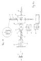
- the pears are taken off from the chain conveyor 16, at its end opposite to the loading end (Fig. 12) by means of self-centering pliers (Figs. 8-9-10-11); the latter comprise two equally sized L-shaped levers 34/a - 34/b respectively pivoted at 35/a - 35/b, the ends of which are adequately shaped for the intended purpose, on the "pear grasping side", whereas on the other sides, they are connected to the ends of a connecting rod 36.
- a linear pneumatic actuator 37 acting on one of the two levers, allows to clamp a pear in a self-centering manner.
- the levers 34/a - 34/b and the actuator 37 are supported by a plate 38, which is integral with a bevel gear 39, and the latter can selectively engage - under an adequate control- the bevel gear 40 or the bevel gear 41.
- the bevel gear 39 is idle on the shaft 42 whereas the gears 40 - 41 are integral with the supports 43 - 44.
- the shaft 46 can effect two different movements, which are transmitted by known mechanisms contained in the casing 47:
- the bevel gear 39 (which is coupled to 40 or 41) rotates by 1/4 of a complete revolution, so that the pliers 34/a-b which have taken a (horizontally disposed) pear from the chain conveyor of Figs. 10 and 12, will hold the pear in Fig. 11 with the axis of the pear being vertically oriented.
- a sensor which is located in an appropriate position on the chain conveyor 16, detects whether the pear is oriented as shown in Fig. 13 or Fig. 14, and passes a signal to the actuator inside the casing 47, in order to axially displace shaft 46 in the desired direction (engagement of 39 with 40 or 41), and in order to orient the pear always so that its stem is downwardly directed in the cnfiguration of Fig. 11. Therefore, the above described pliers do not only take the pear from the position 3/e of Fig. 10/12 and bring it to a position in which the axis is vertical (Fig. 11), but insure that the pears have always a downwardly oriented stem.
- Fig. 11 is not an orthogonal view of Fig. 10, instead, both views are on the same plane.
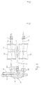
- Fig. 11 The pear in Fig. 11 is perfectly coaxial with a sleeve 49 of the device shown in Figs. 15 - 15/a - 17 and 18.
- Said device is characterized by two sleeves 49 having a hole in the form of a funnel (Fig. 15/a) and which are integrally formed on a body 50 applied to a shaft 51, wherein the latter can rotate intermittently by 180 degrees during each step (arrow F6).
- the motion is transmitted to shaft 51 by means of known mechanisms from inside the machine bed or structure 52.
- Said shaft 51 is mounted at its ends on supports 53 which slide along vertical guides 54, which on their turn are supported by brackets 55 integral with the machine bed.
- the funnels or sleeves 49 have a configuration (conical hole suited to receive the pear and discharge the stem) and dimensions (depending on the "gauge") such as to be able to receive the pear handed over by the pliers 34/a-b, and are (each) provided with self-centering pliers 56 (Fig. 15) which are identical to the pliers 34/a-b.
- Said pliers 56 have the function to put the pear in a vertical position, to maintain it in this position, and to hold it inside the funnel.
- a pear is released from the pliers 34/a-b.
- the pear slides inside the upper funnel 49 of the device (with a downwardly directed stem).
- the pliers 56 stop the movement of the pear axis and align the latter; then, the device rotates by 180 degrees and moves downward thrusting the pear in the tubular tool 57.
- the pliers 56 opens, thereby releasing (leaving) the pear on the tubular tool. Then, the device moves upward to receive another pear.
- the cycle is repeated periodically in synchronism with all the other machine components.
- the rotatable head (Figs. 16 - 16/a) is moved intermittently, each time by 90 degrees, and comprises four identical tubular tools 57 consisting of tubes with a chamfered end (Fig. 19), in order to facilitate their penetration in the axial direction, inside the pear (Fig. 1/a).
- said tubes are provided with two diametrically opposite fins 58 located in adequate positions, said fins acting as entrainment means when the tubular tool 57 is rotated, after they have penetrated the pulp of the pear.
- the first station corresponds to the vertically upward directed tubular tool 57 and coincides with the station where the above described device thrusts the pear in the tubular tool 57.
- the tubular tool 57 has a relatively small diameter; it axially crosses the whole pear, separating a "carrot" containing part of the flower, part of the central core, the stem and the woody part connecting the stem to the cartilage. enclosing the central core.
- the head rotates by 90 degrees and the pear is transferred to the second station, where the tubular tool 57 is rotated by known mechanisms, transmitting the motion through the shaft 59, from driving means located inside the machine bed 52.
- different operations are performed on the pear according to known means and known techniques (see Figs. 24-25), such as: external peeling by means of a small miller 67, removal of the remaining portion of the flower by means of the cutter 68, and end cutting by means of the cutter 69.
- the head rotates again by 90 degrees and the tubular tool (supporting the pear) moves to the third station, in which its axis is directed vertically downward.
- a self-centering vice comprising two jaws 60 having a configuration complementary to the shape of the pear, grasps and axially translates the pear (Figs. 21-22) on a spindle 61, which is coaxial and concentric with the tubular tool 57, until the central core of the pear coincides with the position of an arc-shaped blade 62, the latter being integral with the spindle 61.
- Blade 63 has a thickness slightly greater than the width of the arc-shaped blade 62.
- Said blade 63 has a length extending from a position beyond the arc-shaped blade and as far as the machine bed wall, and is integral with the latter; its radius (starting from the center line of the spindle 61) is greater than the maximum radius of the pear.
- Blade 63 is chamfered at its lance-shaped end, in order to cut in two parts half of the pear.
- Blade 64 has the same shape as the foregoing and is also integral with the basement.
- blade 64 is as long as the spindle 61.
- radius it comprises a first portion whose radius is slightly greater than the radius of revolution of the arc-shaped blade; in its final portion it is identical to blade 63; moreover, it is chamfered in its lance-shaped parts.
- the spindle is intermittently driven by a motor and rotates by 360 degrees in each cycle.
- One of the jaws 60 of the vice is provided with a bracket 65 acting as a knockout.
- the operation is as follows: The tubular tool 57 arrives at the fourth station and the vice 60 closes in order to grasp a pear.
- the vice translates axially and brings the pear on the spindle 61, thereby clearing the tool 57.
- the spindle 61 rotates by one turn, so that the arc-shaped blade 62 separates the central core from the remaining part of the pear pulp.
- the vice opens and the pear remains on the spindle since it is only partially cut.
- the vice 60 is translated to the tubular tool 57 in order to grasp a second pear. It closes, seizes said second pear, and moves linearly in order to bring the pear on the spindle 61 at the place of the foregoing pear.
- the knockout bracket 65 comes in contact with the foregoing pear, thereby displacing it towards the location corresponding to the maximum radius of the blades 63-64, cutting in this manner the pear in two segments. Therefore, the segments and core separate and fall on a belt conveyor, which transfers them to a place where persons or means not included in the invention separate the edible from the inedible parts.
- the pliers of Fig. 2 - instead of the pliers of Figs. 8-9-10-11 - could put the pears on the chain conveyor of Fig. 7, with their stem oriented always in the same direction.
Landscapes
- Life Sciences & Earth Sciences (AREA)
- Chemical & Material Sciences (AREA)
- Engineering & Computer Science (AREA)
- Food Science & Technology (AREA)
- Polymers & Plastics (AREA)
- Apparatuses For Bulk Treatment Of Fruits And Vegetables And Apparatuses For Preparing Feeds (AREA)
- Mushroom Cultivation (AREA)
- Fertilizers (AREA)
- Processing Of Solid Wastes (AREA)
Claims (19)
- Maschine zum schälen, entkernen und zerschneiden einer Birne in verschiedenen Teilen, mit:einer Vorrichtung (1,2,3a, 3b, 4/a-b) zum Heben und zum Beschicken einzelner Birnen;einem Kettenförderer (16) zur Ausrichtung und Translation von Birnen, mit verstellbaren Elementen (17a, 17b; 24) für das horizontale Positionieren der Birnen, die es erlauben dieselben während der Verschiebung in dieser Position zu halten;Zangen (34a, 34b), die es erlauben jede Birne von dem genannten Kettenförderer (16) zum Ausrichten und Verschieben der Birnen, bis zu einer Vorrichtung (49, 50, 51, 56) zu bringen, welche dazu dient die Birnen zu greifen und konzentrisch zu positionieren, derart dass eine Position mit vertikaler Achse erreicht wird, in welcher der Stengel nach unten weist,einer Vorrichtung (49, 50, 51, 56) zum Aufnehmen, Greifen und konzentrischen Positionieren der Birnen, die auch dazu dient die Birnen auf ein rohrförmiges Werkzeug (57) hinenzutreiben, welches Teil eines drehbaren Kopfes mit vier Stationen ist;einem Kopf, bestehend aus vier Stationen, wobei in jeder der vier Stationen die Birnen in verschiedener Weise verarbeitet werden;einem Spannbackenpaar (60, 60), das dazu dient jede Birne von der vierten Station des drehbaren Kopfes aufzunehmen, und dieselbe in eine Station zu bringen, welche dazu bestimmt ist den zentralen Kern zu entfernen und die Birne in mehreren Teilen zu zerschneiden,einer Station zum entkernen bzw. entfernen des zentralen Kerns und zum zerschneiden der Birnen in verschiedenen Sektoren bzw. Teilen, wobei diese Station eine Klinge (63, 64) zum zerschneiden der Birne in mehreren Teilen und eine drehbare Klinge (62) zum Entfernen des zentralen Kerns aufweist;einem Förderband zum Trennen der essbaren Teile von den Abfällen, wenn obige Operationen für die Birnenverarbeitung beendet sind;Mechanischen Vorrichtungen welche schrittweise arbeiten und/oder eine Hin-und Herbewegung vollführen, die derart gestaltet sind, dass sie mit perfekter Synchronisierung die nötige Bewegung jedem Teil der Maschine übertragen können, derart dass alle Operationen auf die Birnen automatisch durchgeführt werden können, und zwar von deren Zuführung bis zu deren Entfernung.
- Maschine nach Anspruch 1, dadurch gekennzeichnet dass die genannte Vorrichtung zum Heben und Fördern jeder Birne, Folgendes umfasst:ein Becken (1), der dazu dient die Birnen aufzunehmen, wobei die letzteren in Wasser mit geeigneten Zusatzstoffen eingetaucht sind,einen stufenartigen Kettenförderer (2), mit einer Treppengestalt, welcher schrittweise bewegt wird und dazu geeignet ist eine vereinzelte Birne vom unteren Bereich des Beckens (1), für jede Stufe der Treppe, bis über den oberen Rand des Beckens (1) zu heben;Zangen (4/a-b) mit Mitteln zum Erfassen der Birnen und zum Vollführen einer zusammengesetzten Bewegung, die aus einer Hebebewegung, einer Senkung und einer Translation besteht, wobei jede Birne vom oberen Ende (3c) des genannten stufenartigen Kettenförderers (2), bis zum genannten Kettenförderer (16) zum Ausrichten und zur linearen Verschiebung der Birnen verlegt wird.
- Maschine nach Anspruch 2, wobei jede Stufe des Kettenförderers (2) zwei Teile umfasst,einen stationären Teil (3/a);einen verschiebbaren Teil (3/b), seitlich vom stationären Teil, dessen oberes Ende zwei Positionen annehmen kann, und zwar eine Position die etwas tiefer als das obere Ende des stationären Teils liegt, um eine einzige Birne aufzunehmen, und eine zweite Position (3c), die etwa höher liegt, um die Birne zu heben und genügend zu lösen damit sie von den Zangen erfasst werden kann.
- Maschine nach Anspruch 2, dadurch gekennzeichnet dass die Zangen (4/a-b) die die Birnen erfassen und verschieben, folgende Komponenten umfassen:zwei Backen (4/a-b), von denen die eine (4a) stationär und die andere (4b) gelenkig verbunden ist und von einem pneumatischen Arbeitszylinder (5) betätigt wird, und geeignet ist die Birnen zu erfassen;eine Gesamtheit (6, 7, 9, 10, 11) von Hebeln und Stangen, welche gelenkig (8, 12) verbunden sind und die zum Teil mit Hilfe eines pneumatischen Arbeitszylinders (15), und zum Teil mittels einer Nocke (14) betätigt werden, um di Zange (4/a-b) durch eine zusammengesetzte Bewegung zu verlegen, die aus einer Hebebewegung und einer horizontalen Translation besteht, so dass die Zange in zwei verschiedene Positionen gebracht werden kann, die auf derselben Höhe liegen, und die der Aufnahmeposition (3c) und der Abgabeposition (3d) jeder Birne entsprechen.
- Maschine nach Anspruch 1, dadurch gekennzeichnet dass der Kettenförderer (16) für die Translation und die Ausrichtung jeder Birne, eine Mehrheit von Elementen umfasst, die aus folgenden Komponenten bestehen:ein Paar Seite an Seite gestellte Rollen (17/a-b), mit horizontaler Achse, und mit verstellbarem gegenseitigem Abstand;Spindeln (18/a-b) zum Lagern der Rollen (17/a-b), welche gleichzeitig von einem Motor betätigt werden, und die schrittweise eine Drehbewegung ausführen;Ritzel (32), welche einstückig mit jeder Spindel (18/a-b) zum Lagern einer Rolle geformt sind, und die durch eine Kette nur während der stationären Phase des Kettenförderers betätigt werden;ein kleiner höhenverstellbarer Teller (24), der zwischen den Rollen (17a/b) angeordnet ist, und dazu dient das vertikale Eindringen der Birne zwischen die Rollen (17a/b) zu vermeiden.
- Maschine nach Anspruch 5, dadurch gekennzeichnet dass jede Rolle (17/a-b) eine doppelte Abschrägung aufweist, die sich von den Enden erstreckt und gegen die Mitte der Rollen konvergiert.
- Maschine nach Anspruch 5 oder 6, dadurch gekennzeichnet dass die Spindeln (18/a-b) zum Lagern der Rollen gelenkig mit den Enden von Verbindungsstangen (19/a-b) verbunden sind, welche ihrerseits am gegenüberliegendem Ende mit einer Welle (20) verbunden sind, welche über die Achsen der Spindeln (18/a-b) zum Lagern der Rollen angeordnet ist; wobei die Enden der Spindeln (18/a-b) zum Lagern der Rollen, innerhalb von horizontalen Langlöchern (27/a-b) verschiebbar sind, welche in einem Endgestell (23) zum Lagern der Gesamtheit der Komponenten erhalten worden sind
- Maschine nach Anspruch 7, dadurch gekennzeichnet dass auf den Stiften (20), welche die Verbindungsstangen (19a, 19b) tragen, die ihrerseits die Rollen (17a, 17b) tragen, Hebel (31) an jedem Ende gelenkig verbunden sind, und dass diese Hebel annähernd horizontal angeordnet und am gegenüberliegenden Ende mit dem genannten Endgestell (23) gelenkig verbunden sind, wobei das Heben und Senken der Hebel (31) die gegenseitige Entfernung zwischen den Rollen verändert.
- Maschine nach Anspruch 1, dadurch gekennzeichnet dass die genannten Zangen (34/a-b) die derart gestaltet sind, dass sie jede Birne von dem Kettenförderer (16) zur Ausrichtung der Birnen, zu der Vorrichtung (46, 50, 51, 56) zum Erfassen der Birnen hin verschieben, einer Gesamtheit zugeordnet sind die aus folgenden Komponenten besteht:ein Gehäuse (47), welches bekannte Mechanismen enthält, zur Übertragung von zwei verschiedenen Bewegungen auf eine horizontale Welle (46); und zwar eine Hin- und Herbewegung in der Form einer Drehbewegung in beiden Umlaufsinnen, um einen Winkel von 90 Grad, und eine axiale Hin- und Herbewegung;
wobei die Zangengesamtheit auch folgende Komponenten umfasst:wobei die Anordnung derart gewählt worden ist, dass eine Rotation der Welle (46) die zum Lagern der Hülse dient, im Falle dass das frei drehbare Kegelrad (39) in Eingriff mit einem der stationären Kegelräder (40, 41) kommt, eine Bewegung der die Zange haltenden Platte (38) von der horizontalen in die vertikale Position, und gleichzeitig deren Rotation um 90 Grad um die eigene Achse bewirkt; während der Eingriff des frei drehbaren Kegelrades (39) mit dem anderen stationären Kegelrad, die Drehrichtung der die Zange haltenden Platte (38) umkehrt.zwei Kegelräder (40, 41), die frei drehbar auf der Welle (46) angeordent sind, und die gegenüberliegend angebracht sind, mit einem vorbestimmten gegenseitigen Abstand, und die einstückig mit den Lagerelementen (43-44) der Welle (46) geformt sind;eine Hülse (45) welche auf die Welle (46) aufgeschoben und fest damit verbunden ist, um etwaige axiale Verschiebungen und relative Drehungen zu vermeiden, und welche zwischen den genannten Kegelrädern (40, 41) liegt, wobei die Hülse (45) einstöckig mit einem zur Welle (46) orthogonalen Stift (42) geformt ist;ein Kegelrad (39), welches frei drehbar auf dem Stift (42) angeordnet ist, und welches mit einem obiger Kegelräder (40, 41) eingreifen kann, je nachdem die genannte axial verschiebbare Welle (46) in die eine oder in die andere Richtung bewegt wird;eine Platte (38), die senkrecht zur äusseren Oberfläche des frei drehbaren Kegelrades (39) angeordnet ist, und die damit einstückig geformt ist bzw. fest damit verbunden ist;eine selbstzentrierende Zange (34a, 34b), die von einem pneumatischen Trieb bzw. Arbeitszylinder (37) betätigt wird, und die auf einer Seite der Platte (38) angebracht ist, - Maschine nach Anspruch 9, dadurch gekennzeichnet dass die Gesamtheit die aus der Zange und deren Komponenten besteht, axial verschiebbar ist und eine Hin-und Herbewegung längs horizontalen Führungen ausführen kann, um auf diese Weise zwei vorbestimmte Positionen zu erreichen, in denen eine Birne erfasst oder abgegeben wird.
- Maschine nach Anspruch 1, dadurch gekennzeichnet dass die genannte Vorrichtung (46, 50, 51, 56) zum Erfassen und zum konzentrischen Positionieren der Birnen, die Birnen von der Zange (34a, 34b) aus Anspruch 9 entnimmt, und folgende Komponenten aufweist:zwei Trichter (49), und zwar ein unterer und ein oberer Trichter, welche diametral gegenüberliegend auf ein Lagerelement (50) angebracht sind, der fest mit einer Welle (51) verbunden ist, wobei diese Welle jedes Mal schrittweise um 180 Grad rotiert;ein Lagerelement (53) der intermittierend rotierenden Welle (51), wobei dieses Lagerelement (53) eine Hin- und Herbewegung längs vertikalen Fürungen (54) ausführt, die fest mit dem Maschinengestellt (52) verbunden sind;Mechanismen die geeignet sind, die Welle (51) intermittierend zu rotieren, und das Lagerelement (53) zum Lagern der Welle (51) hin und her zu bewegen;selbstzentrierende Zangen (56), die durch einen pneumatischen Trieb angetrieben werden, und die auf dem entsprechenden Trichter (49) angebracht sind;
wobei alle Komponenten synchron bewegt werden, zusammen mit den anderen Maschinengesamtheiten, und jeder Trichter (49) ein inneres kegelstumpfförmiges Loch aufweist, das dem "Kaliber" der zu verarbeitenden Birnen (33) entspricht, und der lang genug ist, damit auch der Birnenstiel ohne Schwierigkeit entladen werden kann. - Maschine nach Anspruch 11, dadurch gekennzeichnet dass der genannte drehbare Kopf mit vier Stationen, ein rohrförmiges Werkzeug (57) aufweist, auf dem die Birne (33) während der Senkung des unteren Trichters (49) eingeschlagen wird.
- Maschine nach Anspruch 12, dadurch gekennzeichnet dass die Welle (51) zum Lagern der Trichter (49), nach einem Arbeitszyklus in dem das Heben und Senken der Lagerelemente (53) erfolgt, eine Rotation um 180 Grad ausführt, um die nächste Birne in dem im vorigen Zyklus entladenen Trichter (49) aufnehmen zu können.
- Maschine nach Anspruch 11, dadurch gekennzeichnet dass der genannte drehbare Kopf mit vier Stationen die Birnen von der Vorrichtung (46, 50, 51, 56) aufnimmt, und eine intermittierende Rotationsbewegung ausführt, jedes mal um 90 Grad, und die Bewegung durch Anwendung eines Malteserkreuzes oder dergleichen erfolgt; wobei diese Vorrichtung (46, 50, 51, 56) folgende Komponenten umfasst:vier Spindeln, die je ein mit Mitnehmerippen (58) versehenes rohrförmiges Werkzeug (57) aufweisen;eine mit einem Motor angetriebene Welle (59), welche die Spindel und das zugeordnete rohrförmige Werkzeug (57) durch ein Kegelradpaar, in einer einzigen Station, in Rotation versetzt;
- Maschine nach Anspruch 14, dadurch gekennzeichnet dass:das rohrförmige vertikale Werkzeug (57) in der ersten Station nach oben weist, und die genannte Vorrichtung (46, 50, 51, 56) eine Birne auf das rohrförmige Werkzeug (57) schiebt; und das rohrförmige Werkzeug in der axialen Richtung eine "Karotte" trennt, welche Teil der Blume und des mittelren Kerns, den Stiel, und das ganze hölzerne Teil welches den Stiel mit dem den mittleren Kern enthaltenden Knorpel verbindet, umfasst;das rohrförmige Werkzeug in der zweiten Station eine horizontale Lage annimmt, und in Rotation versetzt wird, so dass die Birne, die von den Oberflächenrippen (58) des Werkzeugs (57) "mitgenommen" wird, selbst in Rotation gerät, während externe Phasen der Verarbeitung, wie Schälen, Entfernen des übrigen Teils der Blume, und das Fertigschneiden, auf der Birne ausgeführt werden können;das rohrförmige Werkzeug (57) in der dritten Station vertikal nach unten weist, und ein Strahl von Pressluft in das rohrförmige Werkzeug (57) von der Mitte, radial nach aussen "geschossen" wird, wobei eine "Karotte" aus dem sie zuvor enthaltenden rohrförmigen Werkzeug (57) "herausgeschossen" wird;in der vierten Station, wenn das rohrförmige Werkzeug (57) horizontal liegt, in einer bezüglich der zweiten Station diametral gegenüberliegenden Position, wird die Birne von einem Backenpaar (60) erfasst und vom rohrförmigen Werkzeug (57) entnommen, und auf eine naheliegende Spindel (61) geschoben, welche konzentrisch und koaxial zum rohrförmigen Werkzeug (57) angeordnet ist; wobei die Spindel (61) Teil einer Station ist, in der die Birne in mehreren Teilen aufgeschnitten wird und der zentrale Kern entnommen wird; wobei während der Phase in der die Birne (33) verlegt wird, die genannten Mitnehmerippen (58), die sich auf dem rohrförmigen Werkzeug (57) befinden, auf derselben Ebene wie die Klingen (63, 64) zum Zerschneiden der Birne liegen, und genau wie diese ausgerichtet sind, und eine Vorrichtung zu diesem Zweck vorgesehen ist, die dazu dient die Rippen (58) bezüglich der Klingen (63, 64) auszurichten und gleichzeitig die Bewegung der Spindel zu stoppen.
- Maschine nach Anspruch 15, dadurch gekennzeichnet dass das genannte Backenpaar (60), das dazu dient die jeweilige Birne vom rohrförmigen Werkzeug (57) zu entnehmen, folgende Komponenten aufweist:zwei Backen (60), mit je einer Aushöhlung, mit einer bezüglich der Hälfte einer Birne komplementären Form;ein Mechanismus zum Öffnen und Schliessen der Backen (60), zum Lösen bzw.Greifen einer Birne (33);Lager, welche für die Einführung -auf dieselben- in verstellbarer Weise, der genannten Backen (60) dienen, zum Zwecke der Einstellung der Entfernung zwischen den Backen in der geschlossenen Position des Backenpaars, entsprechend des "Kalibers" d.h. der Grösse der zu bearbeitenden Birnen;Führungen, längs denen das Backenpaar (60) koaxial zur Achse des rohrförmiges Werkzeugs (57) verschoben werden kann;Eine Konsole (65), die die Funktion eines Auswerfers hat, und mit einer Backe (60) fest verbunden ist, und die derart bemessen und angeordnet ist, dass sie während der nächsten Translation mit der im vorigen Zyklus entkernten Birne in Kontakt kommt;Mechanismen, die derart gestaltet sind, dass sie das Backenpaar entlang der Führungen hin und her bewegen können, zu zwei verschiedenen Positionen, welche der Abnahmeposition vom rohrförmigen Werkzeug (57), und der Position in der die Birne auf der Spindel (61) entkernt wird, entsprechen;
- Maschine nach Anspruch 1, dadurch gekennzeichnet dass die genannte Station für die Entnahme des mittleren Kerns und für das Zerschneiden der Birne in mehreren Teilen, folgendes umfasst:eine Spindel (61), die eine intermittierend rotierende Bewegung von je 360 Grad ausführt, und auf der, in einer geeigneten Lage, eine bogenförmige Klinge (62) vorgesehen ist;zwei lanzenförmige Schneideklingen (63-64), von denen die eine lang und die andere kurz ist, und welche mit dem Maschinengestell (52) fest verbunden sind; wobei diese Klingen (63-64) mit der Achse der drehbaren Spindel ausgerichtet sind, und in diametrale Lagen auf der Spindel (61) vorgesehen sind; wobei diese Klingen (63-64) auch die Spindel selbst berühren, ohne dabei einen Reibungseffekt zu erzeugen;ein Motor, um die Spindel (61) anzutreiben.
- Maschine nach Anspruch 17, dadurch gekennzeichnet dass die genannte bogenförmige Klinge (62) auf der Spindel (61) angeformt ist, eine Abschrägung zum Erreichen der geeigneten Schärfe aufweist, und eine solche Grösse besitzt, dass beim Drehen um 360 Grad, zusammen mit der Spindel, der zentrale Kern von den übrigen Teilen der Birne getrennt wird; wobei die genannte lange lanzenförmige Klinge (64) ein erstes Teil aufweist, welches sich vom Ende der drehbaren Spindel (61) bis über den Bereich der bogenförmigen Klinge (62) hinweg erstreckt; wobei dieses erste Teil eine Abschrägung auf der Spitze hat, um das Eindringen in die Birne zu erlauben, und seine Stärke ein wenig grösser als die Weite der bogenförmigen Klinge (62) ist; und die radiale Erstreckung des ersten Teils ein wenig grösser ist als der Drehradius der bogenförmigen Klinge (62); und dieses erste Teil eine Öffnung in den Bereich der bogenförmigen Klinge (62) aufweist, um deren Rotation zu erlauben; wobei ein zweites Teil der langen Klinge (64) dieselbe Stärke wie das erste Teil, eine Weite grösser als der maximale Radius der Birne, und eine Lanzengestalt mit abgeschrägter Spitze aufweist.
- Maschine nach Anspruch 17 oder 18, dadurch gekennzeichnet dass die kurze lanzenförmige Klinge (63), die gleiche Gestalt und Grösse wie das zweite Teil der langen Klinge (64) aufweist, und der Durchmesser der drehbaren Spindel (61) gleich, oder ein wenig kleiner als der äussere Durchmesser des rohrförmigen Werkzeugs (57) ist; wobei die Maschine auch ein Förderband zur Entfernung und Aufnahme der zwei Birnenhälften umfasst, welche durch die lanzenförmigen Klingen (63, 64) geschnitten wurden, und welche, zusammen mit dem Kern, durch die Wirkung der Schwerkraft auf das Förderband fallen.
Applications Claiming Priority (3)
| Application Number | Priority Date | Filing Date | Title |
|---|---|---|---|
| IT97MO000186A IT1296742B1 (it) | 1997-10-20 | 1997-10-20 | Macchina per la pelatura, detorsolatura e spicchiatura delle pere. |
| ITMO970186 | 1997-10-20 | ||
| PCT/IT1998/000286 WO1999020130A1 (en) | 1997-10-20 | 1998-10-16 | Machine for peeling pears, removing their core, and cutting them into segments |
Publications (2)
| Publication Number | Publication Date |
|---|---|
| EP1024711A1 EP1024711A1 (de) | 2000-08-09 |
| EP1024711B1 true EP1024711B1 (de) | 2001-08-16 |
Family
ID=11386439
Family Applications (1)
| Application Number | Title | Priority Date | Filing Date |
|---|---|---|---|
| EP98950312A Expired - Lifetime EP1024711B1 (de) | 1997-10-20 | 1998-10-16 | Maschine zum schälen, entkernen und zerschneiden von birnen |
Country Status (7)
| Country | Link |
|---|---|
| US (1) | US6237475B1 (de) |
| EP (1) | EP1024711B1 (de) |
| AU (1) | AU9644898A (de) |
| DE (1) | DE69801374T2 (de) |
| ES (1) | ES2163299T3 (de) |
| IT (1) | IT1296742B1 (de) |
| WO (1) | WO1999020130A1 (de) |
Families Citing this family (11)
| Publication number | Priority date | Publication date | Assignee | Title |
|---|---|---|---|---|
| IT1315655B1 (it) * | 2000-07-31 | 2003-03-14 | Abl Srl | Macchina automatica per la detorsolatura, la pelatura e la separazionein due o piu' parti delle pere |
| US7096777B1 (en) | 2001-10-26 | 2006-08-29 | Healy Daniel P | Automated coring machine |
| ITMO20030228A1 (it) * | 2003-08-05 | 2005-02-06 | L S R L Ab | Dispositivo di sbucciatura per frutti polposi quali |
| ITMO20040017U1 (it) * | 2004-07-28 | 2004-10-28 | L S R L Ab | Perfezionamenti delle macchine pelatrici e detorsolanatrici per meloni e ananas |
| US20100257984A1 (en) * | 2009-04-09 | 2010-10-14 | Scaroni David W | Produce processing apparatus |
| US9221186B2 (en) * | 2009-04-09 | 2015-12-29 | David W. Scaroni | Produce processing apparatus |
| JP5922677B2 (ja) * | 2011-01-07 | 2016-05-24 | キャリア・コマーシャル・リフリージレーション・インコーポレーテッド | 食品、特に果物を調整するための方法および装置 |
| US8776676B2 (en) | 2011-03-21 | 2014-07-15 | Roy Clarke | Fruit seed juicer or vegetable seed juicer |
| US9364019B2 (en) | 2013-01-25 | 2016-06-14 | Daniel P. Healy | Coring apparatus |
| CN112914118A (zh) * | 2021-03-29 | 2021-06-08 | 曾少芳 | 一种用于水果快速去核的设备 |
| CN117617510B (zh) * | 2024-01-26 | 2024-04-09 | 太原科技大学 | 全自动山楂去核机 |
Family Cites Families (10)
| Publication number | Priority date | Publication date | Assignee | Title |
|---|---|---|---|---|
| US2056413A (en) * | 1931-04-27 | 1936-10-06 | Fmc Corp | Pear preparation machine |
| US3055408A (en) * | 1958-10-10 | 1962-09-25 | Atlas Pacifik Eng Co | Pear seed celling mechanism |
| US3058502A (en) * | 1961-02-09 | 1962-10-16 | Atlas Pacifik Eng Co | Rotary-type knife pear peeler |
| US3211201A (en) * | 1962-05-31 | 1965-10-12 | Fmc Corp | Pear stem end trimming, stemming, peeling, coring and splitting machine |
| US3236357A (en) * | 1962-07-02 | 1966-02-22 | Fmc Corp | Fruit orienting apparatus |
| US3768627A (en) * | 1972-06-05 | 1973-10-30 | Brex Corp | Apparatus and method for orienting pears and the like |
| US4046067A (en) * | 1975-12-03 | 1977-09-06 | Atlas Pacific Engineering Company | Machine for cutting pears into segments |
| US4766990A (en) * | 1982-09-30 | 1988-08-30 | Atlas Pacific Engineering Company | Pear orienting and transfer apparatus |
| US5027699A (en) * | 1990-08-20 | 1991-07-02 | Atlas Pacific Engineering Company | Peeling head |
| US5431095A (en) * | 1993-03-23 | 1995-07-11 | Atlas Pacific Engineering Company | Pear processing method and apparatus |
-
1997
- 1997-10-20 IT IT97MO000186A patent/IT1296742B1/it active IP Right Grant
-
1998
- 1998-10-16 EP EP98950312A patent/EP1024711B1/de not_active Expired - Lifetime
- 1998-10-16 DE DE69801374T patent/DE69801374T2/de not_active Expired - Fee Related
- 1998-10-16 WO PCT/IT1998/000286 patent/WO1999020130A1/en not_active Ceased
- 1998-10-16 US US09/529,802 patent/US6237475B1/en not_active Expired - Fee Related
- 1998-10-16 ES ES98950312T patent/ES2163299T3/es not_active Expired - Lifetime
- 1998-10-16 AU AU96448/98A patent/AU9644898A/en not_active Abandoned
Also Published As
| Publication number | Publication date |
|---|---|
| US6237475B1 (en) | 2001-05-29 |
| IT1296742B1 (it) | 1999-07-27 |
| ITMO970186A1 (it) | 1999-04-20 |
| AU9644898A (en) | 1999-05-10 |
| WO1999020130A1 (en) | 1999-04-29 |
| ITMO970186A0 (it) | 1997-10-20 |
| DE69801374T2 (de) | 2002-05-23 |
| DE69801374D1 (de) | 2001-09-20 |
| EP1024711A1 (de) | 2000-08-09 |
| ES2163299T3 (es) | 2002-01-16 |
Similar Documents
| Publication | Publication Date | Title |
|---|---|---|
| US6740347B2 (en) | Automatic pear processing machine | |
| EP1024711B1 (de) | Maschine zum schälen, entkernen und zerschneiden von birnen | |
| KR102081419B1 (ko) | 과일 자동 박피장치 | |
| US3696847A (en) | Apple slicer and celler | |
| US4175690A (en) | Apparatus and method for producing sectioned edibles | |
| GB2182837A (en) | Method and apparatus for processing bivalve shellfish | |
| US5168801A (en) | Apparatus for slicing broccoli and the like into spears | |
| KR20060066141A (ko) | 사과 및 연한 코아를 가지거나 피트를 가진 다른 과일들을작은 응력을 가지고 정확하게 코아제거하고슬라이스절단하기 위한 기계 | |
| US4729299A (en) | Citrus fruit peeling machine | |
| WO2017163454A1 (ja) | 鶏ボンジリの除骨装置 | |
| US5470602A (en) | Broccoli head trimming apparatus and method | |
| CN114903185A (zh) | 一种食品处理设备及方法 | |
| US5156874A (en) | Method for slicing broccoli and the like into spears | |
| EP0442918A1 (de) | Schälvorrichtung | |
| US7581491B2 (en) | Machines used for peeling and coring melons and pineapples | |
| US3162225A (en) | Fruit corer | |
| US4007676A (en) | Segmenting knife for apple seed celling machine | |
| US3396766A (en) | Artichoke machine | |
| US2549333A (en) | Method for sectionizing citrus fruits | |
| CN223067902U (zh) | 一种多功能果蔬智能分离加工设备 | |
| IT202000014575A1 (it) | Macchina per la lavorazione dell'avocado. | |
| US6079191A (en) | Automated loading of pickles into jars | |
| CN219939595U (zh) | 一种龙眼去核机的浮动式托果座 | |
| US3656527A (en) | Multilane fruit peeling system | |
| US3818788A (en) | Pineapple slitting and conveying |
Legal Events
| Date | Code | Title | Description |
|---|---|---|---|
| PUAI | Public reference made under article 153(3) epc to a published international application that has entered the european phase |
Free format text: ORIGINAL CODE: 0009012 |
|
| 17P | Request for examination filed |
Effective date: 20000410 |
|
| AK | Designated contracting states |
Kind code of ref document: A1 Designated state(s): DE ES FR IT NL |
|
| GRAG | Despatch of communication of intention to grant |
Free format text: ORIGINAL CODE: EPIDOS AGRA |
|
| 17Q | First examination report despatched |
Effective date: 20001120 |
|
| GRAG | Despatch of communication of intention to grant |
Free format text: ORIGINAL CODE: EPIDOS AGRA |
|
| GRAH | Despatch of communication of intention to grant a patent |
Free format text: ORIGINAL CODE: EPIDOS IGRA |
|
| GRAH | Despatch of communication of intention to grant a patent |
Free format text: ORIGINAL CODE: EPIDOS IGRA |
|
| GRAA | (expected) grant |
Free format text: ORIGINAL CODE: 0009210 |
|
| AK | Designated contracting states |
Kind code of ref document: B1 Designated state(s): DE ES FR IT NL |
|
| PG25 | Lapsed in a contracting state [announced via postgrant information from national office to epo] |
Ref country code: IT Free format text: LAPSE BECAUSE OF FAILURE TO SUBMIT A TRANSLATION OF THE DESCRIPTION OR TO PAY THE FEE WITHIN THE PRE;WARNING: LAPSES OF ITALIAN PATENTS WITH EFFECTIVE DATE BEFORE 2007 MAY HAVE OCCURRED AT ANY TIME BEFORE 2007. THE CORRECT EFFECTIVE DATE MAY BE DIFFERENT FROM THE ONE RECORDED.SCRIBED TIME-LIMIT Effective date: 20010816 |
|
| REF | Corresponds to: |
Ref document number: 69801374 Country of ref document: DE Date of ref document: 20010920 |
|
| ET | Fr: translation filed | ||
| REG | Reference to a national code |
Ref country code: ES Ref legal event code: FG2A Ref document number: 2163299 Country of ref document: ES Kind code of ref document: T3 |
|
| PLBE | No opposition filed within time limit |
Free format text: ORIGINAL CODE: 0009261 |
|
| STAA | Information on the status of an ep patent application or granted ep patent |
Free format text: STATUS: NO OPPOSITION FILED WITHIN TIME LIMIT |
|
| 26N | No opposition filed | ||
| PGFP | Annual fee paid to national office [announced via postgrant information from national office to epo] |
Ref country code: NL Payment date: 20081017 Year of fee payment: 11 |
|
| PGFP | Annual fee paid to national office [announced via postgrant information from national office to epo] |
Ref country code: DE Payment date: 20081126 Year of fee payment: 11 |
|
| PGFP | Annual fee paid to national office [announced via postgrant information from national office to epo] |
Ref country code: ES Payment date: 20081017 Year of fee payment: 11 |
|
| PGFP | Annual fee paid to national office [announced via postgrant information from national office to epo] |
Ref country code: FR Payment date: 20081031 Year of fee payment: 11 |
|
| REG | Reference to a national code |
Ref country code: NL Ref legal event code: V1 Effective date: 20100501 |
|
| REG | Reference to a national code |
Ref country code: FR Ref legal event code: ST Effective date: 20100630 |
|
| PG25 | Lapsed in a contracting state [announced via postgrant information from national office to epo] |
Ref country code: NL Free format text: LAPSE BECAUSE OF NON-PAYMENT OF DUE FEES Effective date: 20100501 Ref country code: FR Free format text: LAPSE BECAUSE OF NON-PAYMENT OF DUE FEES Effective date: 20091102 Ref country code: DE Free format text: LAPSE BECAUSE OF NON-PAYMENT OF DUE FEES Effective date: 20100501 |
|
| REG | Reference to a national code |
Ref country code: ES Ref legal event code: FD2A Effective date: 20110310 |
|
| PG25 | Lapsed in a contracting state [announced via postgrant information from national office to epo] |
Ref country code: ES Free format text: LAPSE BECAUSE OF NON-PAYMENT OF DUE FEES Effective date: 20110309 |
|
| PG25 | Lapsed in a contracting state [announced via postgrant information from national office to epo] |
Ref country code: ES Free format text: LAPSE BECAUSE OF NON-PAYMENT OF DUE FEES Effective date: 20091017 |