EP1024885B1 - Procedes de production de sous-ensembles solides de materiau particulaire fluide echangeur d'ions - Google Patents
Procedes de production de sous-ensembles solides de materiau particulaire fluide echangeur d'ions Download PDFInfo
- Publication number
- EP1024885B1 EP1024885B1 EP98953315A EP98953315A EP1024885B1 EP 1024885 B1 EP1024885 B1 EP 1024885B1 EP 98953315 A EP98953315 A EP 98953315A EP 98953315 A EP98953315 A EP 98953315A EP 1024885 B1 EP1024885 B1 EP 1024885B1
- Authority
- EP
- European Patent Office
- Prior art keywords
- slurry
- media
- ion exchange
- mold
- spacer
- Prior art date
- Legal status (The legal status is an assumption and is not a legal conclusion. Google has not performed a legal analysis and makes no representation as to the accuracy of the status listed.)
- Expired - Lifetime
Links
- 238000000034 method Methods 0.000 title claims description 55
- 239000007787 solid Substances 0.000 title claims description 22
- 238000005342 ion exchange Methods 0.000 title claims description 13
- 239000000463 material Substances 0.000 title description 8
- 239000002002 slurry Substances 0.000 claims description 68
- 125000006850 spacer group Chemical group 0.000 claims description 55
- 239000007788 liquid Substances 0.000 claims description 36
- 230000008014 freezing Effects 0.000 claims description 22
- 238000007710 freezing Methods 0.000 claims description 22
- 238000004519 manufacturing process Methods 0.000 claims description 22
- 239000011449 brick Substances 0.000 claims description 19
- OKTJSMMVPCPJKN-UHFFFAOYSA-N Carbon Chemical compound [C] OKTJSMMVPCPJKN-UHFFFAOYSA-N 0.000 claims description 16
- XLYOFNOQVPJJNP-UHFFFAOYSA-N water Substances O XLYOFNOQVPJJNP-UHFFFAOYSA-N 0.000 claims description 15
- 239000003456 ion exchange resin Substances 0.000 claims description 14
- 229920003303 ion-exchange polymer Polymers 0.000 claims description 14
- NWUYHJFMYQTDRP-UHFFFAOYSA-N 1,2-bis(ethenyl)benzene;1-ethenyl-2-ethylbenzene;styrene Chemical compound C=CC1=CC=CC=C1.CCC1=CC=CC=C1C=C.C=CC1=CC=CC=C1C=C NWUYHJFMYQTDRP-UHFFFAOYSA-N 0.000 claims description 10
- 239000011324 bead Substances 0.000 claims description 9
- 239000012500 ion exchange media Substances 0.000 claims description 9
- 238000011049 filling Methods 0.000 claims description 5
- 239000000203 mixture Substances 0.000 claims description 3
- 239000011347 resin Substances 0.000 description 34
- 229920005989 resin Polymers 0.000 description 34
- 238000009296 electrodeionization Methods 0.000 description 25
- 238000012856 packing Methods 0.000 description 14
- 239000012528 membrane Substances 0.000 description 11
- 230000008569 process Effects 0.000 description 10
- 239000013618 particulate matter Substances 0.000 description 7
- 229910052799 carbon Inorganic materials 0.000 description 6
- 150000001450 anions Chemical class 0.000 description 3
- 238000009826 distribution Methods 0.000 description 3
- 239000012530 fluid Substances 0.000 description 3
- 239000012595 freezing medium Substances 0.000 description 3
- 150000002500 ions Chemical class 0.000 description 3
- 238000003466 welding Methods 0.000 description 3
- 125000002091 cationic group Chemical group 0.000 description 2
- 150000001768 cations Chemical class 0.000 description 2
- 230000001143 conditioned effect Effects 0.000 description 2
- 238000000909 electrodialysis Methods 0.000 description 2
- 239000002245 particle Substances 0.000 description 2
- 239000002243 precursor Substances 0.000 description 2
- 238000005086 pumping Methods 0.000 description 2
- 230000007480 spreading Effects 0.000 description 2
- 238000003892 spreading Methods 0.000 description 2
- 229910001220 stainless steel Inorganic materials 0.000 description 2
- 239000010935 stainless steel Substances 0.000 description 2
- 239000004593 Epoxy Substances 0.000 description 1
- 229910000831 Steel Inorganic materials 0.000 description 1
- 238000004026 adhesive bonding Methods 0.000 description 1
- 230000004075 alteration Effects 0.000 description 1
- 125000000129 anionic group Chemical group 0.000 description 1
- 230000003466 anti-cipated effect Effects 0.000 description 1
- 230000008901 benefit Effects 0.000 description 1
- 230000008859 change Effects 0.000 description 1
- 238000004587 chromatography analysis Methods 0.000 description 1
- 239000002131 composite material Substances 0.000 description 1
- 238000013461 design Methods 0.000 description 1
- 238000011161 development Methods 0.000 description 1
- 238000004821 distillation Methods 0.000 description 1
- 230000000694 effects Effects 0.000 description 1
- 125000000524 functional group Chemical group 0.000 description 1
- 239000008187 granular material Substances 0.000 description 1
- 238000003780 insertion Methods 0.000 description 1
- 230000037431 insertion Effects 0.000 description 1
- 238000004811 liquid chromatography Methods 0.000 description 1
- 238000011068 loading method Methods 0.000 description 1
- 230000007246 mechanism Effects 0.000 description 1
- 238000005374 membrane filtration Methods 0.000 description 1
- 239000000843 powder Substances 0.000 description 1
- 230000001737 promoting effect Effects 0.000 description 1
- 238000000746 purification Methods 0.000 description 1
- 230000009467 reduction Effects 0.000 description 1
- 238000001223 reverse osmosis Methods 0.000 description 1
- 238000000926 separation method Methods 0.000 description 1
- 239000010959 steel Substances 0.000 description 1
- 238000012546 transfer Methods 0.000 description 1
Images



Classifications
-
- B—PERFORMING OPERATIONS; TRANSPORTING
- B01—PHYSICAL OR CHEMICAL PROCESSES OR APPARATUS IN GENERAL
- B01D—SEPARATION
- B01D61/00—Processes of separation using semi-permeable membranes, e.g. dialysis, osmosis or ultrafiltration; Apparatus, accessories or auxiliary operations specially adapted therefor
- B01D61/42—Electrodialysis; Electro-osmosis ; Electro-ultrafiltration; Membrane capacitive deionization
- B01D61/44—Ion-selective electrodialysis
- B01D61/46—Apparatus therefor
- B01D61/48—Apparatus therefor having one or more compartments filled with ion-exchange material, e.g. electrodeionisation
-
- B—PERFORMING OPERATIONS; TRANSPORTING
- B01—PHYSICAL OR CHEMICAL PROCESSES OR APPARATUS IN GENERAL
- B01J—CHEMICAL OR PHYSICAL PROCESSES, e.g. CATALYSIS OR COLLOID CHEMISTRY; THEIR RELEVANT APPARATUS
- B01J47/00—Ion-exchange processes in general; Apparatus therefor
- B01J47/02—Column or bed processes
- B01J47/06—Column or bed processes during which the ion-exchange material is subjected to a physical treatment, e.g. heat, electric current, irradiation or vibration
- B01J47/08—Column or bed processes during which the ion-exchange material is subjected to a physical treatment, e.g. heat, electric current, irradiation or vibration subjected to a direct electric current
-
- B—PERFORMING OPERATIONS; TRANSPORTING
- B01—PHYSICAL OR CHEMICAL PROCESSES OR APPARATUS IN GENERAL
- B01D—SEPARATION
- B01D15/00—Separating processes involving the treatment of liquids with solid sorbents; Apparatus therefor
- B01D15/08—Selective adsorption, e.g. chromatography
- B01D15/10—Selective adsorption, e.g. chromatography characterised by constructional or operational features
- B01D15/20—Selective adsorption, e.g. chromatography characterised by constructional or operational features relating to the conditioning of the sorbent material
- B01D15/206—Packing or coating
-
- Y—GENERAL TAGGING OF NEW TECHNOLOGICAL DEVELOPMENTS; GENERAL TAGGING OF CROSS-SECTIONAL TECHNOLOGIES SPANNING OVER SEVERAL SECTIONS OF THE IPC; TECHNICAL SUBJECTS COVERED BY FORMER USPC CROSS-REFERENCE ART COLLECTIONS [XRACs] AND DIGESTS
- Y10—TECHNICAL SUBJECTS COVERED BY FORMER USPC
- Y10T—TECHNICAL SUBJECTS COVERED BY FORMER US CLASSIFICATION
- Y10T29/00—Metal working
- Y10T29/49—Method of mechanical manufacture
- Y10T29/49826—Assembling or joining
-
- Y—GENERAL TAGGING OF NEW TECHNOLOGICAL DEVELOPMENTS; GENERAL TAGGING OF CROSS-SECTIONAL TECHNOLOGIES SPANNING OVER SEVERAL SECTIONS OF THE IPC; TECHNICAL SUBJECTS COVERED BY FORMER USPC CROSS-REFERENCE ART COLLECTIONS [XRACs] AND DIGESTS
- Y10—TECHNICAL SUBJECTS COVERED BY FORMER USPC
- Y10T—TECHNICAL SUBJECTS COVERED BY FORMER US CLASSIFICATION
- Y10T29/00—Metal working
- Y10T29/49—Method of mechanical manufacture
- Y10T29/4998—Combined manufacture including applying or shaping of fluent material
Definitions
- the present invention relates to novel methods for producing solid subassemblies of fluidic particulate matter by creating a slurry that can be frozen according to claims 1, 9 and 10.
- this invention allows the production of subassemblies of solid media to be used for manufacturing electrodeionization devices.
- Electrodeionization refers to a process of reducing the concentration of ions in a liquid, with the liquid generally being water. This process, as opposed to other types of processes that provide the same result (distillation, electrodialysis, reverse osmosis, liquid chromatography, membrane filtration and ion exchange) is characterized by an ion exchange material, anion and cationic membranes in which the resin is placed between, and electrodes for providing direct current.
- media is defined as particulate matter with fluid characteristics that is used in connection with fluid purification or separation.
- Such media include, but are not limited to, ion exchange resins, both singular and mixed, activated carbon beads, chromatography beads and related materials.
- particle matter will mean any solid, granular material, including powders and other finely divided solids, that have fluid characteristics.
- ion exchange resins for the ion exchange material for electrodeionization is well known in the art.
- Kollsman U.S. Patent No. 2,815,320, describes the use of macroporous beads formed of ion exchange resins positioned between the anionic and cationic membranes.
- Kollsman teaches that these ion exchange resin beads act as a path for ion transfer and also serves as an increased conductivity bridge between the membrane for the movement of ions.
- the GB-A-942762 describes a process for filling a compartment of an electrodialysis apparatus with ion exchange material, comprising filling of the compartment with a slurry and freezing the slurry in the compartment.
- Spacers filled by way of the present invention, were first disclosed in Siu, et al., U.S. Patent No. 4,747,929.
- the patent provides spacers that retain ion exchange media while promoting a substantially uniform flow of liquid through the compartments created by spacers being bonded to each other.
- the ELIX® water purificationsystem Millipore Corporation, Bedford, MA includes electrodeionization device. Prior to the conception and reduction to practice of the present invention, the production of the device, and specifically the fabrication of the resin-filled cell pairs and cell stacks, was quite labor intensive.
- a conditioned anion membrane is affixed to one side of a spacer.
- Spacers could consist of any shape but the spacers used for producing the ELIXelectrodeionization device in the unit are rectangular in shape and are characterized by a rectangular orifice contained therein.
- a trough-like channel is formed which can receive media.
- the channel is then filled with resin by hand packing the resin in the channel with a stainless steel spatula. Then, running the stainless steel spatula across the top surface of the dilute spacer, the excess resin is removed. The worker must then inspect the resin-filled spacer to insure that the channel is uniformly filled. Any resin remaining on the surface of the spacer must then be removed.
- the exposed resin-filled channel is then covered by a conditioned cation membrane, which is fixed to the body of the spacer in a manner that does not allow resin to leak out. The worker must then re-inspect the filled cell and remove any excess resin from its external surfaces.
- the resin spacers are packed with resin as the device is built. This requires the module to sit inside a welding machine and the operator to weld each spacer as it is added to the stack. Because of the time needed to hand fill the spacer channels while the modules are in the welder, the welder is idle for a significant time period during the process. This process prevents more than one operator from using a welder at a time, or at a minimum, prevents the efficient use of such a welder. The ability of two operators to share a welder would dramatically decrease the cost of producing the device.
- Previous methods used to fill the spacer channels included a slurry-fill technique.
- the resin was mixed with an excess amount of water and delivered to the channel from a pressure vessel. To insure proper settling of the resin, excess water was continuously removed from the spacer channel. This method proved to be undesirable for many of the reasons provided above, but also required the capital expense of the pressure vessels to deliver the slurry as well vacuum devices for removing the excess water.
- a related method of solidifying ion exchange media is also disclosed by Roberson et al., U.S. Patent No. 4,585,583. This method, however, is directed to solidifying spent ion exchange media, not media intended for ion exchange.
- the present invention provides
- a method for filling a compartment of a spacer used in an electrodeionisation device is also disclosed.
- An advantage of the present invention is that media to be used in the electrodeionization manufacturing process is placed in a slurry that is then frozen.
- the solid object that results from the method improves handling of media during the manufacturing process. Moreover, the chance of particulate media getting on membrane or spacer bond areas is minimized. Such excess resin can reside on the spacer where the membrane is bonded and can contribute to product failures.
- the media does not shift or change distribution while the electrodeionization module is manufactured.
- decoupling of the filling of electrodeionization compartments from the balance of the manufacturing process improves the efficiency of manufacturing these devices.
- One embodiment provides a method of uniformly distributing the packing density of media used in manufacturing electrodeionization devices, the method comprising inserting media into a receptacle designed to hold such media; inserting an amount of liquid effective to level the upper surface of the media; and vibrating the receptacle with a vibrating device for a time sufficient to distribute the media such that its packing density is substantially uniform.
- the principal prior art methods of spreading media in electrodeionization devices were hand spreading and delivery via a pumping and piping system. Vibrating the media increases the packing density of the media. Moreover, the packing density of vibrated units as opposed to hand packed units have greater consistency.
- One of the problems with hand packing media in spacers is that there is significant variability from operator to operator. The present invention substantially limits such variability.
- the present invention further improves the manufacturing process.
- First the media can be formed in a cavity or mold of predetermined shape. Accordingly, the dimensions and flatness of the slurry brick transferred to a spacer can be made with closer tolerances.
- a method of manufacturing an electrodeionization module comprises preparing a slurry including water and ion exchange resin; pouring the resin slurry into a spacer channel mold; freezing the resin slurry until solid; fixing a first spacer plate onto an end cap, wherein the spacer plate has a channel; inserting frozen resin slurry into the spacer plate channel; and fixing an end cap on the end opposite the first end cap.
- the method of the present invention further comprises preparing a slurry including water and activated carbon beads; pouring the carbon slurry into a spacer channel mold; freezing the carbon slurry until solid; fixing a final spacer plate onto the last resin-containing spacer plate fixed to the module; inserting frozen carbon slurry into the channel of the final spacer plate; and fixing a second end cap to the final spacer plate.
- a receptacle or mold for freezing a slurry including media and liquid is also disclosed.
- Such a mold would be comprised of materials that can withstand freezing the liquid and have walls and a base configured such that the internal shape of the mold is substantially similar to a compartment designed to receive media.
- the bottom, internal surface of the mold would be uneven.
- the bottom, internal surface of the mold would be scored.
- the scoring would be substantially parallel.
- the present invention provides improvements to the process of manufacturing subassemblies of particulate matter for insertion into compartments generally and specifically electrodeionization devices.
- a method of producing media in a predetermined, solid shape from media and liquid comprising inserting media into a pre-selected mold; adding liquid to the media to create a slurry; and placing the filled mold into an environment that will solidify the liquid.
- freezing be used to solidify the liquid.
- the proper environment shall be one that can freeze the liquid of the slurry, thereby trapping the solid particles of media in the frozen liquid.
- slurry brick shall be defined as a solid, composite structure of frozen liquid and media, the media being suspended in the frozen liquid. This term, however, is not to be construed as limiting the shape of solid objects produced by the present invention.
- the media and liquid are mixed to create slurry prior to being inserted into the mold.
- the liquid is water, but other liquids and solutions that have a suitable freezing temperature are contemplated. Certainly, any such liquid must not have a derogatory effect on the particulate matter, media or resin material that is to be frozen in it and must have a freezing temperature suitable to make its use commercially justifiable. Is is understood that for certain applications it will be preferable to remove the liquid from the compartment after the slurry brick has thawed.
- the method includes mechanically distributing the slurry in the mold.
- Devices contemplated for mechanically distributing the slurry include a steel spatula, trowel or similar device.
- the preferred device for distributing the slurry in the mold is a vibration table.
- the methods of the present invention further contemplate the use of combinations of such devices.
- the phrase "packing density" is defined as the density of the media in the mold or channel spacer.
- One object of the present invention is to produce a slurry that has a uniform packing density prior to freezing. Then the packing density of the particulate matter or media, once it is thawed out, will be uniform throughout the channel spacer or other compartment.
- the slurry brick can be shaped to fit the channel of the compartment or spacer of interest. That is, the brick can be shaved, grounded or cut to provide the shape of interest. However, it is preferred that such alteration not be necessary. It is preferred that the internal dimensions of the mold are substantially equivalent to those of a spacer channel such that the brick produced thereby would fit into the spacer channel
- the present invention contemplates various types of media, but a preferred media is ion exchange resin.
- the ion exchange resin used is a mixture of anion and cation resin.
- the mixture is in a ratio of 70 to 30.
- the method of the present invention further contemplates media comprised of activated carbon beads.
- the present invention uses liquid to transport the media to the mold. It is contemplated that additional liquid shall be added to the mold to facilitate distribution of the slurry before and during mechanical distribution. To prevent the loss of media over the rim of the mold, it is contemplated that the method of the present invention, in a preferred embodiment, shall further comprise aspirating excess liquid from the surface of the slurry.
- the present invention provides a method of increasing and uniformly distributing the packing density of media used in manufacturing electrodeionization devices, the method comprising inserting media into a receptacle designed to hold such media; and vibrating the receptacle with a vibrating device for a time sufficient to distribute the media such that its packing density is substantially uniform.
- an amount of liquid effective to level the surface of the media in the mold is added.
- liquid is added before and during the period in which the slurry is mechanically distributed.
- liquid is added to the media to create a slurry and the slurry is added to the receptacle.
- the method of the present invention provides for vibrating the mold on a vibration table.
- the time for vibration can vary with the frequency with which the table vibrates but the table should be vibrated for a time period in the range from about 0.1 minutes to about 20 minutes.
- the time period for vibrating the mold is in the range from about 0.5 minutes to about 5 minutes.
- the time period for vibrating the mold is in the range from about 0.1 to about 0.3 minutes.
- the time period is about 0.08 minutes; that is, about 5 seconds.
- the present invention provides A mold for freezing a slurry is used including media and liquid, the mold comprised of materials that can withstand temperatures below the freezing temperature of the liquid and having walls and a base configured such that the internal shape of the mold is substantially similar to a spacer channel.
- the present invention provides that the mold preferably have at least one aperture at or near its upper perimeter.
- a method of manufacturing an electrodeionization module comprises preparing a slurry including water and ion exchange resin; pouring the resin slurry into a spacer channel mold; freezing the resin slurry until solid; fixing a first spacer plate onto an end cap, wherein the spacer plate has a channel; inserting frozen resin slurry into the spacer plate channel; and fixing an end cap on the end opposite the first end cap.
- the spacer plates and the end caps are fixed to each other by welding but other means, such as gluing, epoxy bonding and the like are contemplated.
- the phrase "end cap” means an electrode and preferably an anode or cathode.
- an “end cap” includes the housing fitted with electric connections between the electrode and an external power source and fluidic connections between the electrodeionization modules and water inlets water inlets or outlets.
- the method further comprises preparing a slurry including water and activated carbon beads; pouring the carbon slurry into a spacer channel mold; freezing the carbon slurry until solid; fixing a final spacer plate onto the last resin-containing spacer plate fixed to the module; inserting frozen carbon slurry into the channel of the final spacer plate; and fixing a second end cap to the final spacer plate.
- the method comprises the step of vibrating the mold prior to freezing the slurry. It is preferable to fix the various parts of the device via welding, but other means of fixing are contemplated such as chemically bonding, bolting, screwing and the like
- the figure provides a mold 10 in which media can be packed and either frozen or vibrated prior to freezing.
- the media would be added to the channel 12 and leveled by an operator. If the media were to be vibrated first, it would be vibrated for a period of time. Liquid could be added before, during or after vibration.
- the mold 10 provides a plurality of holes 14 that can be connected to a vacuum hose. Preferably, the holes are smaller than the individual beads of media being frozen. Such vacuum is used to aspirate excess liquid from the filled channel 12.
- spacer mold is a preferred manner of producing the slurry bricks of the present invention, it is recognized that slurry bricks can be produced by extruding media and freezing it as it exits the extruder.
- the present invention includes other devices that can freeze and shape media.
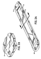
- Figure 2 provides a view of an electrodeionization spacer 16 that would receive a slurry brick.
- the brick would be inserted into the spacer channel 18, but only after a membrane 19 had been bonded to the spacer.
- the inset provides a view of the channel 22 in which the liquid traverses after passing through the media when the device is in operation.
- Figure 3 provides a sectional view of the device in Figure 2, wherein the spacer 16 has a membrane 19 between which is a cavity 20 in which resin is inserted. It further provides a retainer cap 24 that provides thin channels 26 that prevent the resin from entering the flow channel 22 of Figure 3.
- Figure 4 provides a view of a vibration table 28 on which a resin tray 10 may be vibrated so as to distribute evenly the ion exchange media.
- the tray 10 is fitted onto the table 28 such that the edge of the tray contacts the rubber vacuum seal 34. This is important as the vacuum needed to aspirate the excess water from the resin tray 10 is piped into the table 28.
- the vacuum is provided via a vacuum channel 30 on the upper table portion 29 of the table 28.
- a vacuum port 32 is fluidly connected to a vacuum connection 36. This design of the table allows simultaneous aspiration of the water while the tray, and hence the media, is vibrated.
- the upper table portion 29 is fixed to a lower table portion 35.
- Figure 5 provides a view of the support structure and the mechanism for vibrating the table 28.
- a vibrating cylinder 38 is fixed to the underside of the lower table portion 35 and the vibration forces it provides are transferred through the table 28 to the media.
- the vibrating cylinder was purchased from Branford Vibrator Company, located in Connecticut, USA.
- the movement created by the vibrational forces is controlled, but not suppressed, by fixing the lower table portion 35 to ball bushings 42 that are slidingly fixed to shaft rails 44.
- Such shaft rails 44 are supported by shaft support blocks 40.
- the ball bushings 42 move along the shaft rail 42 and thereby prevent side to side movement of the table 28. Rubber springs 46 and stop collars 48 restrict, but do not eliminate, the movement of the table along the plane of the shaft rails 44.
- Figure 6 provides a mold 10 with grooves 11 on the bottom of the mold 10 to facilitate ejection of the slurry brick from the mold 10.
Landscapes
- Chemical & Material Sciences (AREA)
- Engineering & Computer Science (AREA)
- Water Supply & Treatment (AREA)
- Chemical Kinetics & Catalysis (AREA)
- Health & Medical Sciences (AREA)
- Urology & Nephrology (AREA)
- Organic Chemistry (AREA)
- Water Treatment By Electricity Or Magnetism (AREA)
- Separation Using Semi-Permeable Membranes (AREA)
- Treatment Of Water By Ion Exchange (AREA)
- Manufacture Of Macromolecular Shaped Articles (AREA)
Claims (10)
- Procédé pour préparer une substance échangeuse d'ions pour utilisation dans la fabrication d'un dispositif d'électrodésionisation, comprenant les phases consistant à :préparer un moule d'une forme prédéterminée qui est sensiblement équivalente à celle d'un compartiment du dispositif d'électrodésionisation conçu pour recevoir la substance ;produire une bouillie à partir d'une matière particulaire échangeuse d'ions souhaitée et d'un liquide et transférer cette bouillie dans ledit moule ou produire ladite bouillie dans le moule ;congeler ladite bouillie jusqu'à ce qu'une brique solide soit créée ;extraire ladite brique solide du moule.
- Procédé selon la revendication 1, dans lequel ladite substance particulaire échangeuse d'ions comprend une résine échangeuse d'ions ou un mélange de résines échangeuses d'ions.
- Procédé selon la revendication 1, dans lequel ladite substance particulaire échangeuse d'ions comprend des perles de charbon actif.
- Procédé selon l'une quelconque des revendications 1 à 3, dans lequel ledit liquide est de l'eau.
- Procédé selon l'une quelconque des revendications 1 à 4, comprenant également la phase de distribution de la bouillie reçue dans le moule avant congélation.
- Procédé selon la revendication 5, dans lequel ladite bouillie reçue dans le moule est soumise à des vibrations pour être distribuée.
- Procédé selon la revendication 6, dans lequel ladite bouillie reçue dans le moule est soumise à des vibrations en faisant vibrer le moule.
- Procédé selon la revendication 6 ou 7, dans lequel ladite bouillie est soumise à des vibrations pendant 0,01 à 20 minutes, de préférence pendant environ 0,05 à 0,3 minute, de préférence pendant environ 0,08 minute.
- Procédé pour remplir d'une résine échangeuse d'ions un compartiment d'un écarteur utilisé dans un dispositif d'électrodésionisation comprenant les phases consistant à :préparer une brique solide congelée à partir de ladite résine échangeuse d'ions sensiblement équivalente en forme audit compartiment de l'écarteur d'après le procédé selon l'une quelconque des revendications 1 à 8, ettransférer ladite brique solide congelée dans ledit compartiment.
- Procédé pour préparer une substance échangeuse d'ions pour utilisation dans la fabrication d'un dispositif d'électrodésionisation, comprenant les phases consistant à :produire une bouillie à partir d'une substance particulaire échangeuse d'ions souhaitée et d'un liquide ;recevoir ladite bouillie dans une extrudeuse adaptée à extruder ladite bouillie en une forme prédéterminée qui est sensiblement équivalente à celle d'un compartiment du dispositif d'électrodésionisation conçu pour recevoir la substance ;congeler ladite bouillie tandis qu'elle est extrudée pour créer une brique solide.
Applications Claiming Priority (3)
| Application Number | Priority Date | Filing Date | Title |
|---|---|---|---|
| US6143897P | 1997-10-09 | 1997-10-09 | |
| US61438P | 1997-10-09 | ||
| PCT/US1998/021211 WO1999019053A1 (fr) | 1997-10-09 | 1998-10-08 | Procedes et dispositifs de production de sous-ensembles solides de matiere particulaire fluide |
Publications (2)
| Publication Number | Publication Date |
|---|---|
| EP1024885A1 EP1024885A1 (fr) | 2000-08-09 |
| EP1024885B1 true EP1024885B1 (fr) | 2002-12-18 |
Family
ID=22035773
Family Applications (1)
| Application Number | Title | Priority Date | Filing Date |
|---|---|---|---|
| EP98953315A Expired - Lifetime EP1024885B1 (fr) | 1997-10-09 | 1998-10-08 | Procedes de production de sous-ensembles solides de materiau particulaire fluide echangeur d'ions |
Country Status (6)
| Country | Link |
|---|---|
| US (2) | US6490777B1 (fr) |
| EP (1) | EP1024885B1 (fr) |
| JP (1) | JP3467015B2 (fr) |
| DE (1) | DE69810339T2 (fr) |
| ES (1) | ES2186236T3 (fr) |
| WO (1) | WO1999019053A1 (fr) |
Families Citing this family (10)
| Publication number | Priority date | Publication date | Assignee | Title |
|---|---|---|---|---|
| US20050267354A1 (en) * | 2003-02-04 | 2005-12-01 | Joel Marquart | System and method for providing computer assistance with spinal fixation procedures |
| US7840256B2 (en) * | 2005-06-27 | 2010-11-23 | Biomet Manufacturing Corporation | Image guided tracking array and method |
| US8571637B2 (en) | 2008-01-21 | 2013-10-29 | Biomet Manufacturing, Llc | Patella tracking method and apparatus for use in surgical navigation |
| JP5548016B2 (ja) * | 2010-04-19 | 2014-07-16 | オルガノ株式会社 | 乾燥カチオン交換樹脂の製造方法およびその製造方法で製造された乾燥カチオン交換樹脂 |
| US8834663B2 (en) | 2011-06-10 | 2014-09-16 | Dow Global Technologies Llc | Electrodeionization device including ion exchange spacer and method of assembly |
| US8961770B2 (en) | 2011-10-27 | 2015-02-24 | Pentair Residential Filtration, Llc | Controller and method of operation of a capacitive deionization system |
| US8671985B2 (en) | 2011-10-27 | 2014-03-18 | Pentair Residential Filtration, Llc | Control valve assembly |
| US9695070B2 (en) | 2011-10-27 | 2017-07-04 | Pentair Residential Filtration, Llc | Regeneration of a capacitive deionization system |
| US9010361B2 (en) | 2011-10-27 | 2015-04-21 | Pentair Residential Filtration, Llc | Control valve assembly |
| US9637397B2 (en) | 2011-10-27 | 2017-05-02 | Pentair Residential Filtration, Llc | Ion removal using a capacitive deionization system |
Family Cites Families (19)
| Publication number | Priority date | Publication date | Assignee | Title |
|---|---|---|---|---|
| US2536274A (en) * | 1947-01-22 | 1951-01-02 | Gen Motors Corp | Desiccant cartridge and method of making |
| US2815320A (en) * | 1953-10-23 | 1957-12-03 | Kollsman Paul | Method of and apparatus for treating ionic fluids by dialysis |
| GB942762A (en) | 1960-05-13 | 1963-11-27 | John Thompson Kennicott Ltd | A method of packing a receptacle with comminuted material |
| US3621086A (en) * | 1968-12-09 | 1971-11-16 | Crowe Gulde Cement Co | Method for making facing brick with varied color and texture |
| US4585583A (en) * | 1982-05-24 | 1986-04-29 | The Dow Chemical Company | In situ solidification of ion exchange beads |
| US4747929A (en) * | 1986-10-01 | 1988-05-31 | Millipore Corporation | Depletion compartment and spacer construction for electrodeionization apparatus |
| US4804550A (en) * | 1986-12-10 | 1989-02-14 | Tetley Inc. | Method for packaging ground coffee |
| JPS63247004A (ja) * | 1987-04-02 | 1988-10-13 | 株式会社神戸製鋼所 | シ−ト状セラミツクス成形体の製造方法 |
| US5024764A (en) * | 1989-03-17 | 1991-06-18 | Ametek, Inc. | Method of making a composite filter |
| US5120416A (en) * | 1990-03-19 | 1992-06-09 | Ionics, Incorporated | Introducing and removing ion-exchange and other particulates from an assembled electrodeionization stack |
| US5072770A (en) | 1990-06-22 | 1991-12-17 | Yodice Daniel B | Investment casting process |
| JPH05228913A (ja) * | 1991-07-26 | 1993-09-07 | Sumitomo Electric Ind Ltd | セラミックスの成形法および装置 |
| GB9413408D0 (en) * | 1994-07-04 | 1994-08-24 | British Petroleum Co | Process |
| JPH09155838A (ja) | 1995-12-07 | 1997-06-17 | Ngk Insulators Ltd | セラミックスの凍結成形法 |
| US5593563A (en) * | 1996-04-26 | 1997-01-14 | Millipore Corporation | Electrodeionization process for purifying a liquid |
| US5681438A (en) * | 1996-05-31 | 1997-10-28 | Millipore Corporation | Membrane module assembly |
| JP3330032B2 (ja) | 1996-10-25 | 2002-09-30 | 本田技研工業株式会社 | エアバッグ装置 |
| JPH11319498A (ja) * | 1998-05-13 | 1999-11-24 | Japan Organo Co Ltd | イオン交換樹脂の充填方法 |
| US6197174B1 (en) * | 1998-11-25 | 2001-03-06 | E-Cell Corporation | Method and apparatus for electrodeionization of water using mixed bed and single phase ion exchange materials in the diluting compartment |
-
1998
- 1998-10-08 EP EP98953315A patent/EP1024885B1/fr not_active Expired - Lifetime
- 1998-10-08 WO PCT/US1998/021211 patent/WO1999019053A1/fr not_active Ceased
- 1998-10-08 US US09/508,412 patent/US6490777B1/en not_active Expired - Lifetime
- 1998-10-08 ES ES98953315T patent/ES2186236T3/es not_active Expired - Lifetime
- 1998-10-08 DE DE69810339T patent/DE69810339T2/de not_active Expired - Lifetime
- 1998-10-08 JP JP2000515678A patent/JP3467015B2/ja not_active Expired - Lifetime
-
2002
- 2002-01-16 US US09/990,944 patent/US6625863B2/en not_active Expired - Lifetime
Also Published As
| Publication number | Publication date |
|---|---|
| ES2186236T3 (es) | 2003-05-01 |
| DE69810339D1 (de) | 2003-01-30 |
| DE69810339T2 (de) | 2003-10-16 |
| JP3467015B2 (ja) | 2003-11-17 |
| JP2001519231A (ja) | 2001-10-23 |
| WO1999019053A1 (fr) | 1999-04-22 |
| US6625863B2 (en) | 2003-09-30 |
| US6490777B1 (en) | 2002-12-10 |
| EP1024885A1 (fr) | 2000-08-09 |
| US20020066171A1 (en) | 2002-06-06 |
Similar Documents
| Publication | Publication Date | Title |
|---|---|---|
| US6625863B2 (en) | Methods for producing solid subassemblies of fluidic particulate matter | |
| EP0874689B1 (fr) | Appareil d'electrodesionisation avec disposition geometrique du materiau echangeur d'ions | |
| EP1474236B1 (fr) | Dispositifs a colonnes de separation microfluidique, et procedes de fabrication | |
| US4025425A (en) | Purification apparatus | |
| EP0810024B1 (fr) | Ensemble de module à membrane | |
| US6294090B1 (en) | Adsorptive substance separation device | |
| US6193869B1 (en) | Modular apparatus for the demineralization of liquids | |
| CN1263545C (zh) | 在稀释室中采用混合床和单相离子交换材料进行水电去离子化的方法及其装置 | |
| KR100947416B1 (ko) | 이온 흡착 모듈 및 수 처리 방법 | |
| EP2659951A1 (fr) | Module de membrane d'adsorption/de séparation, son procédé de production, et élément de partition | |
| CA2752453C (fr) | Dispositif de chromatographie | |
| EP1429861B1 (fr) | Module de filtration | |
| US20060118471A1 (en) | Stackable chromatography module, and chromatography column comprising a stack of said modules | |
| US6660160B1 (en) | Apparatus for separation of solids from a liquid | |
| JP4107750B2 (ja) | 脱塩室構造体及び電気式脱イオン液製造装置 | |
| CN104394965A (zh) | 灌封方法 | |
| CN100548449C (zh) | 离子交换介质的制备方法 | |
| IL33211A (en) | A method of producing membrane packs suitable for electrodialysis | |
| US12409440B1 (en) | Separation module | |
| JPH11319498A (ja) | イオン交換樹脂の充填方法 | |
| RU2156156C1 (ru) | Мембранный модуль для разделения жидких сред и способ его изготовления | |
| GB2377990A (en) | Multiwell plate | |
| HK1017292B (en) | Electrodeionization apparatus having geometric arrangement of ion exchange material | |
| MXPA98005620A (en) | Electrodesioning device that has a settlement or assembly of io exchange material | |
| JPS6084116A (ja) | システム濾過設備 |
Legal Events
| Date | Code | Title | Description |
|---|---|---|---|
| PUAI | Public reference made under article 153(3) epc to a published international application that has entered the european phase |
Free format text: ORIGINAL CODE: 0009012 |
|
| 17P | Request for examination filed |
Effective date: 20000425 |
|
| AK | Designated contracting states |
Kind code of ref document: A1 Designated state(s): DE ES FR GB IT |
|
| 17Q | First examination report despatched |
Effective date: 20010607 |
|
| RTI1 | Title (correction) |
Free format text: METHODS FOR PRODUCING SOLID SUBASSEMBLIES OF FLUIDIC PARTICULATE ION EXCHANGE MATERIAL |
|
| GRAG | Despatch of communication of intention to grant |
Free format text: ORIGINAL CODE: EPIDOS AGRA |
|
| RTI1 | Title (correction) |
Free format text: METHODS FOR PRODUCING SOLID SUBASSEMBLIES OF FLUIDIC PARTICULATE ION EXCHANGE MATERIAL |
|
| GRAG | Despatch of communication of intention to grant |
Free format text: ORIGINAL CODE: EPIDOS AGRA |
|
| GRAH | Despatch of communication of intention to grant a patent |
Free format text: ORIGINAL CODE: EPIDOS IGRA |
|
| GRAH | Despatch of communication of intention to grant a patent |
Free format text: ORIGINAL CODE: EPIDOS IGRA |
|
| GRAA | (expected) grant |
Free format text: ORIGINAL CODE: 0009210 |
|
| AK | Designated contracting states |
Kind code of ref document: B1 Designated state(s): DE ES FR GB IT |
|
| REG | Reference to a national code |
Ref country code: GB Ref legal event code: FG4D |
|
| REF | Corresponds to: |
Ref document number: 69810339 Country of ref document: DE Date of ref document: 20030130 Kind code of ref document: P Ref document number: 69810339 Country of ref document: DE Date of ref document: 20030130 |
|
| REG | Reference to a national code |
Ref country code: ES Ref legal event code: FG2A Ref document number: 2186236 Country of ref document: ES Kind code of ref document: T3 |
|
| RAP2 | Party data changed (patent owner data changed or rights of a patent transferred) |
Owner name: MILLIPORE CORPORATION |
|
| ET | Fr: translation filed | ||
| PLBE | No opposition filed within time limit |
Free format text: ORIGINAL CODE: 0009261 |
|
| STAA | Information on the status of an ep patent application or granted ep patent |
Free format text: STATUS: NO OPPOSITION FILED WITHIN TIME LIMIT |
|
| 26N | No opposition filed |
Effective date: 20030919 |
|
| REG | Reference to a national code |
Ref country code: ES Ref legal event code: PC2A Owner name: EMD MILLIPORE CORPORATION Effective date: 20120416 |
|
| REG | Reference to a national code |
Ref country code: FR Ref legal event code: CD Owner name: EMD MILLIPORE CORPORATION Effective date: 20120327 |
|
| REG | Reference to a national code |
Ref country code: DE Ref legal event code: R082 Ref document number: 69810339 Country of ref document: DE Representative=s name: HENKEL, BREUER & PARTNER, DE |
|
| REG | Reference to a national code |
Ref country code: DE Ref legal event code: R082 Ref document number: 69810339 Country of ref document: DE Representative=s name: PATENTANWAELTE HENKEL, BREUER & PARTNER, DE Effective date: 20120613 Ref country code: DE Ref legal event code: R081 Ref document number: 69810339 Country of ref document: DE Owner name: EMD MILLIPORE CORPORATION, BILLERICA, US Free format text: FORMER OWNER: MILLIPORE CORP., BEDFORD, MASS., US Effective date: 20120613 |
|
| REG | Reference to a national code |
Ref country code: FR Ref legal event code: PLFP Year of fee payment: 19 |
|
| REG | Reference to a national code |
Ref country code: FR Ref legal event code: PLFP Year of fee payment: 20 |
|
| PGFP | Annual fee paid to national office [announced via postgrant information from national office to epo] |
Ref country code: FR Payment date: 20170918 Year of fee payment: 20 |
|
| PGFP | Annual fee paid to national office [announced via postgrant information from national office to epo] |
Ref country code: DE Payment date: 20171004 Year of fee payment: 20 |
|
| PGFP | Annual fee paid to national office [announced via postgrant information from national office to epo] |
Ref country code: IT Payment date: 20171024 Year of fee payment: 20 Ref country code: ES Payment date: 20171106 Year of fee payment: 20 Ref country code: GB Payment date: 20171004 Year of fee payment: 20 |
|
| REG | Reference to a national code |
Ref country code: DE Ref legal event code: R071 Ref document number: 69810339 Country of ref document: DE |
|
| REG | Reference to a national code |
Ref country code: GB Ref legal event code: PE20 Expiry date: 20181007 |
|
| PG25 | Lapsed in a contracting state [announced via postgrant information from national office to epo] |
Ref country code: GB Free format text: LAPSE BECAUSE OF EXPIRATION OF PROTECTION Effective date: 20181007 |
|
| REG | Reference to a national code |
Ref country code: ES Ref legal event code: FD2A Effective date: 20200723 |
|
| PG25 | Lapsed in a contracting state [announced via postgrant information from national office to epo] |
Ref country code: ES Free format text: LAPSE BECAUSE OF EXPIRATION OF PROTECTION Effective date: 20181009 |