EP1024947B1 - Guide de bande de roulement de pneu a vis a billes - Google Patents
Guide de bande de roulement de pneu a vis a billes Download PDFInfo
- Publication number
- EP1024947B1 EP1024947B1 EP97936165A EP97936165A EP1024947B1 EP 1024947 B1 EP1024947 B1 EP 1024947B1 EP 97936165 A EP97936165 A EP 97936165A EP 97936165 A EP97936165 A EP 97936165A EP 1024947 B1 EP1024947 B1 EP 1024947B1
- Authority
- EP
- European Patent Office
- Prior art keywords
- ball screw
- tread
- guides
- conveyor
- accordance
- Prior art date
- Legal status (The legal status is an assumption and is not a legal conclusion. Google has not performed a legal analysis and makes no representation as to the accuracy of the status listed.)
- Expired - Lifetime
Links
- 230000000712 assembly Effects 0.000 description 7
- 238000000429 assembly Methods 0.000 description 7
- 238000000034 method Methods 0.000 description 2
- 230000008878 coupling Effects 0.000 description 1
- 238000010168 coupling process Methods 0.000 description 1
- 238000005859 coupling reaction Methods 0.000 description 1
- 230000003247 decreasing effect Effects 0.000 description 1
- 230000001419 dependent effect Effects 0.000 description 1
- 230000013011 mating Effects 0.000 description 1
Images

Classifications
-
- B—PERFORMING OPERATIONS; TRANSPORTING
- B29—WORKING OF PLASTICS; WORKING OF SUBSTANCES IN A PLASTIC STATE IN GENERAL
- B29D—PRODUCING PARTICULAR ARTICLES FROM PLASTICS OR FROM SUBSTANCES IN A PLASTIC STATE
- B29D30/00—Producing pneumatic or solid tyres or parts thereof
- B29D30/06—Pneumatic tyres or parts thereof (e.g. produced by casting, moulding, compression moulding, injection moulding, centrifugal casting)
- B29D30/38—Textile inserts, e.g. cord or canvas layers, for tyres; Treatment of inserts prior to building the tyre
- B29D30/44—Stretching or treating the layers before application on the drum
-
- B—PERFORMING OPERATIONS; TRANSPORTING
- B29—WORKING OF PLASTICS; WORKING OF SUBSTANCES IN A PLASTIC STATE IN GENERAL
- B29L—INDEXING SCHEME ASSOCIATED WITH SUBCLASS B29C, RELATING TO PARTICULAR ARTICLES
- B29L2030/00—Pneumatic or solid tyres or parts thereof
- B29L2030/002—Treads
Definitions
- This invention relates to an apparatus for applying a constant centering force on the edges of tire tread rubber as it travels across an application conveyor to a tire drum. Conicity offset adjustment is also provided by adjusting the position of the center line of the tread relative to the center line of the tire building drum.
- Apparatus for applying a uniform force perpendicular to the axis of the tread as it travels across an application conveyor toward a tire building drum is shown and described in US-A- 5,389,187.
- the method of applying the force is shown and described in US-A- 5,534,093.
- the tread is conveyed on a conveyor between two self-centering guides which are slidably mounted on a frame positioned over the conveyor.
- the guides have parallel rows of rollers for engaging opposite edges of the tread and are urged toward the tread edges by a pneumatic, double-acting piston cylinder assembly connected to the guides by pulleys and cables.
- the piston cylinder assembly is connected to a centering screw for adjusting the position of the tread centerline.
- US-A- 3,413,174 is directed to a conveyor apparatus having guide rolls for adjusting the longitudinal center line of the tread, however, no provision is made for accommodating a variable width of the tread.
- US-A-4,261,786 is directed to a conveyor apparatus having a pair of threaded shafts to rotate in threaded shoulder guides urging them towards the center of a tread with a motor rotating the shafts, however, there is no disclosure of a single ball screw extending between supporting frame members for moving two tire tread guides together and providing a continuous constant force against each side of a tire tread.
- the present invention is directed to apparatus for applying a constant centering force on the edges of tread rubber as it is carried by an application conveyor toward a tire building drum.
- the constant centering force is provided by a ball screw and nut assembly, with the ball screw torque controlled by a pneumatic rotary actuator connected to the screw.
- An adjustment sleeve provides conicity offset adjustment by moving the entire ball screw and nut assembly laterally along the axis of the ball screw whereby the position of the center line of the tread may be adjusted slightly relative to the center line of the tire building drum.
- apparatus for conveying a tire tread comprising a conveyor with two guides extending over the conveyor and having rollers engageable with side edges of the tread, characterized by the guides having nut members engageable with a ball screw extending between supporting frame members for moving the guides together or apart by rotating the ball screw and torque applying means including a pneumatic rotary actuator connected to the ball screw for applying torque to the ball screw to urge a nut member of a first one of the guides toward a first edge of the tread and a nut member of a second one of the guides toward a second edge of the tread and the torque applying means including a pneumatic rotary actuator connected to the ball screw providing a continuous constant force at each side of the tire tread by the rollers while in contact with the tread regardless of the variation in width of the tread, a clutch mounted between the ball screw and the pneumatic rotary actuator at a first end of the ball screw and manual means to rotate the screw mounted at a second end of the screw whereby the initial spacing of the guides may be provided by manually rotating
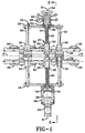
- a tread application conveyor 10 having rollers 12 for supporting a tread 14 as it travels over the conveyor towards a tire building drum (not shown).
- a frame 16 having side members 18 and a top member 20, is mounted on the conveyor 10 and positioned over the conveyor.
- two guides such as long rod assemblies 24 and 26 with ball bearing rollers 28 are suspended in housings 30 and 32 positioned above either side of the tread 14. The angular orientation of the rod assemblies 26 may be adjusted to place the rollers 28 in optimum locations to engage the shoulders of the tread 14.
- the housings 30 and 32 have bushings 34 and 36 slidably mounted on linear ways or rods 38 and 40 clamped to the side members 18 of carrier frame 16.
- a ball screw assembly 42 is positioned between the rods 38 and 40 generally at the center of the tread guiding apparatus.
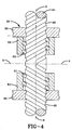
- a ball screw 44 shown more clearly in Fig. 4, is divided at its center line A-A into right-hand threads 46 at one side, and left-hand threads 48 at the other side.
- a left-hand ball screw nut 50 having a ball 51 is attached to the left-hand housing 30.
- a right-hand ball screw nut 52 having a ball 53 is attached to the right-hand housing 32. Accordingly, when the ball screw 44 is rotated the relative distance between the housings 30 and 32 will be increased or decreased.
- a hand wheel 54 is mounted at one end of the ball screw 44 and a torque applying means, such as a pneumatic rotary actuator 56, is mounted at the other end of the screw 44.
- a clutch 58 is positioned between the ball screw 44 and the pneumatic rotary actuator 56.
- a screw support bearing 60 is positioned inside a conicity adjustment sleeve 62 having external threads in mating engagement with threads on a mounting bracket 64, which is attached to one of the side members 18 of the frame 16.
- a lock nut 66 may be provided to hold the adjustment sleeve 62 in place.
- the lock nut 66 may be loosened and the conicity adjustment sleeve 62 rotated in the desired direction. This adjustment is used to move the center line of the tread 14 slightly from the center line of the tire building drum to improve conicity readings and is referred to as the "conicity offset adjustment.”
- a housing 68 holding the rotary actuator 56 and surrounding the clutch 58 is slidably mounted on shoulder screws 70, threaded in the other one of the side members 18 of the frame 16, permitting the housing to move relative to the frame during the conicity offset adjustment.
- the ball screw 44 provides width adjustment and centering for the self-centering rod assemblies 24 and 26. Adjustment of the distance between the rod assemblies 24 and 26 is provided by disengaging the clutch 58 and rotating the ball screw with the hand wheel 54 until the rod assemblies 24 and 26 reach the desired spacing. Preferably this is a setting which spaces the rollers 28 at a distance slightly narrower than the width of tread 14. The clutch 58 may then be engaged, coupling the ball screw 44 to the rotary actuator 56 to drive the rod assemblies 24 and 26 towards the center line A-A and providing centering of the rod assemblies 24 and 26.
- the tread guide of this invention utilizes the ball screw 44 to hold the housings 30 and 32 in a position with torque applied to the end of the ball screw by the pneumatic rotary actuator 56.
- This torque provides resistance to rotation of the ball screw 44 as the edges of the tread 44 press against the rollers 28 in a direction to open the space between the rollers.
- the torque provided may be changed by changing the air pressure in the pneumatic rotary actuator 56.
- the shaft of the pneumatic rotary actuator 56 may be positioned at one limit of its 280 degree travel, placing the housings 30 and 32 and rollers 28 at a spaced distance apart slightly less than the width of the tread. When the tread 14 reaches the rollers 28 and the edges make contact with the rollers, the rollers will be forced to open slightly.
Landscapes
- Engineering & Computer Science (AREA)
- Textile Engineering (AREA)
- Mechanical Engineering (AREA)
- Tyre Moulding (AREA)
Abstract
Claims (8)
- Appareil pour transporter une bande de roulement de bandage pneumatique (14) comprenant un transporteur (10) muni de deux guides (24, 26) s'étendant par-dessus ledit transporteur (10) et comportant des rouleaux (28) aptes à entrer en contact avec les bords latéraux opposés de ladite bande de roulement (14), lesdits guides (24, 26) possédant des éléments en forme d'écrous (50, 52) dans lesquels viennent s'insérer des vis à billes s'étendant entre des éléments de bâti de support (18) pour déplacer lesdits guides (24, 26) de manière conjointe ou de manière séparée en faisant tourner lesdites vis à billes, et un moyen d'application de couple relié auxdites vis à billes pour appliquer un couple sur lesdites vis à billes afin de presser un élément en forme d'écrou (50) du premier desdits guides en direction d'un premier bord de ladite bande de roulement (14) et un élément en forme d'écrou (52) du second desdits guides (24) en direction d'un second bord de ladite bande de roulement (14), caractérisé en ce que le moyen d'application de couple englobe un actionneur rotatif pneumatique (56) relié à une vis unique à billes (44) procurant une force constante continue contre chaque côté de ladite bande de roulement (14) via lesdits rouleaux (28) au cours de la mise en contact avec ladite bande de roulement (14) sans prendre en compte la variation de largeur de ladite bande de roulement de bandage pneumatique, un embrayage (58) monté entre ladite vis unique à billes (44) et ledit actionneur rotatif pneumatique (56) à une première extrémité de ladite vis unique à billes (44) et un moyen manuel (62) pour faire tourner ladite vis unique à billes (44) monté à une deuxième extrémité de ladite vis unique à billes (44), par lequel l'écartement initial desdits guides (24, 26) peut être fourni en faisant tourner à la main ladite vis unique à billes (44), et par lequel les forces de couple peuvent être appliquées en actionnant ledit embrayage (58) pour mettre en prise ledit actionneur rotatif pneumatique (56).
- Appareil selon la revendication 1, dans lequel ladite vis à billes (44) possède un grand pas, par lequel le mouvement linéaire desdits éléments en forme d'écrous (50, 52) est soumis à une translation pour obtenir un mouvement rotatif grâce au rendement mécanique de la combinaison de ladite vis (44) et desdits éléments en forme d'écrous (50, 52).
- Appareil selon la revendication 1, caractérisé en outre par un moyen de réglage de la conicité (62) pour déplacer ladite vis à billes (44) avec lesdits guides (24, 26) latéralement le long de l'axe B-B de ladite vis à billes (44) afin de régler la position de la ligne médiane A-A de la bande de roulement (14) sur ledit transporteur (16).
- Appareil selon la revendication 1, caractérisé en outre par le fait que ledit moyen de réglage de la conicité (62) comprend un manchon de réglage (62) en contact par filet de vis avec un palier de support de vis (60) dans un desdits éléments de bâti (16).
- Appareil selon la revendication 1, caractérisé en outre par le fait que chacun desdits guides (24, 26) possède une tige (38, 40), plusieurs rouleaux (28, 30) montés sur ladite tige (38, 40) à des fins de rotation en contact avec un bord incliné de ladite bande de roulement de bandage pneumatique (14), ainsi qu'un moyen pour incliner l'axe de rotation desdits rouleaux (38, 40) à des fins de correspondance avec les bords inclinée de ladite bande de roulement de bandage pneumatique (14).
- Appareil selon la revendication 1, caractérisé en outre par le fait que lesdits guides (24, 26) sont supportés en glissement sur des tiges (38, 40) montées sur ledit élément de bâti (16, 18) parallèlement à et à l'écart de ladite vis à billes (44), si bien qu'essentiellement tout le poids desdits guides (24, 26) est supporté par lesdites tiges.
- Appareil selon la revendication 1, caractérisé en outre par un moyen de réglage de la conicité (62) pour déplacer ladite vis à billes (44) avec lesdits guides (24, 26) latéralement le long de l'axe B-B de ladite vis à billes (44) afin de régler la position de la ligne médiane A-A de la bande de roulement (14) sur ledit transporteur (10).
- Appareil selon la revendication 1, caractérisé en outre par le fait que ledit moyen de réglage de la conicité comprend un manchon de réglage (62) en contact par filet de vis avec un palier de support de vis (60) dans un desdits éléments de bâti (16, 18).
Applications Claiming Priority (1)
| Application Number | Priority Date | Filing Date | Title |
|---|---|---|---|
| PCT/US1997/012870 WO1999006205A1 (fr) | 1997-08-04 | 1997-08-04 | Guide de bande de roulement de pneu a vis a billes |
Publications (2)
| Publication Number | Publication Date |
|---|---|
| EP1024947A1 EP1024947A1 (fr) | 2000-08-09 |
| EP1024947B1 true EP1024947B1 (fr) | 2001-11-28 |
Family
ID=22261318
Family Applications (1)
| Application Number | Title | Priority Date | Filing Date |
|---|---|---|---|
| EP97936165A Expired - Lifetime EP1024947B1 (fr) | 1997-08-04 | 1997-08-04 | Guide de bande de roulement de pneu a vis a billes |
Country Status (5)
| Country | Link |
|---|---|
| EP (1) | EP1024947B1 (fr) |
| AU (1) | AU3890097A (fr) |
| CA (1) | CA2297918A1 (fr) |
| DE (1) | DE69708704T2 (fr) |
| WO (1) | WO1999006205A1 (fr) |
Families Citing this family (1)
| Publication number | Priority date | Publication date | Assignee | Title |
|---|---|---|---|---|
| CN116080118B (zh) * | 2023-01-08 | 2024-11-22 | 青岛工学院 | 一种动力钢珠模组 |
Family Cites Families (6)
| Publication number | Priority date | Publication date | Assignee | Title |
|---|---|---|---|---|
| US3413174A (en) * | 1965-03-15 | 1968-11-26 | Goodrich Co B F | Conveyor apparatus |
| DE2318743B2 (de) * | 1973-04-13 | 1975-06-12 | Continental Gummi-Werke Ag, 3000 Hannover | Vorrichtung zum Berichtigen der Länge vulkanisierbarer Rohlaufstreifen |
| US3949920A (en) * | 1974-08-01 | 1976-04-13 | Uniroyal Inc. | Fabric alignment apparatus |
| US4261786A (en) * | 1978-10-27 | 1981-04-14 | Nrm Corporation | Modular servicer |
| JPH06155193A (ja) * | 1992-11-13 | 1994-06-03 | Nippon Chemicon Corp | 軸受ブッシュ圧入装置 |
| US5389187A (en) * | 1993-06-30 | 1995-02-14 | The Goodyear Tire & Rubber Company | Apparatus for tire tread application |
-
1997
- 1997-08-04 CA CA002297918A patent/CA2297918A1/fr not_active Abandoned
- 1997-08-04 DE DE69708704T patent/DE69708704T2/de not_active Expired - Fee Related
- 1997-08-04 WO PCT/US1997/012870 patent/WO1999006205A1/fr not_active Ceased
- 1997-08-04 EP EP97936165A patent/EP1024947B1/fr not_active Expired - Lifetime
- 1997-08-04 AU AU38900/97A patent/AU3890097A/en not_active Abandoned
Also Published As
| Publication number | Publication date |
|---|---|
| DE69708704D1 (de) | 2002-01-10 |
| AU3890097A (en) | 1999-02-22 |
| CA2297918A1 (fr) | 1999-02-11 |
| EP1024947A1 (fr) | 2000-08-09 |
| DE69708704T2 (de) | 2002-08-01 |
| WO1999006205A1 (fr) | 1999-02-11 |
Similar Documents
| Publication | Publication Date | Title |
|---|---|---|
| KR940009913B1 (ko) | 전송 롤 시스템 | |
| EP0634267B1 (fr) | Procédé et dispositif d'application d'une bande de roulement pour pneu | |
| JPH11257444A (ja) | テンション装置 | |
| EP1024947B1 (fr) | Guide de bande de roulement de pneu a vis a billes | |
| US6355136B1 (en) | Ball screw tire tread guide | |
| CN108557524B (zh) | 一种封面机用面纸输送、定位、对中调整装置 | |
| CN113601042A (zh) | 一种激光切管机用四爪卡盘 | |
| CN221313365U (zh) | 一种切管机固定夹持装置 | |
| EP1060112B1 (fr) | Transporteur a guides, comportant a son extremite un rouleau de renvoi reglable lateralement | |
| US5558202A (en) | Apparatus for moving circular container ends | |
| EP0253067B1 (fr) | Dispositif automatique de jonction transversale pour l'assemblage de pneus | |
| CN216227595U (zh) | 激光切管机用四爪卡盘 | |
| CN215047379U (zh) | 铝带传送装置 | |
| CN113607432B (zh) | 一种回转体测试装置 | |
| CN213536216U (zh) | 转运带用张紧结构 | |
| CN223804572U (zh) | 一种药用pvc硬片输送设备 | |
| CN220437092U (zh) | 一种网带驱动装置 | |
| CN223251771U (zh) | 一种纸板分切机 | |
| CN219278529U (zh) | 一种可自动纠偏的履带输送装置 | |
| CN111099253A (zh) | 输送机构 | |
| JP2001509463A (ja) | リード・フレームのための運搬装置と運搬アセンブリ | |
| CN223316087U (zh) | 一种纠偏装置及箔材卷绕设备 | |
| CA2426060A1 (fr) | Appareil de mesure de la geometrie de suspensions de vehicules a moteur | |
| CN115027065B (zh) | 一种绳锯机胶条压装工具 | |
| CN222372349U (zh) | 一种用于静音海绵轮胎加工的保压机构 |
Legal Events
| Date | Code | Title | Description |
|---|---|---|---|
| PUAI | Public reference made under article 153(3) epc to a published international application that has entered the european phase |
Free format text: ORIGINAL CODE: 0009012 |
|
| 17P | Request for examination filed |
Effective date: 20000306 |
|
| AK | Designated contracting states |
Kind code of ref document: A1 Designated state(s): DE FR GB IT |
|
| 17Q | First examination report despatched |
Effective date: 20001019 |
|
| GRAG | Despatch of communication of intention to grant |
Free format text: ORIGINAL CODE: EPIDOS AGRA |
|
| GRAG | Despatch of communication of intention to grant |
Free format text: ORIGINAL CODE: EPIDOS AGRA |
|
| GRAH | Despatch of communication of intention to grant a patent |
Free format text: ORIGINAL CODE: EPIDOS IGRA |
|
| GRAH | Despatch of communication of intention to grant a patent |
Free format text: ORIGINAL CODE: EPIDOS IGRA |
|
| GRAA | (expected) grant |
Free format text: ORIGINAL CODE: 0009210 |
|
| AK | Designated contracting states |
Kind code of ref document: B1 Designated state(s): DE FR GB IT |
|
| REG | Reference to a national code |
Ref country code: GB Ref legal event code: IF02 |
|
| REF | Corresponds to: |
Ref document number: 69708704 Country of ref document: DE Date of ref document: 20020110 |
|
| ET | Fr: translation filed | ||
| PG25 | Lapsed in a contracting state [announced via postgrant information from national office to epo] |
Ref country code: GB Free format text: LAPSE BECAUSE OF NON-PAYMENT OF DUE FEES Effective date: 20020804 |
|
| PLBE | No opposition filed within time limit |
Free format text: ORIGINAL CODE: 0009261 |
|
| STAA | Information on the status of an ep patent application or granted ep patent |
Free format text: STATUS: NO OPPOSITION FILED WITHIN TIME LIMIT |
|
| 26N | No opposition filed | ||
| PG25 | Lapsed in a contracting state [announced via postgrant information from national office to epo] |
Ref country code: DE Free format text: LAPSE BECAUSE OF NON-PAYMENT OF DUE FEES Effective date: 20030301 |
|
| GBPC | Gb: european patent ceased through non-payment of renewal fee |
Effective date: 20020804 |
|
| PG25 | Lapsed in a contracting state [announced via postgrant information from national office to epo] |
Ref country code: FR Free format text: LAPSE BECAUSE OF NON-PAYMENT OF DUE FEES Effective date: 20030430 |
|
| REG | Reference to a national code |
Ref country code: FR Ref legal event code: ST |
|
| PG25 | Lapsed in a contracting state [announced via postgrant information from national office to epo] |
Ref country code: IT Free format text: LAPSE BECAUSE OF NON-PAYMENT OF DUE FEES Effective date: 20050804 |