EP1025439B1 - Membranbasierte elektrochemische testvorrichtung und zugehörige verfahren - Google Patents
Membranbasierte elektrochemische testvorrichtung und zugehörige verfahren Download PDFInfo
- Publication number
- EP1025439B1 EP1025439B1 EP98949677A EP98949677A EP1025439B1 EP 1025439 B1 EP1025439 B1 EP 1025439B1 EP 98949677 A EP98949677 A EP 98949677A EP 98949677 A EP98949677 A EP 98949677A EP 1025439 B1 EP1025439 B1 EP 1025439B1
- Authority
- EP
- European Patent Office
- Prior art keywords
- electrode
- membrane
- test device
- analyte
- skin
- Prior art date
- Legal status (The legal status is an assumption and is not a legal conclusion. Google has not performed a legal analysis and makes no representation as to the accuracy of the status listed.)
- Expired - Lifetime
Links
Images



Classifications
-
- C—CHEMISTRY; METALLURGY
- C12—BIOCHEMISTRY; BEER; SPIRITS; WINE; VINEGAR; MICROBIOLOGY; ENZYMOLOGY; MUTATION OR GENETIC ENGINEERING
- C12Q—MEASURING OR TESTING PROCESSES INVOLVING ENZYMES, NUCLEIC ACIDS OR MICROORGANISMS; COMPOSITIONS OR TEST PAPERS THEREFOR; PROCESSES OF PREPARING SUCH COMPOSITIONS; CONDITION-RESPONSIVE CONTROL IN MICROBIOLOGICAL OR ENZYMOLOGICAL PROCESSES
- C12Q1/00—Measuring or testing processes involving enzymes, nucleic acids or microorganisms; Compositions therefor; Processes of preparing such compositions
- C12Q1/26—Measuring or testing processes involving enzymes, nucleic acids or microorganisms; Compositions therefor; Processes of preparing such compositions involving oxidoreductase
-
- C—CHEMISTRY; METALLURGY
- C12—BIOCHEMISTRY; BEER; SPIRITS; WINE; VINEGAR; MICROBIOLOGY; ENZYMOLOGY; MUTATION OR GENETIC ENGINEERING
- C12Q—MEASURING OR TESTING PROCESSES INVOLVING ENZYMES, NUCLEIC ACIDS OR MICROORGANISMS; COMPOSITIONS OR TEST PAPERS THEREFOR; PROCESSES OF PREPARING SUCH COMPOSITIONS; CONDITION-RESPONSIVE CONTROL IN MICROBIOLOGICAL OR ENZYMOLOGICAL PROCESSES
- C12Q1/00—Measuring or testing processes involving enzymes, nucleic acids or microorganisms; Compositions therefor; Processes of preparing such compositions
- C12Q1/001—Enzyme electrodes
Definitions
- the present invention relates to an electrochemical test device suitable for determining the presence or concentration of chemical and biochemical components (analytes) in aqueous fluid samples and body fluids such as whole blood or interstitial fluid. Additionally, this invention relates to a method of using such test devices for determining the presence or concentration of an analyte and to processes for preparing such a test devices.
- Such blood testing devices typically employ either a dry chemistry reagent system or an electrochemical method to test for the analyte in the fluid sample.
- electrochemical testing systems have become increasingly popular due to their small size and ease of use.
- electrochemical testing systems typically use electrochemistry to create an electrical signal which correlates to the concentration of the analyte in the aqueous sample.
- European Patent Publication No. 0 351 891 B1 to Hill et al., teaches a method of making an electrochemical sensor by printing.
- the sensor is used to detect, measure or monitor a given dissolved substrate in a mixture of dissolved substrates, most specifically glucose in body fluid.
- U.S. Patent No. 5,391,250 to Cheney II et al., teaches a method of fabricating thin film electrochemical sensors for use in measuring subcutaneous or transdermal glucose. Fabrication of the sensors comprises placing a thin film base layer of insulating material onto a rigid substrate. Conductor elements for the sensors are formed on the base layer using contact mask photolithography and a thin film cover layer.
- PATENT ABSTRACTS OF JAPAN vol. 9, no. 243 describes an electrochemical test device for measuring the concentration of glucose, wherein electrodes are provided on a base plate and films consisting of a semiconductive high polymer are formed on the bottom ends thereof.
- the device is constituted of a non-woven fabrics provided with a reactive member having glucose oxidase, peroxidase and iodide so as to contact with said films.
- electrochemical testing systems have certain limitations from the perspective of the end user or the manufacturer. For example, some electrochemical testing systems are difficult or costly to manufacture. As a result, such devices are too expensive to be used on a daily basis by, for example, diabetics. Other electrochemical testing systems are not sufficiently accurate to detect certain analytes at very low concentrations or to give reliable measurements of the analyte's concentration. Additionally, many electrochemical devices are too large to be easily carried by those needing to test their blood on a regular basis throughout the day. Thus, a need exists for improved electrochemical test devices.
- the present invention utilizes amorphous semiconductor applied with thin film manufacturing techniques and membranes which have a skin on each planar surface to provide an electrochemical test device suitable for determining the presence or concentration of analytes in aqueous fluid samples.
- amorphous semiconductor materials applied with film manufacturing techniques and dual skin membranes uniform electrochemical test devices having well-defined reproducible electrode areas can be manufactured economically.
- test devices of this invention have very uniform surface areas which reduce the variability of the electrochemical test.
- the surface area of the electrodes and the accuracy of applying the reagent are critical to producing an accurate test. If the surface area is not consistent from test to test then each of the test devices must be individually calibrated to insure accurate readings.
- the test devices of the present invention permit highly accurate electrochemical analyte measurements to be performed on very small aqueous fluid samples without the need for individual calibration of each test device.
- the present inventions provide for the accurate reproduction of the test devices by using controlled deposition methods, such as sputtering or vapor deposition and smooth skin membranes to form the electrodes with consistent size and surface morphology from device to device in continuous production.
- the membrane in the present invention is the carrier for the indicating reagent and forms the surface for the electrode formation.
- the membrane comprises the matrix in which the reagent is carried or impregnated and comprises the two exterior skin surfaces on which the electrodes are placed.
- the skin surfaces can be smooth skin suitable for carrying the electrodes and can be porous to pass the aqueous fluid samples or can have pores sized to screen or block selected components from aqueous fluid sample, such as red blood cells in a blood sample.
- Dry electrochemical test devices fall into two primary configurations.
- the first configuration utilizes two electrodes, i.e., a working electrode and a counter electrode.
- the second configuration utilizes three electrodes, i.e., a working electrode, a counter electrode and a reference electrode.
- the use of the reference electrode and a reference material provides a fixed reference for the test.
- the test devices of the present invention are well suited for a two electrode system however, a contact mask could be employed during sputtering to create a surface with two electrodes.
- the present invention provides an electrochemical test device for determining the presence or concentration of an analyte in an aqueous fluid sample, said electrochemical test device comprising:
- the test device further comprises a reference electrode comprising an amorphous semiconductor material affixed to the non-conductive surface, said reference electrode having an electrode area, a lead, and a contact pad, and wherein at least a portion of the electrode area is overlaid with a reference material.
- the reference material is a silver/silver chloride layer, a mercury/mercury chloride layer or a platinum/hydrogen material. This electrode could be either the counter electrode or an independent third electrode.
- the test device further comprises a blood separating membrane with two skin surfaces.
- the blood separating membrane separates whole blood samples into highly colored and relatively clear fluid portions before analysis.
- the blood separating membrane effectively blocks or filters red blood cells and allows essentially clear fluid to pass to the test reagent imbibed in the membrane matrix.
- the analyte is measured in the clear fluid portion of the sample contacting the electrodes thereby substantially eliminating the red blood cells from the reaction and minimizing interference from the cells present in blood.
- This embodiment has the additional benefit of keeping the test site from drying out and thereby improves the performance of test devices designed for small sample sizes, such as in the 1 to 5 microliter range.
- the membrane is selected from polysulphone, polyethersulphone, or nylon and is cased with a tight pore skin on each side and a relatively isotropic matrix between each skin surface
- the skin pore size is relatively tight approximately 0.1 to 0.5 microns in size and the isotropic matrix being 0.5 microns or greater in pore size.
- the tight pore size provides a uniform surface morphology on which the amorphous semiconductor electrodes are formed according to this invention. Better surface morphology of the membrane results in a more consistent surface for the amorphous semiconductor electrodes. This provides improved accuracy of test results and consistency of performance.
- the amorphous semiconductor material used in this invention is amorphous silicon oxide. More preferably, the amorphous silicon oxide is doped with lithium, potassium, or a similar conducting ion to increased conductivity. Doping with lithium is particularly preferred. However, amorphous carbon, gold, silver or other conductor materials which do not interfere with the electrochemistry of the reagent system are also suitable.
- the amorphous semiconductor material can be applied by using various techniques including sputtering, evaporation, vapor phase deposition or other thin film deposition technique to form a conductive layer on the membrane surface
- the surface texture of the amorphous semiconductor material is preferably less than 13 micro inches or 0.33 microns. However, rougher textures can be used depending on the accuracy of the desired test device.
- the reagent employed in the electrochemical test device is typically selected based on the analyte to be tested and the desired detection limits.
- the reagent preferably comprises an enzyme and a redox mediator.
- the enzyme is preferably glucose oxidase and the redox mediator is potassium ferrocyanide.
- the electrochemical test device of the present invention is used to determine the presence or concentration of an analyte in an aqueous fluid sample. Accordingly, in one of its method aspects, the present invention provides a method for determining the presence or concentration of an analyte in an aqueous fluid sample, said method comprising:
- the test device employed in this method further comprises a reference electrode comprising an amorphous semiconductor material affixed to the counter electrode membrane surface, said reference electrode having a third electrode area, a third lead, and a third contact pad, and wherein at least a portion of the third electrode area is overlaid with a reference material.
- the reference material is a silver/silver chloride layer, a mercury/mercury chloride layer or a platinum/hydrogen material.
- Silver/silver chloride is a particularly preferred reference material.
- the separation of the counter electrode conductive path and reference electrode is accomplished by using a mask to create the different geometries on the same surface.
- the membrane is selected from polysulphone, polyethersulphone, or nylon and is cased with a tight pore skin on each side and a relatively isotropic matrix between each skin surface
- the skin pore size is relatively tight approximately 0.1 to 0.5 microns in size and the isotropic matrix being 0.5 microns or greater in pore size.
- the tight pore size provides a uniform surface morphology on which the amorphous semiconductor electrodes are formed according to this invention. Better surface morphology of the membrane results in a more consistent surface for the amorphous semiconductor electrodes. This provides improved accuracy of test results and consistency of performance.
- the present invention utilizes amorphous semiconductor materials and thin manufacturing techniques to provide electrochemical test devices.
- Thin film technologies can be used to create the amorphous semiconductor material conductive layers and electrodes according to this invention. Accordingly, in one of its process aspects, the present invention provides a process for preparing an electrochemical test device suitable for determining the presence or concentration of an analyte in an aqueous fluid sample, said process comprising the steps of:
- step (c) of this process further comprises forming a reference electrode comprising a third electrode having a third electrode area, a third lead and a third contact pad. This is accomplished by using a mask to form the two distinct electrodes and in a step (e) forming a silver chloride surface.
- step (a) above comprises the steps of:
- step (d) above comprises the steps of:
- step (d) above further comprises the steps of:
- the process employed to prepare the test devices of this invention is a continuous process.
- the present invention utilizes amorphous semiconductor materials and double skin membranes to provide an electrochemical test device suitable for determining the presence or concentration of analytes in aqueous fluid samples.
- amorphous semiconductors and the double skinned membranes uniform electrochemical test devices having well-defined reproducible electrode areas can be manufactured economically. These areas have very uniform surface morphology which reduces the variability of the electrochemical test.
- the surface morphology is directly related to the surface area of the electrodes.
- the amount and concentration of applied reagents are also critical to producing an accurate test. If the surface area is not consistent from device to device then the individual devices manufactured have to be individually calibrated to insure accurate readings in a meter.
- test devices of the present invention permit highly accurate electrochemical analyte measurements to be performed on very small aqueous fluid samples due to the accurate reproduction of the test devices using controlled deposition methods such as sputtering, vapor phase deposition, glow discharge methods or evaporation and the very uniform surface of the double skin membranes to form the geometries.
- controlled deposition methods such as sputtering, vapor phase deposition, glow discharge methods or evaporation and the very uniform surface of the double skin membranes to form the geometries.
- These devices can also be readily manufactured due to the lower cost and flexible nature of the amorphous semiconductor materials which allow the use of volume production in continuous processing manufacturing methods.
- Thin film technologies are preferred for forming the amorphous semiconductor material layer or coating, such as sputtering, vapor phase deposition, glow discharge methods or evaporation. Such processes are capable of producing coatings up to a thickness of a few microns and of applying the coatings uniformly over the entire surface. If desired, thick film technologies are capable of producing much thicker layers in the range of less than 0.005 inches. While both methods can produce uniform surfaces, thin film surface morphology is dependent on the surface roughness of the underlying substrate, whereas the thick film technologies are capable of changing the final surface morphology of the device due to their thicker structure.
- the electrochemical test device of this invention employs at least two types of electrodes.
- the first type of electrode is referred to as the "working or indicating electrode” and the second type is referred to as the "counter or opposing electrode".
- These electrodes permit changes in potential between the electrodes to be accurately measured when the analyte is applied across the electrodes, and the reagent reactive with the analyte is bound to the membrane matrix between the electrodes formed on the skin.
- the test device may also contain a reference electrode.
- the reference electrode allows accurate measurements of potential to be made with respect to a fixed reference point. Any suitable reference electrode may be used, include silver/silver chloride, mercury/mercury chloride and platinum/hydrogen reference electrodes.
- the reference electrode is a silver/silver chloride reference electrode and the working electrode has a potential ranging from about +1 to -1 volts versus the reference electrode.
- Reference electrodes suitable for use in this invention are further described in R. S. C. Cobbold, Transducers for Biomedical Measurements: Principles and Applications , pp. 343-349, John Wiley & Sons (New York).
- the electrodes in the test device of this invention are manufactured using a double skinned membrane.
- Any suitable dielectric material may be used as the material for the membrane matrix as long as a tight pore skin can be formed on both sides of the membrane.
- polysulphone, polyethersulphone, or nylon is casted with a tight pore skin on each side and a relatively isotropic matrix between each skin surface.
- the skin pore size is relatively tight approximately 0.1 to 0.5 microns in size and the isotropic matrix being 0.5 microns or greater in pore size.
- Such polymeric materials are well known in the art and are commercially available.
- the membranes employed in preferred embodiments of this invention is Supor 200 available from Pall Gelman Sciences
- the electrodes are then prepared on the membrane using semiconductor manufacturing techniques.
- a conductive layer is first deposited on or applied to the membrane.
- the conductive layer comprises an amorphous semiconductor material, such as amorphous silicon oxide, amorphous carbon, gold or silver and the like.
- Amorphous metals can be formed by permitting a small amount of helium gas to escape in the sputtering chamber during sputtering. Such materials are well known in the art. For example, formation of suitable amorphous semiconductor films are described in U.S. Patent No. 4,226,898, to Ovshinsky, the disclosure of which is incorporated herein by reference in its entirety.
- the amorphous semiconductor material employed in this invention is doped with lithium, potassium, or a similar conducting ion to increased conductivity.
- the amorphous semiconductor material is preferably deposited on the nonconducting membrane skin to form a conductive layer having a thickness of less than about 0.005 inches, more preferably a thickness ranging from about 1 to about 5 microns.
- the amorphous semiconductor material may be applied to the membrane using any art recognized procedure to form a conductive layer, such as sputtering, vapor phase deposition, glow discharge deposition, evaporation and the like. Alternatively, other deposition techniques such as electroplating, thick film laminating, roll transfer and the like may be employed.
- Thinner films are best achieved by sputtering, evaporation, vapor phase deposition, glow discharge methods or other thin film deposition method whereas thicker films are best formed using thick film deposition techniques such as electroplating, thick film laminating, roll transfer and the like.
- Charles A. Harper, Handbook of Materials and Processes for Electronics , 1984, (Library of Congress card number 76-95803) discusses various methods of forming thin films in Chapter 11, describes various thick film process in Chapter.
- the amorphous semiconductor material is deposited using vapor phase deposition or sputtering techniques.
- the amorphous semiconductor material is formed by co-deposition of the amorphous semiconductor material and the doping material such as by co-vacuum deposition or co-sputtering.
- Co-sputtering can be accomplished in a conventional DC or RF. sputtering system, such as available from ULVAC Vacuum Systems.
- a cathode or target is bonded to a standard aluminum backing plate and is made of the semiconductor material to be deposited.
- pieces of the doping material are secured to the cathode or target.
- Substrates upon which the amorphous semiconductor material and the doping material are to be deposited are carried by a holder located from the target by a distance of about 3.5 cm for a 3 1/3" diameter cathode or passed continuously by the target.
- the sputtering machine is first evacuated to a vacuum pressure somewhat less than about 6 ⁇ 10 -6 torr to provide a background vacuum pressure.
- Argon is bled into the machine to provide an operating pressure of about 5 ⁇ 10 -3 torr as determined by a reading on a Pirani vacuum gauge, giving an actual vacuum pressure of about 7 ⁇ 10 -3 torr in the machine.
- the surface of the cathode or target and pieces of doping material are first cleaned by sputtering against the shutter of the machine adjacent to substrates for about 30 minutes. Thereafter, the shutter is opened and the semiconductor material of the target and the pieces of doping material on the target are co-sputtered onto the non-conductive coating or substrate.
- the cathode or target and the holder for the substrates are both water cooled so that their temperature is low during the sputtering operation, as for example, approximately 50°C.
- the RF. power of the machine may have a frequency of about 13.56 MegaHertz, and about 1000 Volts of forward power, about 50-70 Watts being utilized for 3.5" diameter cathode or target.
- the deposition rates depend upon the materials being sputtered, and the time of deposition is varied to obtain desired thicknesses of the deposit.
- the thicknesses of the simultaneously deposited amorphous semiconductor film having the doping material therein may vary from a few hundred Angstroms to about 5 microns (5 ⁇ ), depending upon the uses to which the amorphous semiconductor film is to be put.
- the amorphous semiconductor material is deposited on the membrane.
- the amount of doping material homogeneously incorporated in the amorphous semiconductor material is generally determined by the area of the pieces of the doping material applied to the semiconductor material of the cathode or target. Desired percentage of modifier material added to the amorphous semiconductor material may accordingly be conveniently controlled.
- the doping material is substantially homogeneously incorporated in the semiconductor material to provide the beneficial features of this invention.
- the amorphous semiconductor material is applied continuously to the membrane using art recognized continuous processes.
- Such continuous processes are described, for example, in U.S. Patent No. 3,983,076, to Rockstad, and in U.S. Patent Nos. 3,271,591 and 4,178,415, to Ovshinsky, the disclosures of which are incorporated herein by reference in their entirety.
- the third electrode is constructed by using a contact mask which isolates the two electrodes formed on the bottom skin.
- the contact mask permits only application of sputtered material in the open areas and does not permit the coating on the covered areas.
- the reference electrode is then converted into a reference electrode by applying a suitable reference material.
- suitable reference materials include silver/silver chloride, a mercury/mercury chloride and platinum/hydrogen materials. Such materials can be applied to the third electrode area of the reference electrode by any thin film deposition method described above.
- a particularly preferred reference material is silver/silver chloride.
- the silver/silver chloride layer must be applied such that the silver/silver chloride layer covers essentially the same surface area in each device manufactured. Preferably, this is accomplished using contact mask as described above to expose a precise area of the electrode after developing.
- a thin layer of silver is then deposited on the exposed area, preferably by sputtering or other consistent film application method.
- the silver layer is preferably less than about 0.001 inches in thickness, more preferably about 1 micron to about 5 microns in thickness.
- a silver layer can be applied to the electrode area of the reference electrode using pad printing, inkjet methods, transfer roll printing or similar techniques. The silver layer is then contacted with FeCl 3 solution to convert the silver surface to silver chloride thereby forming a silver/silver chloride layer
- the electrochemical test device is then completed by applying an appropriate reagent to the membrane.
- the reagent is imbibed into the membrane matrix under the sample application area.
- Suitable reagents for determining the presence or concentration of various analytes are well known in the art and are described in further detail herein below.
- the electrodes for the electrochemical test device of this invention are prepared using amorphous semiconductor materials and double sided skinned membrane. Preferably, such electrodes are formed in a continuous manner.
- a preferred process for the preparation of electrodes suitable for use in this invention is illustrated in Figures 1-9.
- the membrane 1 which has skins 12 and 13 is coated with amorphous semiconductor material creating surfaces 2 and 4 which are the electrodes have a thickness of less than about 0.005 inches and preferable in the range of 1 to 5 microns.
- Figure 4 shows an isometric view of the top non conductive layer 4 which has been coated with adhesive 7.
- Non conductive layer 4 has holes 5 and 6 punched in the layer.
- Hole 5 is the sample application hole and permits the application of the indicating reagent during manufacture.
- Hole 6 is permits the measuring device to contact the conductive surface of the membrane.
- Figure 5 shows an isometric view of the membrane with conductive layers 2 and 4 and reference coating 14 (not shown) applied to the opposite side of the membrane.
- FIG. 6 shows an isometric view of the bottom non conductive layer 10 which has been coated with adhesive 8.
- Non conductive layer 10 has holes 9 and 11 punched in the layer.
- Hole 9 is the sample vent hole and permits the venting of the air in the membrane during application of the indicating reagent when the strip is manufactured.
- Hole 11 is permits the measuring device to contact the conductive surface of the membrane.
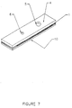
- Figure 7 is an isometric view of the finished device showing the membrane 1 sandwiched between the top and bottom non conductive layers 4 & 10 with top vent hole 5 and top contact hole 6.
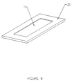
- FIG. 8 is a bottom view of a membrane showing opposing electrode 3 and reference electrode 15 with reference coating 14.
- the pattern is formed by sputtering on the skin and using a contact mask to pattern the electrodes.
- the membrane 1 can be loaded into a frame 20 to permit discrete manufacturing.
- reagents may be applied to the electrodes.
- a reagent chemistry must be selected based on the analyte to be tested and the desired detection limits.
- the reagent is deposited on the membrane such that a uniform amount is applied from sensor to sensor.
- the reagent may be applied using any conventional procedure, such as nozzle coating through the hole 5 in layer 4 using IVEK pumps or any other drop on demand system capable of delivering consistent and uniform volume of reagent.
- the reagent is applied through the working electrode, but may in some cases also be applied through the other electrodes. After the reagent has been imbibed into the membrane, it is typically dried. Subsequently, when the test device is used, the test sample. of aqueous fluid, such as blood, rehydrates the reagent and a potential is applied to the electrodes from which a current measurement may be taken by a meter.
- the membrane matrix acts as reagent carrier and electrode spacer. This permits the device to have a reduced manufacturing cost due to the excellent uniformity of the membrane thickness and isotropic nature of the inner matrix of the membrane.
- This reagent may be used to determine the presence or concentration of glucose in an aqueous fluid sample.
- this reagent formulation is used with an electrochemical sensor having an opposing electrode 3 , working electrode 2 and reference electrode 15 .
- the above reagent formulation may be prepared using the following procedures:
- the above reagent formulation may be used to determine the presence or concentration of glucose in an aqueous fluid sample.
- other reagent formulations may be employed to assay different analytes.
- Such reagent formulations are well known in the art.
- such reagent formulations are designed to react specifically with the desired analyte to form a measurable electrochemical signal.
- glucose is anaerobically oxidized or reduced with the involvement of the enzyme and the redox mediator.
- Such a system is sometimes referred to as an amperometric biosensor.
- Amperometry refers to a current measurement at constant applied voltage on the working electrode. In such a system, the current flowing is limited by mass transport. Therefore, the current is proportional to the bulk glucose concentration.
- the analyte, enzyme and mediator participate in a reaction where the mediator is either reduced (receives at least one electron) or oxidized (donates at least one electron). The glucose reaction ends when glucose oxidase is oxidized and the mediator is reduced.
- the mediator is then oxidized at the surface of the working electrode by the applied potential difference. Changes in the system amperage result from changes in the ratio of oxidized/reduced form of the redox mediator. The amperage change directly correlate to the detection or measurement of glucose in the test sample.
- enzymes may be used in the reagent formulations employed in this invention.
- the particular enzyme employed will vary depending on the analyte to be detected or measured.
- Preferred enzymes include glucose oxidase, glucose dehydrogenase, cholesterol esterase and alcohol oxidase.
- the amount of enzyme employed will generally range from about 0.5 to about 3.0 million units of enzyme per liter of reagent formulation.
- the reagent formulation will also typically contain a redox mediator.
- the redox mediator will generally be chosen to be compatible with the enzyme employed and combinations of redox mediators and enzymes are well known in the art. Suitable redox mediators include, by way of example, potassium ferricyanide and ferrocene derivatives, such as 1,1 ⁇ -dimethyl ferrocene.
- the amount of redox mediator employed in the reagent formulation will typically range from about 0.15 M to about 0.7 M.
- mediators suitable for use in this invention include methylene blue, p -benzoquinone, thionine, 2,6-dichloroindophenol, gallocyanine, indophenol, polyviologen, osmium bis(2,2 ⁇ -bipyridine) dihydrochloride, and riboflavin-5 ⁇ -phosphate ester.
- these mediators can be chemically bound or entrapped in a matrix, such as a polymer, using procedures well known in the art.
- enzyme/mediator combinations suitable for use in this invention include, but are not limited to, the following: Analyte Enzyme Mediator glucose glucose dehydrogenase ferricyanide glucose glucose oxidase tetracyanoquinodimethane cholesterol cholesterol esterase ferricyanide alcohol alcohol oxidase phenylenediamine
- a preferred reagent chemistry uses potassium ferricyanide as a mediator.
- the reagent layer on the electrode preferably further comprises a buffer, a stabilizer, a dispersant, a thickener or a surfactant.
- a buffer typically employed in amounts which optimize the reaction of the reagents with the analyte.
- concentration ranges for these components referred to below are for the reagent formulation before it has dried on the electrode surface.
- a buffer is preferably employed in the reagent formulation to provide a satisfactory pH for enzyme function.
- the buffer used must have a higher oxidation potential than the reduced form of the redox mediator.
- a preferred buffer for use in this invention is a phosphate buffer having a concentration ranging from about 0.1 M to about 0.5 M.
- Other suitable buffers include BES, BICINE, CAPS, EPPS, HEPES, MES, MOPS, PIPES, TAPS, TES and TRICINE buffers (collectively known as 'GOOD' buffers), citrate, TRIS buffer, and the like.
- the 'GOOD' and TRIS buffers are commercially available from Sigma-Aldrich, Inc. (St. Louis, MO, USA).
- a stabilizer may also be employed in the reagent formulation to stabilize the enzyme.
- a preferred stabilizer is potassium glutamate at a concentration ranging from about 0.01 to 4.0 % weight.
- Other suitable stabilizers include succinate, aspartate, blue dextran and the like.
- dispersants may be used in the reagent formulation to enhance the dispersion of the redox mediator and to inhibit its recrystallisation.
- Suitable dispersants include microcrystalline cellulose, dextran, chitin and the like.
- the dispersant is used in the reagent formulation in an amount ranging from about 1.0 to about 4.5 % weight.
- Preferred dispersants include, but are not limited to, AVICEL RC-591 (a microcrystalline cellulose available from FMC Corp.) and NATROSOL-250 M (a microcrystalline hydroxyethylcellulose available from Aqualon).
- a thickener may also be employed in the reagent formulation to hold the reagent to the electrode surface.
- Suitable thickeners include water soluble polymers, such as polyvinylpyrrolidone.
- a surfactant may be added to the reagent formulation to facilitate rapid and total wetting of the electrode surface.
- the reagent formulation contains a nonionic surfactant in an amount ranging from about 0.01 to 0.3 % by weight.
- a preferred surfactant is TRITON X-100, available from Sigma-Aldrich, Inc.
- glucose assay is described. It will be understood, however, that by selecting the proper reagent, other analytes may be determined using these procedures.
- the electrodes of the electrochemical test device are prepared as described above and the membrane is coated with 1.0 ⁇ L of the above-described reagent formulation and dried.
- the electrochemical test device is then inserted in a meter before the test sequence is initiated.
- Any suitable meter device which has contacts that interface with the test device contacts may be employed.
- Such metering devices are well known in the art.
- the meter will generally contain a measuring circuit and be adapted to apply an algorithm to the current measurement whereby the analyte level is provided and visually displayed. Examples of suitable power sources and meters may be found, for example, in U.S. Patent Nos. 4,963,814, 4,999,632, and 4,999,582 to Parks et al., U.S. Patent No. 5,243,516 to White et al., and European Patent Application No. 89116797.5, to Hill et al.
- a small sample of blood or other aqueous fluid is then applied to the test device.
- the current is measured about 10 to about 30 seconds after applying the sample.
- the current is read by the meter between the working and counter electrode and, optionally, is compared to the reference electrode, if it is present.
- the meter then applies the algorithm to the current measurement and converts the measurement to an analyte concentration. This analyte level is visually displayed on the meter.
Landscapes
- Chemical & Material Sciences (AREA)
- Organic Chemistry (AREA)
- Life Sciences & Earth Sciences (AREA)
- Zoology (AREA)
- Wood Science & Technology (AREA)
- Proteomics, Peptides & Aminoacids (AREA)
- Health & Medical Sciences (AREA)
- Engineering & Computer Science (AREA)
- Microbiology (AREA)
- Immunology (AREA)
- Physics & Mathematics (AREA)
- Molecular Biology (AREA)
- Biotechnology (AREA)
- Biophysics (AREA)
- Analytical Chemistry (AREA)
- Biochemistry (AREA)
- Bioinformatics & Cheminformatics (AREA)
- General Engineering & Computer Science (AREA)
- General Health & Medical Sciences (AREA)
- Genetics & Genomics (AREA)
- Investigating Or Analysing Biological Materials (AREA)
Claims (15)
- Elektrochemische Testvorrichtung zur Bestimmung der Gegenwart oder Konzentration eines Analyten in einer wäßrigen Flüssigkeitsprobe, wobei die elektrochemische Testvorrichtung aufweist:(a) eine nichtleitende Membran mit einer ersten Haut und einer zweiten Haut und einer dazwischen liegenden Matrix;(b) eine Arbeitselektrode, die ein an der ersten Haut der nichtleitenden Membran fixiertes amorphes Halbleitermaterial aufweist, wobei die Arbeitselektrode eine erste Elektrodenfläche, eine erste Zuleitung und eine erste Kontaktinsel aufweist;(c) eine Gegenelektrode, die ein an der zweiten Haut der nichtleitenden Membran fixiertes amorphes Halbleitermaterial aufweist, wobei die Gegenelektrode eine zweite Elektrodenfläche, eine zweite Zuleitung und eine zweite Kontaktinsel aufweist; und(d) ein Reagens, das mit dem Analyten reaktionsfähig ist, um eine meßbare Potentialänderung zu erzeugen, die in Beziehung zur Konzentration des Analyten in der Flüssigkeitsprobe gesetzt werden kann, wobei das Reagens in die Membran Matrix zwischen der Arbeitselektrode und der Gegenelektrode aufgenommen ist.
- Elektrochemische Testvorrichtung nach Anspruch 1, wobei die Vorrichtung ferner eine Bezugselektrode mit einem an der zweiten Haut der nichtleitenden Membran fixierten amorphen Halbleitermaterial aufweist, wobei die Bezugselektrode eine dritte Elektrodenfläche, eine dritte Zuleitung und eine dritte Kontaktinsel aufweist, und wobei mindestens ein Teil der dritten Elektrodenfläche mit einem Bezugsmaterial überschichtet ist.
- Elektrochemische Testvorrichtung nach Anspruch 2, wobei das Bezugsmaterial Silber/Silberchlorid ist.
- Elektrochemische Testvorrichtung nach Anspruch 1, wobei die nichtleitende Membran aus einem Material besteht, das unter Polysulfon, Polyethersulfon oder Nylon ausgewählt und auf jeder Seite mit einer engporigen Haut verkleidet ist und eine relativ isotrope Matrix zwischen den Hautoberflächen bildet.
- Elektrochemische Testvorrichtung nach Anspruch 1, wobei das amorphe Halbleitermaterial amorphes Siliciumdioxid ist.
- Elektrochemische Testvorrichtung nach Anspruch 1, wobei das Reagens eine Glucoseoxidase und einen Redoxvermittler aufweist.
- Verfahren zur Bestimmung der Gegenwart oder Konzentration eines Analyten in einer wäßrigen Flüssigkeitsprobe, wobei das Verfahren die folgenden Schritte aufweist:(a) Bereitstellen einer elektrochemischen Testvorrichtung, die aufweist: (i) eine nichtleitende doppelhäutige Membran; (ii) eine Arbeitselektrode, die ein an der ersten Hautoberfläche der nichtleitenden Membran fixiertes amorphes Halbleitermaterial aufweist, wobei die Arbeitselektrode eine erste Elektrodenfläche, eine erste Zuleitung und eine erste Kontaktinsel aufweist; (iii) eine Gegenelektrode, die ein an der zweiten Hautoberfläche der nichtleitenden Membran fixiertes amorphes Halbleitermaterial aufweist, wobei die Gegenelektrode eine zweite Elektrodenfläche, eine zweite Zuleitung und eine zweite Kontaktinsel aufweist; und (iv) ein Reagens, das mit dem Analyten reaktionsfähig ist, um eine meßbare Potentialänderung zu erzeugen, die in Beziehung zur Gegenwart oder Konzentration des Analyten in der Flüssigkeitsprobe gesetzt werden kann, wobei das Reagens in die Membran zwischen der Arbeitselektrode und der Gegenelektrode aufgenommen ist;(b) Einsetzen der elektrochemischen Testvorrichtung in ein Meßgerät;(c) Aufbringen einer Probe einer wäßrigen Flüssigkeit auf die erste Elektrodenfläche der Arbeitselektrode;(d) Ablesen des Meßgeräts, um die Gegenwart oder Konzentration des Analyten in der Flüssigkeitsprobe zu bestimmen.
- Verfahren nach Anspruch 7, wobei die elektrochemische Testvorrichtung ferner eine Bezugselektrode mit einem an der zweiten Hautoberfläche der nichtleitenden Membran fixierten amorphen Halbleitermaterial aufweist, wobei die Bezugselektrode eine dritte Elektrodenfläche, eine dritte Zuleitung und eine dritte Kontaktinsel aufweist, und wobei mindestens ein Teil der dritten Elektrodenfläche mit einem Bezugsmaterial überschichtet ist.
- Verfahren nach Anspruch 7, wobei die nichtleitende Membran aus einem Material besteht, das unter Polysulfon, Polyethersulfon oder Nylon ausgewählt und auf jeder Seite mit einer engporigen Haut verkleidet ist und eine relativ isotrope Matrix zwischen den Hautoberflächen bildet.
- Verfahren nach Anspruch 7, wobei das Reagens ein Enzym und einen Redoxvermittler aufweist.
- Verfahren zur Herstellung einer elektrochemischen Testvorrichtung zur Bestimmung der Gegenwart oder Konzentration eines Analyten in einer wäßrigen Flüssigkeitsprobe, wobei das Verfahren die folgenden Schritte aufweist:(a) Bereitstellen einer nichtleitenden doppelhäutigen Membran;(b) Aufbringen eines amorphen Halbleitermaterials auf die erste Hautoberfläche zur Ausbildung einer leitfähigen Schicht, die eine Arbeitselektrode bildet, die eine erste Elektrode mit einer ersten Elektrodenfläche, einer ersten Zuleitung und einer ersten Kontaktinsel aufweist;(c) Aufbringen eines amorphen Halbleitermaterials auf die zweite Hautoberfläche zur Ausbildung einer leitfähigen Schicht, die eine Gegenelektrode bildet, die eine zweite Elektrode mit einer zweiten Elektrodenfläche, einer zweiten Zuleitung und einer zweiten Kontaktinsel aufweist;(d) Aufbringen eines Reagens zum Aufnehmen der Membran durch die erste Elektrodenfläche der Arbeitselektrode hindurch, wobei das Reagens mit dem Analyten in einer wäßrigen Flüssigkeitsprobe reaktionsfähig ist, um eine meßbare Potentialänderung zu erzeugen, die in Beziehung zur Konzentration des Analyten in der Flüssigkeitsprobe gesetzt werden kann.
- Verfahren nach Anspruch 11, wobei der Schritt (c) ferner die Ausbildung einer Bezugselektrode auf der zweiten Hautoberfläche aufweist, die eine dritte Elektrode mit einer dritten Elektrodenfläche, einer dritten Zuleitung und einer dritten Kontaktinsel aufweist.
- Verfahren nach Anspruch 11, wobei die nichtleitende Membran aus einem Material besteht, das unter Polysulfon, Polyethersulfon oder Nylon ausgewählt und auf jeder Seite mit einer engporigen Haut verkleidet ist und eine relativ isotrope Matrix zwischen den Hautoberflächen bildet.
- Verfahren nach Anspruch 11, wobei das Reagens eine Glucoseoxidase und einen Redoxvermittler aufweist.
- Verfahren nach Anspruch 12, wobei das Verfahren kontinuierlich ist.
Applications Claiming Priority (3)
| Application Number | Priority Date | Filing Date | Title |
|---|---|---|---|
| US6048897P | 1997-09-30 | 1997-09-30 | |
| US60488 | 1997-09-30 | ||
| PCT/US1998/020575 WO1999017115A1 (en) | 1997-09-30 | 1998-09-30 | Membrane based electrochemical test device and related methods |
Publications (2)
| Publication Number | Publication Date |
|---|---|
| EP1025439A1 EP1025439A1 (de) | 2000-08-09 |
| EP1025439B1 true EP1025439B1 (de) | 2003-12-10 |
Family
ID=22029805
Family Applications (1)
| Application Number | Title | Priority Date | Filing Date |
|---|---|---|---|
| EP98949677A Expired - Lifetime EP1025439B1 (de) | 1997-09-30 | 1998-09-30 | Membranbasierte elektrochemische testvorrichtung und zugehörige verfahren |
Country Status (5)
| Country | Link |
|---|---|
| EP (1) | EP1025439B1 (de) |
| JP (1) | JP2001518620A (de) |
| AU (1) | AU9595298A (de) |
| DE (1) | DE69820471T2 (de) |
| WO (1) | WO1999017115A1 (de) |
Families Citing this family (15)
| Publication number | Priority date | Publication date | Assignee | Title |
|---|---|---|---|---|
| US7276146B2 (en) | 2001-11-16 | 2007-10-02 | Roche Diagnostics Operations, Inc. | Electrodes, methods, apparatuses comprising micro-electrode arrays |
| US6562210B1 (en) * | 1999-12-30 | 2003-05-13 | Roche Diagnostics Corporation | Cell for electrochemical anaylsis of a sample |
| ATE406571T1 (de) * | 2000-03-28 | 2008-09-15 | Diabetes Diagnostics Inc | Zeitmesser mit schnell ansprechenden glucose sensor |
| US6726818B2 (en) * | 2000-07-21 | 2004-04-27 | I-Sens, Inc. | Biosensors with porous chromatographic membranes |
| JP4517498B2 (ja) * | 2000-11-24 | 2010-08-04 | パナソニック株式会社 | バイオセンサ |
| JP4517527B2 (ja) * | 2001-03-29 | 2010-08-04 | パナソニック株式会社 | バイオセンサ |
| US20030116447A1 (en) | 2001-11-16 | 2003-06-26 | Surridge Nigel A. | Electrodes, methods, apparatuses comprising micro-electrode arrays |
| WO2003057905A1 (en) | 2001-12-28 | 2003-07-17 | Arkray, Inc. | Method of colorimetry and reagent for use therein |
| CA2494250C (en) * | 2002-08-13 | 2009-02-10 | Gunze Limited | Biosensor and method for manufacturing same |
| US9017544B2 (en) | 2002-10-04 | 2015-04-28 | Roche Diagnostics Operations, Inc. | Determining blood glucose in a small volume sample receiving cavity and in a short time period |
| IL153012A0 (en) * | 2002-11-21 | 2003-06-24 | Yissum Res Dev Co | Method and device for detecting analytes |
| US7563588B2 (en) | 2003-10-29 | 2009-07-21 | Agency For Science, Technology And Research | Electrically non-conductive, nanoparticulate membrane |
| JP5228891B2 (ja) * | 2008-11-21 | 2013-07-03 | 株式会社リコー | センサデバイス |
| ES2568464T3 (es) * | 2010-07-23 | 2016-04-29 | F. Hoffmann-La Roche Ag | Composiciones que contienen tampón zwiteriónico y usos en dispositivos y métodos electroanalíticos |
| CN109863396B (zh) * | 2016-10-05 | 2021-11-05 | 雅培实验室 | 用于样品分析的装置和方法 |
Family Cites Families (7)
| Publication number | Priority date | Publication date | Assignee | Title |
|---|---|---|---|---|
| CA1226036A (en) * | 1983-05-05 | 1987-08-25 | Irving J. Higgins | Analytical equipment and sensor electrodes therefor |
| JPS6095343A (ja) * | 1983-10-31 | 1985-05-28 | Toshiba Battery Co Ltd | グルコ−ス濃度測定方法およびその装置 |
| DE4014109A1 (de) * | 1990-05-02 | 1991-11-07 | Siemens Ag | Elekrochemische bestimmung der sauerstoffkonzentration |
| EP0592805A3 (en) * | 1992-09-09 | 1996-07-24 | Agency Ind Science Techn | Carbon sensor electrode and process for producing the same |
| DE4300499A1 (de) * | 1993-01-07 | 1994-07-14 | Klein Karl Dittmar Dr | Analytisches Verfahren für Elektrodensensoren |
| US5437999A (en) * | 1994-02-22 | 1995-08-01 | Boehringer Mannheim Corporation | Electrochemical sensor |
| JP3453954B2 (ja) * | 1994-11-02 | 2003-10-06 | トヨタ自動車株式会社 | 一酸化炭素検出装置、有機化合物検出装置および低級アルコール検出装置 |
-
1998
- 1998-09-30 JP JP2000514133A patent/JP2001518620A/ja active Pending
- 1998-09-30 EP EP98949677A patent/EP1025439B1/de not_active Expired - Lifetime
- 1998-09-30 WO PCT/US1998/020575 patent/WO1999017115A1/en not_active Ceased
- 1998-09-30 DE DE69820471T patent/DE69820471T2/de not_active Expired - Lifetime
- 1998-09-30 AU AU95952/98A patent/AU9595298A/en not_active Abandoned
Also Published As
| Publication number | Publication date |
|---|---|
| AU9595298A (en) | 1999-04-23 |
| DE69820471T2 (de) | 2004-06-09 |
| JP2001518620A (ja) | 2001-10-16 |
| DE69820471D1 (de) | 2004-01-22 |
| WO1999017115A1 (en) | 1999-04-08 |
| EP1025439A1 (de) | 2000-08-09 |
Similar Documents
| Publication | Publication Date | Title |
|---|---|---|
| US6245215B1 (en) | Membrane based electrochemical test device and related methods | |
| US7115362B2 (en) | Electrochemical test device and related methods | |
| EP1025439B1 (de) | Membranbasierte elektrochemische testvorrichtung und zugehörige verfahren | |
| US6805780B1 (en) | Electrochemical biosensor test strip, fabrication method thereof and electrochemical biosensor | |
| US5658443A (en) | Biosensor and method for producing the same | |
| EP1310787A1 (de) | Elektrochemische Zellen | |
| MX2007006127A (es) | Bionsensores que comprenden electrodos semiconductores o mediadores que contienen rutenio y metodo de uso de los mismos. | |
| CA2625833A1 (en) | Analyte sensor and method of making it | |
| BRPI0717430A2 (pt) | Sistema de biossensor tendo estabilidade e desempenho de hematócritos maiores | |
| CA2398203A1 (en) | Electrochemical methods and devices for use in the determination of hematocrit corrected analyte concentrations | |
| KR20020088521A (ko) | 시료도입의 능력을 향상시킨 크로마토그래피 기능의다공성 박막이 구비된 바이오센서 | |
| CN116818875A (zh) | 基于垂直石墨烯微电极阵列的电化学传感装置及制备方法 | |
| US11561220B2 (en) | Electrode for electrochemical sensors | |
| TWI765934B (zh) | 用於生物感測器的釕合金 | |
| Borchardt et al. | Disposable sodium electrodes | |
| US20150047976A1 (en) | Analytical test strip having cantilevered contacts | |
| TW201432258A (zh) | 具有可溶解之酸性材料塗層之基於電化學的分析測試條 | |
| GB2518165A (en) | Electrochemical-based analytical test strip with ultra-thin discontinuous metal layer | |
| ZA200107967B (en) | Electrochemical biosensor test strip, fabrication method thereof and electrochemical biosensor. | |
| HK1112964B (en) | Concentration determination in a diffusion barrier layer | |
| HK1057609B (en) | Electrochemical cells |
Legal Events
| Date | Code | Title | Description |
|---|---|---|---|
| PUAI | Public reference made under article 153(3) epc to a published international application that has entered the european phase |
Free format text: ORIGINAL CODE: 0009012 |
|
| 17P | Request for examination filed |
Effective date: 20000405 |
|
| AK | Designated contracting states |
Kind code of ref document: A1 Designated state(s): DE FR GB |
|
| RAP1 | Party data changed (applicant data changed or rights of an application transferred) |
Owner name: AMIRA MEDICAL |
|
| GRAH | Despatch of communication of intention to grant a patent |
Free format text: ORIGINAL CODE: EPIDOS IGRA |
|
| GRAS | Grant fee paid |
Free format text: ORIGINAL CODE: EPIDOSNIGR3 |
|
| GRAA | (expected) grant |
Free format text: ORIGINAL CODE: 0009210 |
|
| AK | Designated contracting states |
Kind code of ref document: B1 Designated state(s): DE FR GB |
|
| PG25 | Lapsed in a contracting state [announced via postgrant information from national office to epo] |
Ref country code: FR Free format text: LAPSE BECAUSE OF FAILURE TO SUBMIT A TRANSLATION OF THE DESCRIPTION OR TO PAY THE FEE WITHIN THE PRESCRIBED TIME-LIMIT Effective date: 20031210 |
|
| REG | Reference to a national code |
Ref country code: GB Ref legal event code: FG4D |
|
| REF | Corresponds to: |
Ref document number: 69820471 Country of ref document: DE Date of ref document: 20040122 Kind code of ref document: P |
|
| PG25 | Lapsed in a contracting state [announced via postgrant information from national office to epo] |
Ref country code: GB Free format text: LAPSE BECAUSE OF NON-PAYMENT OF DUE FEES Effective date: 20040930 |
|
| PLBE | No opposition filed within time limit |
Free format text: ORIGINAL CODE: 0009261 |
|
| STAA | Information on the status of an ep patent application or granted ep patent |
Free format text: STATUS: NO OPPOSITION FILED WITHIN TIME LIMIT |
|
| 26N | No opposition filed |
Effective date: 20040913 |
|
| EN | Fr: translation not filed | ||
| GBPC | Gb: european patent ceased through non-payment of renewal fee |
Effective date: 20040930 |
|
| PGFP | Annual fee paid to national office [announced via postgrant information from national office to epo] |
Ref country code: DE Payment date: 20100930 Year of fee payment: 13 |
|
| REG | Reference to a national code |
Ref country code: DE Ref legal event code: R081 Ref document number: 69820471 Country of ref document: DE Owner name: ROCHE DIAGNOSTICS GMBH, DE Free format text: FORMER OWNER: ROCHE DIAGNOSTICS OPERATIONS INC. (N.D.GES.D.STAATES DELAWARE), INDIANAPOLIS, IND., US Effective date: 20110516 Ref country code: DE Ref legal event code: R081 Ref document number: 69820471 Country of ref document: DE Owner name: ROCHE DIAGNOSTICS GMBH, DE Free format text: FORMER OWNER: ROCHE DIAGNOSTICS OPERATIONS INC. (N.D.GES.D.STAATES DELAWARE), INDIANAPOLIS, US Effective date: 20110516 |
|
| REG | Reference to a national code |
Ref country code: DE Ref legal event code: R119 Ref document number: 69820471 Country of ref document: DE Effective date: 20120403 |
|
| PG25 | Lapsed in a contracting state [announced via postgrant information from national office to epo] |
Ref country code: DE Free format text: LAPSE BECAUSE OF NON-PAYMENT OF DUE FEES Effective date: 20120403 |