EP1025810A2 - Form zum Einbetten von Modellen in eine Einbettmasse zur Erstellung von Gussformen für Dentalwerkstücke - Google Patents
Form zum Einbetten von Modellen in eine Einbettmasse zur Erstellung von Gussformen für Dentalwerkstücke Download PDFInfo
- Publication number
- EP1025810A2 EP1025810A2 EP99125062A EP99125062A EP1025810A2 EP 1025810 A2 EP1025810 A2 EP 1025810A2 EP 99125062 A EP99125062 A EP 99125062A EP 99125062 A EP99125062 A EP 99125062A EP 1025810 A2 EP1025810 A2 EP 1025810A2
- Authority
- EP
- European Patent Office
- Prior art keywords
- peripheral wall
- mold
- mold according
- bottom part
- transparent
- Prior art date
- Legal status (The legal status is an assumption and is not a legal conclusion. Google has not performed a legal analysis and makes no representation as to the accuracy of the status listed.)
- Granted
Links
- 239000000463 material Substances 0.000 title claims description 16
- 230000002093 peripheral effect Effects 0.000 claims abstract description 15
- 238000007789 sealing Methods 0.000 claims description 13
- 229920003023 plastic Polymers 0.000 claims description 8
- 238000005266 casting Methods 0.000 claims description 5
- 238000000465 moulding Methods 0.000 claims description 4
- 229920002457 flexible plastic Polymers 0.000 claims 1
- 239000002985 plastic film Substances 0.000 claims 1
- 230000007704 transition Effects 0.000 claims 1
- 150000001875 compounds Chemical class 0.000 abstract description 5
- 239000013013 elastic material Substances 0.000 abstract description 2
- 238000000034 method Methods 0.000 description 3
- 239000004033 plastic Substances 0.000 description 3
- 210000000332 tooth crown Anatomy 0.000 description 2
- 229920001875 Ebonite Polymers 0.000 description 1
- 239000004927 clay Substances 0.000 description 1
- 239000003086 colorant Substances 0.000 description 1
- 238000001816 cooling Methods 0.000 description 1
- 239000013078 crystal Substances 0.000 description 1
- 230000001419 dependent effect Effects 0.000 description 1
- 238000011161 development Methods 0.000 description 1
- 230000018109 developmental process Effects 0.000 description 1
- 239000011888 foil Substances 0.000 description 1
- 239000004973 liquid crystal related substance Substances 0.000 description 1
- 239000002184 metal Substances 0.000 description 1
- 238000012986 modification Methods 0.000 description 1
- 230000004048 modification Effects 0.000 description 1
- 239000007787 solid Substances 0.000 description 1
Images
Classifications
-
- A—HUMAN NECESSITIES
- A61—MEDICAL OR VETERINARY SCIENCE; HYGIENE
- A61C—DENTISTRY; APPARATUS OR METHODS FOR ORAL OR DENTAL HYGIENE
- A61C13/00—Dental prostheses; Making same
- A61C13/20—Methods or devices for soldering, casting, moulding or melting
-
- Y—GENERAL TAGGING OF NEW TECHNOLOGICAL DEVELOPMENTS; GENERAL TAGGING OF CROSS-SECTIONAL TECHNOLOGIES SPANNING OVER SEVERAL SECTIONS OF THE IPC; TECHNICAL SUBJECTS COVERED BY FORMER USPC CROSS-REFERENCE ART COLLECTIONS [XRACs] AND DIGESTS
- Y10—TECHNICAL SUBJECTS COVERED BY FORMER USPC
- Y10S—TECHNICAL SUBJECTS COVERED BY FORMER USPC CROSS-REFERENCE ART COLLECTIONS [XRACs] AND DIGESTS
- Y10S164/00—Metal founding
- Y10S164/04—Dental
Definitions
- the invention relates to a form according to the preamble of protection claim 1 or 3.
- dental workpieces are to be understood in particular as tooth crowns and dental bridges.
- An embedding mold for creating a casting mold for such dental workpieces is known (DE 85 19 112).
- the object of the invention is to show an embedding form that compared to this known embedding form while maintaining the accuracy with regard to the create Molds brings an improvement and simplification of handling.
- the wall of an open blank is one Foil made of a transparent, preferably crystal clear or essentially made of clear plastic, with this film overlapping its ends too the wall enclosing the molding space is rolled up, the Cohesion of the film ends and the support of the film by the outer Cuff is reached.
- the wall can pass through simply lift off the cuff and unwind the wall Cutting can be removed particularly easily and quickly.
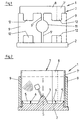
- the embedding mold 1 shown in FIGS. 1-4 consists inter alia of from a bottom part 2, which is made of hard rubber or another elastic material in the form of a circular disk is made.
- the bottom part 2 has one on the top rounded truncated cone-shaped projection 2, which is concentric to a symmetry or Center axis S of the base part 2 is formed.
- the bottom part 2 continues to have radially opposite the projection 3 offset to the outside an annular, the axis of symmetry S concentrically enclosing gradation 4.
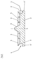
- the bottom part 2 is in one piece with a circumferential, the Axis of symmetry S concentrically enclosing sealing lip 5 is made in the representation chosen for Figure 3, i.e. from the other elements of the Embedding removed bottom part 2 protrudes over the surface 4 '.
- the Sealing lip 5 is multiple at 6 in the illustrated embodiment interrupted or incised.
- the embedding mold 1 also consists of a circular cylindrical wall 7, which in its attached to the bottom part 2, the axis of symmetry S also concentric encloses and from an open blank 7 'a transparent or translucent film is made of a plastic material, which only a certain strength or rigidity for the wall 7 is guaranteed.
- the cut 7 'to the wall 7 is such rolled up that the two ends of the blank overlap at 8 without that the blank ends are connected to each other, so that an enlargement of the Diameter of the interior of the embedding mold 1 is possible without the wall 7 such an increase in diameter with a substantial counterforce counteracts.
- the lower edge of the wall 7 stands on the surface 4 ′′ and lies in the Area of the lower edge with the inner surface against the surface 4 'and also against the sealing lip 5 so that a tight seal is achieved.
- the sealing lip 5 can change the inner diameter of the embedding mold follow practically without strength.
- the Wall 7 encloses and from at least part of the height of the embedding mold 1 is made of a harder plastic material.
- the cuff 9 is at 10 slotted continuously, so that the cuff 9 on the two through the slit 10 formed end 9 'resiliently bent or opened as far can that a placement and removal of the cuff 9 on or from the Wall 7 is possible.
- the cuff 9 holds the in its attached state Wall 7 together.
- the ends 9 ' each provided a recess 11 forming a grip surface. Furthermore, the Cuff 9 provided with various recesses or windows 12 through which when the mold 1 is assembled, the interior of the mold also from the side remains visible, namely through the film forming the wall 7 through it.
- the model 13 is a known Fixed tooth crown or a bridge, namely via a web-like element 14, which is also made from the modeling clay (wax) and later the Casting channel forms when casting the crown or bridge.
- the embedding mold is used in such a way that after assembly this form 1 and the arrangement of the respective model 13 in the interior of the Embedding the investment from the open top into the investment mold is introduced, this introduction not only from above, but also from the side can be observed through the window-shaped openings 11 and 12. In particular, it can also be observed or ensured that the investment material flows optimally into the cavity of the model 13 without any air pockets remain.
- the wall 7 is above the upper edge of the Cuff 9 in front. This also enables the filling state of the To control the investment form with the investment material, in particular also to prevent it, that too much investment is introduced into the investment mold 1 and thereby over the upper edge flows, which is an opening of the embedding mold after the curing Investments would at least complicate.
- the investment materials used are designed so that they Hardening, but especially if it is already hardening certain solid state is reached, so expand by increasing the of the respective model 13 in the molding compound molded by the Cooling caused the metal or cast crown or bridge to shrink compensate. Even small forces or constraints can cause this expansion process disrupt, for example in such a way that with a restriction or Constriction of the expansion process through the wall 7 of the expansion process takes place in the direction of the axis of symmetry S, thereby producing the crown or bridge then has too large dimensions in this axis direction, while in the perpendicular axis directions the dimensions below the desired value.
- Essential components of the embedding mold 1 are thus those from the blank 7 ' Transparent plastic manufactured cylindrical peripheral wall 7, this Circumferential wall-supporting sleeve 9, the bottom part 2 with the free-standing, however with 6 multi-cut sealing lip 5.
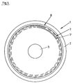
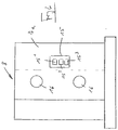
- Figures 5 and 6 show another possible embodiment in which the Wall 7a enclosing the molding space in turn is made of the translucent material is made, but the material is chosen so that the wall 7a already has the necessary strength.
- the wall 7a is again designed so that the relevant blank 7a 'overlaps so that when expanding the used Investment an increase in the inside diameter of the mold interior is possible without the wall 7a being gaped apart by the blank 7a ' is leaking.
- Through the free-standing, multiple-cut sealing lip 5 in this embodiment there are again these when expanding Embedding compound after, so that undesirable deformations in the shape and so that they are effectively avoided in the dental workpiece produced.
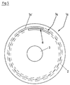
- FIG. 6 denotes a display which is provided on the blank 7a and which responds to the temperature of the investment compound when hardening.
- This display 15 is formed, for example, by a liquid crystal temperature display which, in the embodiment shown, has three fields 15 1 , 15 2 and 15 3 , which are each activated at different temperatures and then appear in different colors, for example field 15 1 in red a low temperature with the meaning that the embedding mold still has to be kept closed, the field 15 2 in yellow color a somewhat higher temperature with the meaning that the embedding mold should open as soon as possible and the field 15 3 in green color with the Meaning that the embedding mold should now be opened immediately.
- the display 15 prevents that by opening the embedding mold too early and thus an uncontrolled expansion of the investment takes place due to an early release, which leads to cracks in the investment material or in the produced mold.
- At 16 are in the figure 6 two Velcro closures with which the overlapping ends are connected to one another in the region of the overlap 8, without the desired flexibility of the wall 7a being lost.
Landscapes
- Health & Medical Sciences (AREA)
- Oral & Maxillofacial Surgery (AREA)
- Dentistry (AREA)
- Epidemiology (AREA)
- Life Sciences & Earth Sciences (AREA)
- Animal Behavior & Ethology (AREA)
- General Health & Medical Sciences (AREA)
- Public Health (AREA)
- Veterinary Medicine (AREA)
- Dental Prosthetics (AREA)
- Dental Preparations (AREA)
Abstract
Description
- Fig. 1
- in vereinfachter Darstellung und in Seitenansicht eine Einbettform gemäß der Erfindung;
- Fig. 2
- die Form der Figur 1 im Längsschnitt;
- Fig. 3
- das Bodenteil in Einzeldarstellung;
- Fig. 4
- eine Draufsicht auf das Bodenteil der Einbettform der Figuren 1 und 2;
- Fig. 5
- in einer Darstellung ähnlich Figur 4 eine weitere Ausführung der erfindungsgemäßen Form;
- Fig. 6
- die Ausführung der Figur 5 in vereinfachter Seitenansicht.
- 1, 1a
- Einbettform
- 2
- Bodenteil
- 3
- Vorsprung
- 4
- Abstufung
- 4', 4''
- Fläche
- 5
- Dichtungslippe
- 6
- Einschnitt
- 7, 7a
- Wandung
- 7', 7a'
- Zuschnitt aus durchsichtigem Kunststoff
- 8
- Überlappung
- 9
- Manschette
- 9'
- Ende
- 10
- Schlitz
- 11, 12
- Ausnehmung
- 13
- Modell
- 14
- stegartiger Abschnitt
- 15
- Temperaturanzeige
- 151,152,153
- Feld
- 16
- Klettverschluß
Claims (10)
- Form zum Einbetten von Modellen in einer Einbettmasse zur Erstellung von Gußformen für Dental-Werkstücke, wie Kronen, Brücken, mit einem zumindest ein Modell aufnehmenden und mit der Einbettmasse auffüllbaren Formraum, der von einer zylindrischen Umfangswand (7, 7a) sowie von einem Bodenteil (2) verschlossen ist, dadurch gekennzeichnet, daß die Umfangswand von einem Zuschnitt (7', 7a') eines transparenten bzw. durchsichtigen Kunststoff-Flachmaterial gebildet ist, und daß sich der Zuschnitt (7', 7a') an zwei Enden zur Bildung der geschlossenen Umfangswand überlappt, ohne daß die Enden miteinander verbunden sind.
- Form nach Anspruch 1, dadurch gekennzeichnet, daß das Bodenteil (2) eine Dichtungslippe (5) aufweist, die zur Abdichtung des Übergangs zwischen dem Bodenteil und der Umfangswandung (7) gegen die Innenfläche der Umfangswandung anliegt, und daß die Dichtungslippe (5) mehrfach geteilt bzw. eingeschnitten ist.
- Form zum Einbetten von Modellen in einer Einbettmasse zur Erstellung von Gußformen für Dental-Werkstücke, wie Kronen, Brücken, mit einem zumindest ein Modell (13) aufweisenden und mit der Einbettmasse auffüllbaren Formraum, der von einer zylindrischen Umfangswand (7, 7a) sowie von einem Bodenteil (2) verschlossen ist, wobei am Bodenteil eine von diesem Bodenteil wegstehende Dichtungslippe (5) vorgesehen ist, die zum Abdichten des Formraumes gegen die Innenfläche der Umfangswand (7, 7a) anliegt, dadurch gekennzeichnet, daß die Dichtungslippe (5) mehrfach eingeschnitten ist.
- Form nach Anspruch 3, dadurch gekennzeichnet, daß die Umfangswand (7, 7a) von einem Zuschnitt (7', 7a') aus einem transparenten bzw. durchsichtigen Kunststoff-Flachmaterial gebildet ist, welches sich an zwei Enden zur Bildung der geschlossenen Umfangswand überlappt, ohne daß diese Enden miteinander verbunden sind.
- Form nach einem der vorhergehenden Ansprüche, dadurch gekennzeichnet, daß die Umfangswand (7) von einem Zuschnitt (7') einer transparenten bzw. durchsichtigen Kunststoff-Folie gebildet ist, und daß zur Stützung der die Umfangswand (7) bildenden Folie außen eine die Umfangswand umgebene Manschette (9) vorgesehen ist, die beispielsweise aus einem elastischen oder flexiblem Kunststoff besteht.
- Form nach einem der vorhergehenden Ansprüche, dadurch gekennzeichnet, daß die Manschette (9) aus transparentem oder lichtdurchlässigem Material hergestellt ist und/oder Sichtfenster bildende Öffnungen oder Ausnehmungen (11, 12) aufweist.
- Form nach einem der vorhergehenden Ansprüche, dadurch gekennzeichnet, daß die Manschette (9) als geschlitzter Kreiszylinder ausgeführt ist.
- Form nach einem der vorhergehenden Ansprüche, dadurch gekennzeichnet, daß die Manschette im Bereich von durch den Schlitz (10) gebildeten Enden jeweils mit einer eine Griff-Fläche bildenden Ausnehmung (11) versehen ist.
- Form nach einem der vorhergehenden Ansprüche, dadurch gekennzeichnet, daß die die zylindrische Umfangswandung (7a) bildende Folie (7a') an der Überlappung bzw. an den sich überlappenden Enden durch einen Klettverschluß (16) verbunden ist.
- Form nach einem der vorhergehenden Ansprüche, dadurch gekennzeichnet, daß an der zylindrischen Umfangswand (7, 7a) eine auf die Temperatur der Einbettmasse beim Aushärten ansprechende Anzeige (15) vorgesehen ist.
Applications Claiming Priority (6)
| Application Number | Priority Date | Filing Date | Title |
|---|---|---|---|
| DE29900179U | 1999-01-08 | ||
| DE29900179U DE29900179U1 (de) | 1999-01-08 | 1999-01-08 | Form zum Einbetten in Modellen in eine Einbettmasse zur Erstellung von Gußformen für Dentalwerkstücke |
| DE29910525U DE29910525U1 (de) | 1999-01-08 | 1999-06-16 | Form zum Einbetten in Modellen in eine Einbettmasse zur Erstellung von Gußformen für Dentalwerkstücke |
| DE29910525U | 1999-06-16 | ||
| DE19955866 | 1999-11-20 | ||
| DE19955866A DE19955866B4 (de) | 1999-01-08 | 1999-11-20 | Form zum Einbetten von Modellen in eine Einbettmasse zur Erstellung von Gußformen für Dental-Werkstücke |
Publications (3)
| Publication Number | Publication Date |
|---|---|
| EP1025810A2 true EP1025810A2 (de) | 2000-08-09 |
| EP1025810A3 EP1025810A3 (de) | 2002-08-07 |
| EP1025810B1 EP1025810B1 (de) | 2005-10-12 |
Family
ID=27219344
Family Applications (1)
| Application Number | Title | Priority Date | Filing Date |
|---|---|---|---|
| EP99125062A Expired - Lifetime EP1025810B1 (de) | 1999-01-08 | 1999-12-16 | Form zum Einbetten von Modellen in eine Einbettmasse zur Erstellung von Gussformen für Dentalwerkstücke |
Country Status (4)
| Country | Link |
|---|---|
| US (1) | US6386503B1 (de) |
| EP (1) | EP1025810B1 (de) |
| AT (1) | ATE306224T1 (de) |
| DE (1) | DE59912652D1 (de) |
Families Citing this family (5)
| Publication number | Priority date | Publication date | Assignee | Title |
|---|---|---|---|---|
| US7114547B2 (en) * | 2005-01-11 | 2006-10-03 | Sullivan Michael R | Casting ring |
| AT506255B1 (de) * | 2007-11-05 | 2013-11-15 | Ivoclar Vivadent Ag | Muffel zur herstellung von zahnersatzteilen |
| EP2442320B1 (de) * | 2010-10-15 | 2013-01-09 | ABB Technology AG | Form zum Herstellen von hohlzylinderähnlichen Formteilen |
| KR101489384B1 (ko) * | 2013-06-20 | 2015-02-04 | 이종호 | 설측 치열교정용 개인 맞춤형 브래킷 및 그 브래킷 제조방법 |
| CN110220763B (zh) * | 2019-06-14 | 2024-07-12 | 福建省肿瘤医院(福建省肿瘤研究所、福建省癌症防治中心) | 一种医用热敏包埋模具 |
Citations (1)
| Publication number | Priority date | Publication date | Assignee | Title |
|---|---|---|---|---|
| DE8519112U1 (de) | 1985-07-02 | 1985-10-03 | Dental-Forschung-Schleicher GmbH, 8422 Riedenburg | Form zum Einbetten von Modellen in eine Einbettmasse zur Erstellung von Gußformen für Dental-Werkstücke |
Family Cites Families (14)
| Publication number | Priority date | Publication date | Assignee | Title |
|---|---|---|---|---|
| US1050816A (en) * | 1909-07-29 | 1913-01-21 | Name And Style Of Deslauriers Column Mold Company | Column and ceiling mold. |
| US1970261A (en) * | 1932-11-30 | 1934-08-14 | Joseph V Turner | Flask ring |
| US3527439A (en) * | 1968-07-15 | 1970-09-08 | Holly V Lawmaster | Mold for casting test samples |
| US3610317A (en) * | 1969-04-11 | 1971-10-05 | James W Benfield | Crucible former |
| US3956437A (en) * | 1973-07-16 | 1976-05-11 | Ellis Joseph O | Method and apparatus for casting a concrete column |
| US4749020A (en) * | 1982-06-04 | 1988-06-07 | Rousseau Carl H | Apparatus for obtaining improved dental castings |
| US4777996A (en) * | 1983-01-26 | 1988-10-18 | Finelt Howard I | Self-sealing plastic base and a cylindrical flask for lost wax process |
| DE8607132U1 (de) * | 1986-03-14 | 1986-06-19 | Renfert GmbH & Co, 7700 Singen | Muffel zum Herstellen von Dentalteilen |
| FR2624000A1 (fr) * | 1987-12-04 | 1989-06-09 | Miara Paul | Coffrage transparent et cone jetables pour mise en revetement destinee a la coulee des alliages dentaires |
| US5183095A (en) * | 1990-11-30 | 1993-02-02 | Sullivan Michael R | Means for producing high precision castings |
| US5275545A (en) * | 1992-02-26 | 1994-01-04 | Kabushiki Kaisha San-Al | Vacuum cast molding apparatus |
| US5360052A (en) * | 1992-06-08 | 1994-11-01 | Aleksander Tomic | Casting ring formers |
| US5406999A (en) * | 1994-02-03 | 1995-04-18 | Belle De St. Claire | Ringless casting oval for making investment molds for precision casting |
| US5688533A (en) * | 1996-02-12 | 1997-11-18 | Belle De St. Claire, Inc. | Round ringless mold and triangular spoke sprue |
-
1999
- 1999-12-16 AT AT99125062T patent/ATE306224T1/de not_active IP Right Cessation
- 1999-12-16 DE DE59912652T patent/DE59912652D1/de not_active Expired - Lifetime
- 1999-12-16 EP EP99125062A patent/EP1025810B1/de not_active Expired - Lifetime
-
2000
- 2000-01-04 US US09/477,450 patent/US6386503B1/en not_active Expired - Fee Related
Patent Citations (1)
| Publication number | Priority date | Publication date | Assignee | Title |
|---|---|---|---|---|
| DE8519112U1 (de) | 1985-07-02 | 1985-10-03 | Dental-Forschung-Schleicher GmbH, 8422 Riedenburg | Form zum Einbetten von Modellen in eine Einbettmasse zur Erstellung von Gußformen für Dental-Werkstücke |
Also Published As
| Publication number | Publication date |
|---|---|
| US6386503B1 (en) | 2002-05-14 |
| DE59912652D1 (de) | 2006-02-23 |
| ATE306224T1 (de) | 2005-10-15 |
| EP1025810B1 (de) | 2005-10-12 |
| EP1025810A3 (de) | 2002-08-07 |
Similar Documents
| Publication | Publication Date | Title |
|---|---|---|
| DE2659935C2 (de) | Verfahren zum Herstellen von Fittings | |
| EP0329640B1 (de) | Garantieverschluss für Behälter und Spritzgusswerkzeug zum Herstellen des Verschlusses | |
| EP0458250B1 (de) | Verfahren und Vorrichtung zur Entformung eines Garantiebands einer Verschlusskappe | |
| EP0113642B1 (de) | Verschlusskappe für einen Behälter und Vorrichtung zur Herstellung derselben | |
| DE2205619A1 (de) | Patronenhülse aus Kunststoff | |
| EP1025810A2 (de) | Form zum Einbetten von Modellen in eine Einbettmasse zur Erstellung von Gussformen für Dentalwerkstücke | |
| EP1636473A1 (de) | Kolben für einen verbrennungsmotor und giessverfahren zu dessen herstellung | |
| DE3881687T2 (de) | Form zur herstellung einer vom gehaeuse abschraubbaren originalitaetsverschlusskappe. | |
| DE2224231A1 (de) | Form zum herstellen von gegenstaenden, insbesondere schuhsohlen | |
| DE19955866B4 (de) | Form zum Einbetten von Modellen in eine Einbettmasse zur Erstellung von Gußformen für Dental-Werkstücke | |
| DE102010033675A1 (de) | Verfahren zum Überformen und Form für seine Durchführung | |
| EP0768154A1 (de) | Verfahren und Vorrichtung zur Herstellung eines topfartigen, mindestens eine Hinterschneidung aufweisenden Hohlkörpers aus keramischem Werkstoff | |
| DE69213211T2 (de) | Behälterverschluss mit Abreissband | |
| DE1176829B (de) | Verfahren und Vorrichtung zum Herstellen von Hohlkoerpern aus thermoplastischem Kunststoff im Blasverfahren | |
| DE29910525U1 (de) | Form zum Einbetten in Modellen in eine Einbettmasse zur Erstellung von Gußformen für Dentalwerkstücke | |
| DE102008017784B4 (de) | Vorrichtung zum Anfertigen einer Muffel | |
| CH686493A5 (de) | Porzellan-ohnlicher Puppenkopf sowie Verfahren, Vorrichtung und Verwendung einer Giessmasse zu dessen Herstellung. | |
| DE8519112U1 (de) | Form zum Einbetten von Modellen in eine Einbettmasse zur Erstellung von Gußformen für Dental-Werkstücke | |
| EP4431415B1 (de) | Anordnung aus einem aussenbehälter mit einem darin angeordneten innenbehälter und verfahren zum öffnen und zum herstellen einer anordnung | |
| DE3523534A1 (de) | Form zum einbetten von modellen in eine einbettmasse zur erstellung von gussformen fuer dental-werkstuecke | |
| EP0006139A1 (de) | Zur Aufnahme einer Abdeckkappe geeignete Kreuzschlitz-Schraube und Verfahren zu ihrer Herstellung | |
| DE2626183C3 (de) | Verfahren zum lösbaren Verbinden eines Behälters mit glattem Rumpfende mit einem zum Verschließen des Behälters dienenden Deckel | |
| EP0056495B1 (de) | Verfahren zur Herstellung eines Dosenunterteils aus Kunststoff im Spritzgussverfahren | |
| AT268021B (de) | Verfahren und Vorrichtung zum Herstellen einer mit einer Handhabe versehenen Kronenkappe, insbesondere für Glasflaschen | |
| DE358472C (de) | Form zur Herstellung von Laufmaenteln u. dgl. |
Legal Events
| Date | Code | Title | Description |
|---|---|---|---|
| PUAI | Public reference made under article 153(3) epc to a published international application that has entered the european phase |
Free format text: ORIGINAL CODE: 0009012 |
|
| AK | Designated contracting states |
Kind code of ref document: A2 Designated state(s): AT BE CH CY DE DK ES FI FR GB GR IE IT LI LU MC NL PT SE |
|
| AX | Request for extension of the european patent |
Free format text: AL;LT;LV;MK;RO;SI |
|
| PUAL | Search report despatched |
Free format text: ORIGINAL CODE: 0009013 |
|
| AK | Designated contracting states |
Kind code of ref document: A3 Designated state(s): AT BE CH CY DE DK ES FI FR GB GR IE IT LI LU MC NL PT SE |
|
| AX | Request for extension of the european patent |
Free format text: AL;LT;LV;MK;RO;SI |
|
| RIC1 | Information provided on ipc code assigned before grant |
Free format text: 7A 61C 13/20 A, 7B 29C 33/38 B, 7B 29C 39/40 B |
|
| 17P | Request for examination filed |
Effective date: 20030128 |
|
| AKX | Designation fees paid |
Designated state(s): AT BE CH CY DE DK ES FI FR GB GR IE IT LI LU MC NL PT SE |
|
| 17Q | First examination report despatched |
Effective date: 20040405 |
|
| GRAP | Despatch of communication of intention to grant a patent |
Free format text: ORIGINAL CODE: EPIDOSNIGR1 |
|
| GRAS | Grant fee paid |
Free format text: ORIGINAL CODE: EPIDOSNIGR3 |
|
| GRAA | (expected) grant |
Free format text: ORIGINAL CODE: 0009210 |
|
| AK | Designated contracting states |
Kind code of ref document: B1 Designated state(s): AT BE CH CY DE DK ES FI FR GB GR IE IT LI LU MC NL PT SE |
|
| PG25 | Lapsed in a contracting state [announced via postgrant information from national office to epo] |
Ref country code: NL Free format text: LAPSE BECAUSE OF FAILURE TO SUBMIT A TRANSLATION OF THE DESCRIPTION OR TO PAY THE FEE WITHIN THE PRESCRIBED TIME-LIMIT Effective date: 20051012 Ref country code: IT Free format text: LAPSE BECAUSE OF FAILURE TO SUBMIT A TRANSLATION OF THE DESCRIPTION OR TO PAY THE FEE WITHIN THE PRESCRIBED TIME-LIMIT;WARNING: LAPSES OF ITALIAN PATENTS WITH EFFECTIVE DATE BEFORE 2007 MAY HAVE OCCURRED AT ANY TIME BEFORE 2007. THE CORRECT EFFECTIVE DATE MAY BE DIFFERENT FROM THE ONE RECORDED. Effective date: 20051012 Ref country code: IE Free format text: LAPSE BECAUSE OF FAILURE TO SUBMIT A TRANSLATION OF THE DESCRIPTION OR TO PAY THE FEE WITHIN THE PRESCRIBED TIME-LIMIT Effective date: 20051012 Ref country code: GB Free format text: LAPSE BECAUSE OF FAILURE TO SUBMIT A TRANSLATION OF THE DESCRIPTION OR TO PAY THE FEE WITHIN THE PRESCRIBED TIME-LIMIT Effective date: 20051012 Ref country code: FI Free format text: LAPSE BECAUSE OF FAILURE TO SUBMIT A TRANSLATION OF THE DESCRIPTION OR TO PAY THE FEE WITHIN THE PRESCRIBED TIME-LIMIT Effective date: 20051012 |
|
| REG | Reference to a national code |
Ref country code: GB Ref legal event code: FG4D Free format text: NOT ENGLISH |
|
| REG | Reference to a national code |
Ref country code: CH Ref legal event code: EP |
|
| REG | Reference to a national code |
Ref country code: IE Ref legal event code: FG4D Free format text: LANGUAGE OF EP DOCUMENT: GERMAN |
|
| PG25 | Lapsed in a contracting state [announced via postgrant information from national office to epo] |
Ref country code: CY Free format text: LAPSE BECAUSE OF FAILURE TO SUBMIT A TRANSLATION OF THE DESCRIPTION OR TO PAY THE FEE WITHIN THE PRESCRIBED TIME-LIMIT Effective date: 20051216 Ref country code: AT Free format text: LAPSE BECAUSE OF NON-PAYMENT OF DUE FEES Effective date: 20051216 |
|
| PG25 | Lapsed in a contracting state [announced via postgrant information from national office to epo] |
Ref country code: MC Free format text: LAPSE BECAUSE OF NON-PAYMENT OF DUE FEES Effective date: 20051231 Ref country code: LU Free format text: LAPSE BECAUSE OF NON-PAYMENT OF DUE FEES Effective date: 20051231 Ref country code: LI Free format text: LAPSE BECAUSE OF NON-PAYMENT OF DUE FEES Effective date: 20051231 Ref country code: CH Free format text: LAPSE BECAUSE OF NON-PAYMENT OF DUE FEES Effective date: 20051231 Ref country code: BE Free format text: LAPSE BECAUSE OF NON-PAYMENT OF DUE FEES Effective date: 20051231 |
|
| PG25 | Lapsed in a contracting state [announced via postgrant information from national office to epo] |
Ref country code: SE Free format text: LAPSE BECAUSE OF FAILURE TO SUBMIT A TRANSLATION OF THE DESCRIPTION OR TO PAY THE FEE WITHIN THE PRESCRIBED TIME-LIMIT Effective date: 20060112 Ref country code: GR Free format text: LAPSE BECAUSE OF FAILURE TO SUBMIT A TRANSLATION OF THE DESCRIPTION OR TO PAY THE FEE WITHIN THE PRESCRIBED TIME-LIMIT Effective date: 20060112 Ref country code: DK Free format text: LAPSE BECAUSE OF FAILURE TO SUBMIT A TRANSLATION OF THE DESCRIPTION OR TO PAY THE FEE WITHIN THE PRESCRIBED TIME-LIMIT Effective date: 20060112 |
|
| PG25 | Lapsed in a contracting state [announced via postgrant information from national office to epo] |
Ref country code: ES Free format text: LAPSE BECAUSE OF FAILURE TO SUBMIT A TRANSLATION OF THE DESCRIPTION OR TO PAY THE FEE WITHIN THE PRESCRIBED TIME-LIMIT Effective date: 20060123 |
|
| REF | Corresponds to: |
Ref document number: 59912652 Country of ref document: DE Date of ref document: 20060223 Kind code of ref document: P |
|
| PG25 | Lapsed in a contracting state [announced via postgrant information from national office to epo] |
Ref country code: PT Free format text: LAPSE BECAUSE OF FAILURE TO SUBMIT A TRANSLATION OF THE DESCRIPTION OR TO PAY THE FEE WITHIN THE PRESCRIBED TIME-LIMIT Effective date: 20060313 |
|
| NLV1 | Nl: lapsed or annulled due to failure to fulfill the requirements of art. 29p and 29m of the patents act | ||
| GBV | Gb: ep patent (uk) treated as always having been void in accordance with gb section 77(7)/1977 [no translation filed] |
Effective date: 20051012 |
|
| REG | Reference to a national code |
Ref country code: IE Ref legal event code: FD4D |
|
| REG | Reference to a national code |
Ref country code: CH Ref legal event code: PL |
|
| PLBE | No opposition filed within time limit |
Free format text: ORIGINAL CODE: 0009261 |
|
| STAA | Information on the status of an ep patent application or granted ep patent |
Free format text: STATUS: NO OPPOSITION FILED WITHIN TIME LIMIT |
|
| 26N | No opposition filed |
Effective date: 20060713 |
|
| PG25 | Lapsed in a contracting state [announced via postgrant information from national office to epo] |
Ref country code: FR Free format text: LAPSE BECAUSE OF FAILURE TO SUBMIT A TRANSLATION OF THE DESCRIPTION OR TO PAY THE FEE WITHIN THE PRESCRIBED TIME-LIMIT Effective date: 20061020 |
|
| EN | Fr: translation not filed | ||
| BERE | Be: lapsed |
Owner name: DENTAL FORSCHUNG SCHLEICHER G.M.B.H. Effective date: 20051231 |
|
| PG25 | Lapsed in a contracting state [announced via postgrant information from national office to epo] |
Ref country code: FR Free format text: LAPSE BECAUSE OF FAILURE TO SUBMIT A TRANSLATION OF THE DESCRIPTION OR TO PAY THE FEE WITHIN THE PRESCRIBED TIME-LIMIT Effective date: 20051231 |
|
| PG25 | Lapsed in a contracting state [announced via postgrant information from national office to epo] |
Ref country code: FR Free format text: LAPSE BECAUSE OF FAILURE TO SUBMIT A TRANSLATION OF THE DESCRIPTION OR TO PAY THE FEE WITHIN THE PRESCRIBED TIME-LIMIT Effective date: 20051012 |
|
| REG | Reference to a national code |
Ref country code: DE Ref legal event code: R081 Ref document number: 59912652 Country of ref document: DE Owner name: DFS-DIAMON GMBH, DE Free format text: FORMER OWNER: DENTAL-FORSCHUNG SCHLEICHER GMBH, 93339 RIEDENBURG, DE Effective date: 20110415 |
|
| PGFP | Annual fee paid to national office [announced via postgrant information from national office to epo] |
Ref country code: DE Payment date: 20121113 Year of fee payment: 14 |
|
| REG | Reference to a national code |
Ref country code: DE Ref legal event code: R119 Ref document number: 59912652 Country of ref document: DE |
|
| REG | Reference to a national code |
Ref country code: DE Ref legal event code: R119 Ref document number: 59912652 Country of ref document: DE Effective date: 20140701 |
|
| PG25 | Lapsed in a contracting state [announced via postgrant information from national office to epo] |
Ref country code: DE Free format text: LAPSE BECAUSE OF NON-PAYMENT OF DUE FEES Effective date: 20140701 |