EP1025878B1 - Procédé et dispositif pour un mécanisme d'ouverture de clapets précontraints - Google Patents
Procédé et dispositif pour un mécanisme d'ouverture de clapets précontraints Download PDFInfo
- Publication number
- EP1025878B1 EP1025878B1 EP99810938A EP99810938A EP1025878B1 EP 1025878 B1 EP1025878 B1 EP 1025878B1 EP 99810938 A EP99810938 A EP 99810938A EP 99810938 A EP99810938 A EP 99810938A EP 1025878 B1 EP1025878 B1 EP 1025878B1
- Authority
- EP
- European Patent Office
- Prior art keywords
- rolling element
- rotor
- triggering
- rolling
- triggering system
- Prior art date
- Legal status (The legal status is an assumption and is not a legal conclusion. Google has not performed a legal analysis and makes no representation as to the accuracy of the status listed.)
- Expired - Lifetime
Links
Images



Classifications
-
- A—HUMAN NECESSITIES
- A62—LIFE-SAVING; FIRE-FIGHTING
- A62C—FIRE-FIGHTING
- A62C37/00—Control of fire-fighting equipment
- A62C37/36—Control of fire-fighting equipment an actuating signal being generated by a sensor separate from an outlet device
- A62C37/38—Control of fire-fighting equipment an actuating signal being generated by a sensor separate from an outlet device by both sensor and actuator, e.g. valve, being in the danger zone
- A62C37/42—Control of fire-fighting equipment an actuating signal being generated by a sensor separate from an outlet device by both sensor and actuator, e.g. valve, being in the danger zone with mechanical connection between sensor and actuator, e.g. rods, levers
-
- F—MECHANICAL ENGINEERING; LIGHTING; HEATING; WEAPONS; BLASTING
- F16—ENGINEERING ELEMENTS AND UNITS; GENERAL MEASURES FOR PRODUCING AND MAINTAINING EFFECTIVE FUNCTIONING OF MACHINES OR INSTALLATIONS; THERMAL INSULATION IN GENERAL
- F16K—VALVES; TAPS; COCKS; ACTUATING-FLOATS; DEVICES FOR VENTING OR AERATING
- F16K1/00—Lift valves or globe valves, i.e. cut-off apparatus with closure members having at least a component of their opening and closing motion perpendicular to the closing faces
- F16K1/16—Lift valves or globe valves, i.e. cut-off apparatus with closure members having at least a component of their opening and closing motion perpendicular to the closing faces with pivoted closure-members
- F16K1/18—Lift valves or globe valves, i.e. cut-off apparatus with closure members having at least a component of their opening and closing motion perpendicular to the closing faces with pivoted closure-members with pivoted discs or flaps
- F16K1/20—Lift valves or globe valves, i.e. cut-off apparatus with closure members having at least a component of their opening and closing motion perpendicular to the closing faces with pivoted closure-members with pivoted discs or flaps with axis of rotation arranged externally of valve member
- F16K1/2007—Lift valves or globe valves, i.e. cut-off apparatus with closure members having at least a component of their opening and closing motion perpendicular to the closing faces with pivoted closure-members with pivoted discs or flaps with axis of rotation arranged externally of valve member specially adapted operating means therefor
-
- F—MECHANICAL ENGINEERING; LIGHTING; HEATING; WEAPONS; BLASTING
- F16—ENGINEERING ELEMENTS AND UNITS; GENERAL MEASURES FOR PRODUCING AND MAINTAINING EFFECTIVE FUNCTIONING OF MACHINES OR INSTALLATIONS; THERMAL INSULATION IN GENERAL
- F16K—VALVES; TAPS; COCKS; ACTUATING-FLOATS; DEVICES FOR VENTING OR AERATING
- F16K31/00—Actuating devices; Operating means; Releasing devices
- F16K31/44—Mechanical actuating means
- F16K31/56—Mechanical actuating means without stable intermediate position, e.g. with snap action
Definitions
- the present invention relates to a method and an apparatus according to the preamble of claim 1, respectively. 14th
- Mechanical triggers are understood to be latch mechanisms that allow with a low actuation force (usually in the range of the force of the Manual) to release pre-tensioned gates, valves, flaps and the like in a controlled manner, so that they can release under the preload.
- Release systems with balls or rollers are known. They are generally based ensure that rolling elements are guided in bores or tracks, one at the same time Block bodies on one side, on the opposite surface of one Neighbor role or control curve are held and the displacement of this Control curve frees the role and thus releases the blockage. With these Arrangements do not take place in the sense of a rolling movement, the Due to its geometry, rolling elements are simply an appropriate bolt. As An example of this is the security lock (DE-C-38 19 070).
- the present invention relates to a release system for a latch cascade for very quickly opening a pressurized flap of an extinguishing device.
- a guided, prestressed surface acts on at least one rolling element, which transmits this force to a second, parallel, displaceably mounted surface.
- this rolling body rolls on both surfaces until it reaches an edge zone of one surface, in which the parallelism changes into a non-parallelism or a divergence.
- the roll is ejected and the surfaces move towards each other.
- the movement of the prestressed surface towards the counter surface triggers.
- the object of the invention is therefore a method and an apparatus for a To create a trigger system that is reliable without the use of pyrotechnic agents and works regardless of location and with reduced tripping time. Procedure and Any device should exist in existing industrial plants and equipment kind of be integrable.
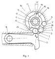
- FIG. 1 shows a schematic representation of a trigger mechanism with a rotor, Roll body and pawl.
- a cylindrical cutout 11 is provided, in which a rotor 12 is arranged.
- the rotor moves on a needle bearing with the rollers 13, all of which rest on a bearing shaft 14.
- the rotor 12 forms the outer ring of the needle bearing; the inner is formed by the bearing shaft 14.
- a cam 15 is attached, on the one hand, in which a reset bolt 16 is inserted, and on the other hand - approximately opposite the cam - an emergency nose 17 and a reset nose 18.
- the arrow attached to the rotor indicates the direction of rotation of the release movement.
- Emergency nose 17 and reset nose 18 are connected to each other with a rolling curve 19, the special properties of which will be discussed later.
- a rolling body 2 lies on the one hand on a surface 3 which can be displaced in parallel Roll curve 19 on, on the other hand on a roller stop 4, the part of the switch housing 10 is.
- the rolling body 2 ' is in a recess 7 of the switch housing 10 in a so-called catch position and lies in it.
- a damping pin 6 which acts as a stop for the reset lug 18 and serves to dampen the rotor movement.
- Fig. 2 shows a perspective view of the rotor.
- the rotor 12 with cams 15, reset bolt 16, emergency lug 17, reset lug 18 and the rolling curve 19 correspond to FIG. 1.
- the rolling curve 19 is limited on the one hand by an edge 19 'of the emergency lug 17 and on the other hand by an edge 19 "of the reset lug 18 and includes area 3 as part of it.
- an electrodynamic trigger mechanism is provided, which consists of a torque motor and is not described in detail here.
- the cam 15 of the rotor serves for the power transmission of the electrodynamic release mechanism by engaging in a recess in a coil former belonging to the torque motor.
- the cam 15 with the reset bolt 16 serves as a mass balance for the reset nose and emergency nose, so that no torques can arise under vibration.
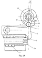
- 3A-3D show different phases of the triggering process in a schematic representation based on which the function of the trigger mechanism is explained.
- the roller body 2 touches the roller stop 4, lies on the surface 3 of the rotor 12 and is biased by the pawl 5 with its surface 1.
- the rolling body 2 can move away from the roller stop 4 in a small area, the rolling body always rolling between two concentric or parallel surfaces 1 and 3.
- the surfaces 1 and 3 which enable the rolling body to roll off freely, are referred to as parallel.
- the parallel surfaces are then replaced by concentric surfaces.
- Such rolling can be caused by environmental effects such as oscillations, vibrations, acceleration and shock and is referred to as 'mechanical noise' in analogy to signal noise in electrical engineering. In the area of these small movements, uncontrolled triggering processes are effectively suppressed.
- the rolling body 2 assumes a neutral position in this area.
- the rolling curve 19 has a radius R1 in this area, while the surface 1 of the pawl 5 has a radius R2.
- the movements of the moving rotor 12 are indicated by a short arrow on both sides.
- the pawl 5 has, on the side opposite the surface 1, a second surface 8 which locks a push rod 20 with a return spring 21, which is also mounted in the switch housing 10.
- 3B shows the last neutral position of the pretensioned release mechanism before the rolling body jumps.
- the rolling body 2 has clearly moved away from the roller stop 4, which is now brought about by the initialized triggering process.
- the triggering movement of the moving rotor 12 is indicated by an arrow on one side.
- the position of the rolling body 2 is characterized by the fact that it still rests on the surface 1 of the pawl 5 with radius R2, but is at the beginning of an edge zone 9, in which the rolling body is then in an unstable position.
- 3C shows a clearly diverging position of the pretensioned release mechanism shortly before the rolling body jumps.
- the rolling body 2 has moved further away from the roller stop 4, which is caused by the rotor 12 moving in the direction of the arrow.
- the areas 1 and 3 in the contact points of the rolling body 2 are no longer parallel but divergent, which is illustrated by the areas F1 and F3 entered.
- the areas F1 and F3 form the so-called divergence angle c.
- the rolling element gets into an unstable position in which it can jump at any moment. This 'transient' moment - as it is also called - is given when the tangent of the divergence angle becomes larger than approximately 2 ⁇ 10E-4.
- the rolling body 2 jumps before the emergency nose 17 touches it.
- the rolling process has slippage, which can be the case, for example, if an ant or parts thereof or any contaminants are on the surfaces 1 and / or 3, the timely jumping of the rolling body 2 is prevented or delayed.
- the emergency lug 17 of the rotor 12, which is activated, is then struck against the rolling element with the rolling curve 19 and the edge 19 'of the emergency lug pushes the rolling element away.
- the rolling body inevitably gets into the unstable or divergent area until it has to jump.
- 3D shows the end position of the rolling element in the triggered state.
- the rolling body 2 is in the catching position and lies in the recess 7.
- the pawl is located with the surface 1 behind the rolling body 2 and in front of the emergency nose 17.
- the rolling body 2 remains in contact with the surface 3 of the rotor.
- the rotor has meanwhile rotated at least 35 ° from the initial position into the final position and rests with the resetting lug 18 on the damping pin 6, which is preferably made of a plastic in order to dampen the moving mass.
- the pawl 5 has undergone a change in position of about 5 ° when released and released the push rod 20.
- the trigger mechanism With the function of the emergency nose 17, the trigger mechanism is given a further level of security, which makes it largely independent of any kind of contamination. It is noteworthy that the rolling of the rolling body takes place well before the angular position at which the emergency nose touches the rolling body. Only when unusual obstacles, such as an ants' flat rolling, influence the start of rolling and thereby delay the rolling process, does the emergency nose take action and push the rolling element into the divergent section.
- a reset mechanism ensures that the rolling body can be brought back into the tensioned state, or for the new device.
- a torsion spring is provided for this (not shown).
- the torsion spring ensures a firm and secure position of the rotor by means of a preload, so that one can speak of a 'secure starting position'.
- the torsion spring In the relaxed state, the torsion spring has an additional and thus increased pretension which is stored during the triggering process and which is provided for the return of the rotor in its initial position.
- the triggering process, or the switching process is indifferent in the phase of surface parallelism, and also is not triggered or initialized by oscillating rolling, as long as the divergent surface is not reached.
- FIG. 4 shows an exemplary embodiment of a trigger mechanism integrated in a valve device for the rapid opening of HDR extinguishing agent containers.
- the switch housing 10 is screwed to a valve housing 30, which in turn is tightly connected to the structure of a process container (not shown) via the bearing surfaces 31.
- a compressed gas bottle (not shown), which known extinguishing agents such as powder, Contains gas, water, etc., has a rotationally symmetrical neck 32, the Mouth through a retracted closure flap 33 with those guided in a groove 34 Seal 35 is closed via the flap bearing 36.
- the flap bearing 36 is located on the valve housing 30 nose-shaped projection 37 with a depression in which a hinge pin 38 lies and on which a main trap 40 rests pivotably.
- the upper part 42 of the main latch 40 has a narrow ledge 44, on which a projection 45 of the closure flap 33 rests in the locked state.
- the main trap 40 in turn continues into a round cross section and - designed as a second release lever 47 - lies with the end, which has a groove-shaped recess 48, on a plunger head 22 of the push rod 20.
- the push rod 20 is fixedly connected to the valve housing 30 by means of a push rod guide 23. The function of push rod and push rod guide will be described in detail later.
- the rotor 12, the roller body 2 and the pawl 5 can be seen in the switch housing 10 in the locked state.
- a locking bolt 50 attached, which is designed as an eccentric and with the main trap can be locked mechanically. This can function the trigger mechanism can be checked at any time without opening the closure flap 33 becomes.
- Fig. 5 shows the push rod with push rod head shown in section.
- the cylindrical push rod 20 is supported by sliding bushes 24 ′ and 24 ′′ which are embedded in the push rod guide 23 and in the switch housing 10. It has an almost continuous bore 25 which is provided with an internal thread 26 in the front bore part.
- the cylindrical push rod head 22 has an external thread 27 on one side and can be screwed to the pushrod, and on the other side the pusher head has two plane-parallel surfaces, by means of which it can be secured against rotation in a groove 48 which is attached to the lowermost end 47 of the main latch , In the middle of the plunger head there is a plate-shaped disk 49, which is provided for sealing the "extinguishing agent side" during the triggering process.
- This seal serves two O-rings 51 and 52, both of which are embedded in the tappet guide in grooves 51 'and 52' and separate the switching mechanism, which is accommodated in the switching housing 10, from the 'extinguishing agent side' of the valve housing 30. This is particularly advantageous because of the risk of contamination and protects the release mechanism from the extinguishing agents flowing out under high pressure.
- the O-ring 52 Located on the push rod 20 approximately in the middle of a ring 53 on which the return spring 21 rests and with the the push rod is returned to the starting position after the triggering is, the O-ring 52 cushions the snap-back of the push rod.
- the two O-rings namely that of Poetry on the one hand and damping on the other.
- the push rod On the side of the push rod facing away from the push rod head, the push rod has a hexagon bore 55 which is provided for the adjustment.
- the reliable functioning of the release system requires the mastery of all gap tolerances in the cascade of the power transmissions.
- the push rod 20 Via hexagon bore 55, the push rod 20 can be rotated in the thread 26 relative to the non-rotating plunger head 22 and thus a well-defined gap tolerance can be set between the end of the push rod and the pawl.
- a locking bolt 50 (FIG. 4), which is accessible outside the valve housing and can easily be rotated through 180 °, the eccentric coming to rest on the main latch and locking it.
- the eccentric position is recognized by two magnetic switches, one of which is active and the other is passive.
- the signals from the magnetic switches are connected in series, which enables a redundant arrangement to be achieved and is linked to the test release.
- the position of the rotor is detected on the one hand by an optical light barrier, which is arranged around the reset bolt.
- the torsion spring which rests on the reset pin and brings the rotor into the starting position, is monitored for breakage by being switched into an electrical circuit. This results in divergent redundancy.
- the signals from the magnetic switches, those from the optical light barrier and that for the torsion spring are fed to a coincidence circuit which only releases the current pulse to the torque motor, i.e. to trigger the test of the system, when the locking bolt and the rotor have been located in the correct positions.
- the method according to the invention is used when protective devices are used for the suppression of dust and / or gas explosions, as well Fires, in industrial plants, to trigger a latch cascade, which with the very quick opening of a pressurized flap of the extinguishing device ends.
Landscapes
- Engineering & Computer Science (AREA)
- General Engineering & Computer Science (AREA)
- Mechanical Engineering (AREA)
- Health & Medical Sciences (AREA)
- Public Health (AREA)
- Business, Economics & Management (AREA)
- Emergency Management (AREA)
- Train Traffic Observation, Control, And Security (AREA)
- Automotive Seat Belt Assembly (AREA)
- Prevention Of Fouling (AREA)
- Transmission Devices (AREA)
Claims (23)
- Procédé en vue d'un système de déclenchement mécanique muni de clapets mis en tension préalable, caractérisé en ce qu'une première surface guidée et mise en tension préalable (1) agit sur au moins un organe de roulement (2) avec une force (P), sachant que cette force (P) exercée sur l'organe de roulement (2) est transmise à une deuxième surface (3) logée de manière concentrique et rotative par rapport à la première surface (1), ou une deuxième surface (3) posée de manière parallèle et décalable par rapport à la première surface (1),
que l'organe de roulement (2), lors du mouvement de la deuxième surface (3), roule sur les deux surfaces (1, 3) jusqu'à ce qu'il parvient dans une zone marginale (9) de la première surface (1), dans laquelle le parallélisme des surfaces (1, 3) se transforme en non-parallélisme ou en divergence, si bien que l'organe de roulement (2) est expulsé et que les surfaces (1, 3) se rapprochent l'une de l'autre, et que le déclenchement est provoqué par le mouvement de la surface mise en tension préalable (1) vers la contre-surface, ou deuxième surface (3). - Procédé selon la revendication 1, caractérisée en ce que le mouvement de la deuxième surface (3) est accompli avec le minimum de frottements grâce à un roulement à rouleaux (12, 13, 14).
- Procédé selon la revendication 1 ou 2, caractérisée en ce que l'organe de roulement (2),, une fois qu'il a été expulsé ou après un saut, est rattrapé par une position de rattrapage qui la ramène sur sa position initiale à l'aide d'un "nez" de rappel (18) en tant que première limitation de la deuxième surface (3).
- Procédé selon l'une des revendications 1 à 3, caractérisée en ce qu'un rotor (12) est maintenu par une tension préalable d'un ressort de torsion sur une position initiale, et qu'il est ramené sur sa position initiale après le déclenchement.
- Procédé selon l'une des revendications 1 à 4, caractérisée en ce que l'organe de roulement (2) repose sur une voie de roulement qui se situe dans la zone de la position neutre de l'organe de roulement (2), là où les deux surfaces (1, 3) sont parallèles l'une à l'autre, et supprime ainsi un "cliquetis mécanique" et d'autres effets de l'environnement tels que des oscillations, l'accélération et des à-coups par rapport au déclenchement.
- Procédé selon l'une des revendications 1 à 5, caractérisée en ce que le mouvement de rotation de la deuxième surface (3) nécessaire pour le saut de l'organe de roulement (2) est généré par un moteur couple.
- Procédé selon l'une des revendications 1 à 6, caractérisée en ce que le saut de l'organe de roulement (2) s'effectue nettement avant la position angulaire à laquelle un nez de secours (17) touche l'organe de roulement (2).
- Procédé selon l'une des revendications 4 à 7, caractérisée en ce que l'organe de roulement (2) est acheminé par un nez de secours (17) sur le rotor (12) au moyen d'une deuxième délimitation de la deuxième surface (3), dans la zone marginale (9) de la première surface (1), si jamais l'opération de roulement a été retardée, et qu'un déclenchement est ainsi provoqué.
- Procédé selon la revendication 7 ou 8, caractérisée en ce que le saut de l'organe de roulement (2) libère un cliquet d'arrêt (5), étant donné que ce cliquet d'arrêt (5) se déplace en direction de la deuxième surface (3) et qu'en tant qu'élément d'une cascade de cliquets, il déclenche l'ensemble de la cascade avec un mécanisme d'assistance de puissance.
- Procédé selon l'une des revendications 1 à 9, caractérisée en ce que le réglage des tolérances de fente entre l'extrémité d'une tige de poussoir (20) et le cliquet d'arrêt (5) est obtenu par la rotation de la tige de poussoir (20) contre une tête de poussoir (22) logée d'une manière empêchant toute torsion.
- Procédé selon l'une des revendications 1 à 10, caractérisée en ce que la surveillance de la position du rotor (12) est assurée au moyen d'une barrière photoélectrique et du ressort de torsion électriquement conducteur, et que la surveillance de la position de la cheville de verrouillage (50) à l'aide d'un commutateur magnétique, qui génère des signaux de surveillance redondants et qui traite ceux-ci dans un circuit à coïncidence.
- Procédé selon la revendication 11, caractérisée en ce que le fonctionnement en toute sécurité du système de déclenchement à l'état de marche peut être vérifié pendant que le clapet (33) est verrouillé, ou que la trappe principale est verrouillée.
- Application du procédé selon l'une des revendications 1 à 12 pour l'ouverture d'extincteurs d'incendie en vue d'empêcher des explosions de poussière et/ ou de gaz, ainsi que des incendies dans des installations industrielles.
- Dispositif pour l'application du procédé selon l'une des revendications 1 à 12 sur un clapet, caractérisé en ce que dans un boítier de commutation (10) est placé au moins un organe de roulement (2) entre deux surfaces (1, 3), sachant qu'une première surface (1) est prévue pour l'application d'une tension préalable, et qu'une deuxième surface concentrique et pouvant être tordue (3) sur un rotor (12) est prévue pour le roulement, que la deuxième surface (3) est configurée comme élément d'une courbe de roulement (19) et comme segment d'un rotor (12), que ce dernier est installé et logé dans le boítier de commutation (10) et qu'il repose sur un roulement à aiguilles, et que cette première surface (1) comporte une zone marginale (9) dans laquelle le parallélisme des surfaces (1, 3) se transforme en non-parallélisme ou en divergence.
- Système de déclenchement selon la revendication 14, caractérisé en ce que des moyens sont prévus pour l'ajustement des tolérances de fente entre l'extrémité d'une tige de poussoir (20) et le cliquet d'arrêt (5).
- Système de déclenchement selon la revendication 14 ou 15, caractérisé en ce que des moyens sont prévus pour la surveillance des différentes positions du rotor (12) et de la cheville de verrouillage (50).
- Système de déclenchement selon l'une des revendications 14 à 16, caractérisé en ce que la première surface (1) dans une zone marginale (9) se transforme en une surface cylindrique dans laquelle se trouve le point de déclenchement auquel les surfaces (1, 3) ne sont plus concentriques l'une par rapport à l'autre, et auquel il est prévu que l'organe de roulement (2) qui roule va sauter dans la direction du roulement, et que la première surface (1) est configurée en tant que partie d'un cliquet d'arrêt (5).
- Système de déclenchement selon l'une des revendications 14 à 17, caractérisé en ce que le rotor (12), un nez de secours (17) comporte un nez de rappel (18), une courbe de roulement (19), un ergot (15) et une cheville de rappel (16), et que le rotor (12) se trouve dans une fraisure cylindrique (11) du boítier de commutation (10).
- Système de déclenchement selon l'une des revendications 14 à 18, caractérisé en ce que le rotor (12) vient en prise avec l'ergot (15) dans une fente d'un corps de bobine qui fait partie d'un moteur couple, sachant que ce dernier est prévu comme entraínement pour le mécanisme de déclenchement électrodynamique.
- Système de déclenchement selon l'une des revendications 14 à 19, caractérisé en ce qu'un évidement (7) dans le boítier de commutation (10) est prévu comme position de rattrapage pour l'organe de roulement (2), afin que cet organe de roulement (2) y repose après son saut.
- Système de déclenchement selon l'une des revendications 15 à 20, caractérisé en ce qu'une tige de poussoir rotative (20) avec une tête de poussoir résistante aux torsions (22) est installé entre le cliquet d'arrêt (5) et un piège principal (40) en guise de moyen d'ajustement, ce qui permet de régler le jeu entre l'extrémité de la tige de poussoir (20) et le cliquet d'arrêt (5).
- Système de déclenchement selon la revendication 21, caractérisé en ce que la tige de poussoir (20) comporte un filetage intérieur (26) qui recueille le filetage extérieur (27) de la tête de poussoir (22).
- Système de déclenchement selon l'une des revendications 16 à 22, caractérisé en ce qu'une barrière photoélectrique installée autour de la cheville de rappel (16) et un contrôle électrique de la conduite du ressort de torsion sont prévus comme moyens de surveillance pour l'identification de la position du rotor (12), des commutateurs magnétiques pour l'identification de la position de la cheville de verrouillage (50), ainsi qu'un circuit à coïncidence pour le traitement des signaux de surveillance.
Applications Claiming Priority (2)
| Application Number | Priority Date | Filing Date | Title |
|---|---|---|---|
| CH22699 | 1999-02-05 | ||
| CH22699 | 1999-02-05 |
Publications (2)
| Publication Number | Publication Date |
|---|---|
| EP1025878A1 EP1025878A1 (fr) | 2000-08-09 |
| EP1025878B1 true EP1025878B1 (fr) | 2002-07-03 |
Family
ID=4182166
Family Applications (1)
| Application Number | Title | Priority Date | Filing Date |
|---|---|---|---|
| EP99810938A Expired - Lifetime EP1025878B1 (fr) | 1999-02-05 | 1999-10-14 | Procédé et dispositif pour un mécanisme d'ouverture de clapets précontraints |
Country Status (3)
| Country | Link |
|---|---|
| EP (1) | EP1025878B1 (fr) |
| AT (1) | ATE219955T1 (fr) |
| DE (1) | DE59901918D1 (fr) |
Cited By (1)
| Publication number | Priority date | Publication date | Assignee | Title |
|---|---|---|---|---|
| CN111344045A (zh) * | 2017-11-14 | 2020-06-26 | 贺尔碧格维恩有限公司 | 灭火系统的触发设备 |
Families Citing this family (2)
| Publication number | Priority date | Publication date | Assignee | Title |
|---|---|---|---|---|
| AT522759B1 (de) | 2019-07-11 | 2021-09-15 | Hoerbiger Wien Gmbh | Dämpfungselement |
| CN119664972A (zh) * | 2024-12-13 | 2025-03-21 | 江苏亿阀股份有限公司 | 一种铸钢旋启式止回阀及其使用方法 |
Family Cites Families (7)
| Publication number | Priority date | Publication date | Assignee | Title |
|---|---|---|---|---|
| DE284194C (de) * | 1914-02-13 | 1915-05-14 | Beckmann Albert | Schlosssicherung mit einer in den riegel eingreifenden, auf elektrischem wege auslösbaren sperrklinke |
| FR1435945A (fr) * | 1965-03-09 | 1966-04-22 | Sud Aviation | Perfectionnements apportés aux dispositifs de commande et de verrouillage des obturateurs de vannes |
| DE1550428A1 (de) * | 1966-09-12 | 1970-04-23 | Otto Nitzschke | Durchgangs-Ventilarmatur fuer fluessige und gasfoermige Durchflussmedien mit einem von aussen betaetigten Ventilkegel |
| DE3322543C2 (de) * | 1982-06-30 | 1985-05-15 | Eltro GmbH, Gesellschaft für Strahlungstechnik, 6900 Heidelberg | Austrittsventil an Feuerlöschern |
| DE3819070C1 (en) * | 1988-06-04 | 1989-10-26 | Guenther 6116 Eppertshausen De Biergans | Safety-locking device for door leaves |
| DE69113547T2 (de) * | 1990-06-21 | 1996-05-15 | Thomas G Kotsiopoulos | Halbautomatische Druckgaswaffe. |
| DE4102049A1 (de) * | 1991-01-24 | 1992-07-30 | Kiekert Gmbh Co Kg | Kraftfahrzeugtuerverschluss |
-
1999
- 1999-10-14 DE DE59901918T patent/DE59901918D1/de not_active Expired - Lifetime
- 1999-10-14 AT AT99810938T patent/ATE219955T1/de active
- 1999-10-14 EP EP99810938A patent/EP1025878B1/fr not_active Expired - Lifetime
Cited By (3)
| Publication number | Priority date | Publication date | Assignee | Title |
|---|---|---|---|---|
| CN111344045A (zh) * | 2017-11-14 | 2020-06-26 | 贺尔碧格维恩有限公司 | 灭火系统的触发设备 |
| CN111344045B (zh) * | 2017-11-14 | 2022-08-26 | 贺尔碧格维恩有限公司 | 灭火系统的触发设备 |
| US11850459B2 (en) | 2017-11-14 | 2023-12-26 | Hoerbiger Wien Gmbh | Triggering device of an extinguishing system |
Also Published As
| Publication number | Publication date |
|---|---|
| ATE219955T1 (de) | 2002-07-15 |
| DE59901918D1 (de) | 2002-08-08 |
| EP1025878A1 (fr) | 2000-08-09 |
Similar Documents
| Publication | Publication Date | Title |
|---|---|---|
| DE19602690C1 (de) | Sicherheitsschalter | |
| EP0590295B1 (fr) | Dispositif pour verrouiller et libérer le pêne pivotant d'une ouvreuse de porte à courant permanent | |
| AT520540B1 (de) | Elektromagnetische Auslösung | |
| DE10391972T5 (de) | Roboterunfall-Schutzvorrichtung | |
| DE10308017A1 (de) | Steuervorrichtung mit Klappanker | |
| EP0421180B1 (fr) | Fixation de sécurité pour ski avec un circuit électronique | |
| DE4005777C1 (fr) | ||
| EP1895556A1 (fr) | Unité d'entraînement | |
| EP1025878A1 (fr) | Procédé et dispositif pour un mécanisme d'ouverture de clapets précontraints | |
| EP0882472A1 (fr) | Dispositif pour la suppression des explosions des poussières et/ou de gaz | |
| EP0733763A1 (fr) | Ferme-porte | |
| EP1247931B1 (fr) | Commande de séquence de fermeture | |
| DE4015797C2 (fr) | ||
| CH620729A5 (en) | Locking device for sealed-transfer doors | |
| DE202016003304U1 (de) | Selbsthemmende Bremse für ein(e) linear fahrende(s) Tür/Tor | |
| DE3143514C2 (de) | Sicherungseinrichtung für einen Explosivkörper | |
| DE19518824C1 (de) | Schalter | |
| DE3200323A1 (de) | Schnellschliessende klappe insbes. fuer rohrleitungen | |
| WO2002064927A1 (fr) | Regulateur de cycle de fermeture | |
| DE10107783B4 (de) | Schliessfolgeregler | |
| EP1409824A1 (fr) | R gulateur de cycle de fermeture | |
| DE10107457B4 (de) | Schließfolgeregler | |
| EP1022207B1 (fr) | Commande d' aiguillage | |
| AT513718B1 (de) | Sicherheitsvorrichtung | |
| DE102004049216A1 (de) | Steuerungsvorrichtung für eine Doppelklappe innerhalb einer Rohrleitung für Schüttgüter |
Legal Events
| Date | Code | Title | Description |
|---|---|---|---|
| PUAI | Public reference made under article 153(3) epc to a published international application that has entered the european phase |
Free format text: ORIGINAL CODE: 0009012 |
|
| 17P | Request for examination filed |
Effective date: 19991026 |
|
| AK | Designated contracting states |
Kind code of ref document: A1 Designated state(s): AT BE CH CY DE DK ES FI FR GB GR IE IT LI LU MC NL PT SE |
|
| AX | Request for extension of the european patent |
Free format text: AL;LT;LV;MK;RO;SI |
|
| 17Q | First examination report despatched |
Effective date: 20001103 |
|
| AKX | Designation fees paid |
Free format text: AT BE CH CY DE DK ES FI FR GB GR IE IT LI LU MC NL PT SE |
|
| GRAG | Despatch of communication of intention to grant |
Free format text: ORIGINAL CODE: EPIDOS AGRA |
|
| GRAG | Despatch of communication of intention to grant |
Free format text: ORIGINAL CODE: EPIDOS AGRA |
|
| GRAG | Despatch of communication of intention to grant |
Free format text: ORIGINAL CODE: EPIDOS AGRA |
|
| GRAH | Despatch of communication of intention to grant a patent |
Free format text: ORIGINAL CODE: EPIDOS IGRA |
|
| GRAH | Despatch of communication of intention to grant a patent |
Free format text: ORIGINAL CODE: EPIDOS IGRA |
|
| GRAA | (expected) grant |
Free format text: ORIGINAL CODE: 0009210 |
|
| AK | Designated contracting states |
Kind code of ref document: B1 Designated state(s): AT BE CH CY DE DK ES FI FR GB GR IE IT LI LU MC NL PT SE |
|
| PG25 | Lapsed in a contracting state [announced via postgrant information from national office to epo] |
Ref country code: NL Free format text: LAPSE BECAUSE OF FAILURE TO SUBMIT A TRANSLATION OF THE DESCRIPTION OR TO PAY THE FEE WITHIN THE PRESCRIBED TIME-LIMIT Effective date: 20020703 Ref country code: IT Free format text: LAPSE BECAUSE OF FAILURE TO SUBMIT A TRANSLATION OF THE DESCRIPTION OR TO PAY THE FEE WITHIN THE PRESCRIBED TIME-LIMIT;WARNING: LAPSES OF ITALIAN PATENTS WITH EFFECTIVE DATE BEFORE 2007 MAY HAVE OCCURRED AT ANY TIME BEFORE 2007. THE CORRECT EFFECTIVE DATE MAY BE DIFFERENT FROM THE ONE RECORDED. Effective date: 20020703 Ref country code: IE Free format text: LAPSE BECAUSE OF FAILURE TO SUBMIT A TRANSLATION OF THE DESCRIPTION OR TO PAY THE FEE WITHIN THE PRESCRIBED TIME-LIMIT Effective date: 20020703 Ref country code: GR Free format text: LAPSE BECAUSE OF FAILURE TO SUBMIT A TRANSLATION OF THE DESCRIPTION OR TO PAY THE FEE WITHIN THE PRESCRIBED TIME-LIMIT Effective date: 20020703 Ref country code: FI Free format text: LAPSE BECAUSE OF FAILURE TO SUBMIT A TRANSLATION OF THE DESCRIPTION OR TO PAY THE FEE WITHIN THE PRESCRIBED TIME-LIMIT Effective date: 20020703 |
|
| REF | Corresponds to: |
Ref document number: 219955 Country of ref document: AT Date of ref document: 20020715 Kind code of ref document: T |
|
| REG | Reference to a national code |
Ref country code: CH Ref legal event code: EP |
|
| REG | Reference to a national code |
Ref country code: IE Ref legal event code: FG4D Free format text: GERMAN |
|
| REF | Corresponds to: |
Ref document number: 59901918 Country of ref document: DE Date of ref document: 20020808 |
|
| PG25 | Lapsed in a contracting state [announced via postgrant information from national office to epo] |
Ref country code: SE Free format text: LAPSE BECAUSE OF FAILURE TO SUBMIT A TRANSLATION OF THE DESCRIPTION OR TO PAY THE FEE WITHIN THE PRESCRIBED TIME-LIMIT Effective date: 20021003 Ref country code: PT Free format text: LAPSE BECAUSE OF FAILURE TO SUBMIT A TRANSLATION OF THE DESCRIPTION OR TO PAY THE FEE WITHIN THE PRESCRIBED TIME-LIMIT Effective date: 20021003 Ref country code: DK Free format text: LAPSE BECAUSE OF FAILURE TO SUBMIT A TRANSLATION OF THE DESCRIPTION OR TO PAY THE FEE WITHIN THE PRESCRIBED TIME-LIMIT Effective date: 20021003 |
|
| GBT | Gb: translation of ep patent filed (gb section 77(6)(a)/1977) |
Effective date: 20020912 |
|
| PG25 | Lapsed in a contracting state [announced via postgrant information from national office to epo] |
Ref country code: LU Free format text: LAPSE BECAUSE OF NON-PAYMENT OF DUE FEES Effective date: 20021014 |
|
| PG25 | Lapsed in a contracting state [announced via postgrant information from national office to epo] |
Ref country code: CY Free format text: LAPSE BECAUSE OF FAILURE TO SUBMIT A TRANSLATION OF THE DESCRIPTION OR TO PAY THE FEE WITHIN THE PRESCRIBED TIME-LIMIT Effective date: 20021031 Ref country code: BE Free format text: LAPSE BECAUSE OF NON-PAYMENT OF DUE FEES Effective date: 20021031 |
|
| NLV1 | Nl: lapsed or annulled due to failure to fulfill the requirements of art. 29p and 29m of the patents act | ||
| ET | Fr: translation filed | ||
| REG | Reference to a national code |
Ref country code: CH Ref legal event code: NV Representative=s name: DILTEC AG |
|
| PG25 | Lapsed in a contracting state [announced via postgrant information from national office to epo] |
Ref country code: ES Free format text: LAPSE BECAUSE OF FAILURE TO SUBMIT A TRANSLATION OF THE DESCRIPTION OR TO PAY THE FEE WITHIN THE PRESCRIBED TIME-LIMIT Effective date: 20030130 |
|
| REG | Reference to a national code |
Ref country code: IE Ref legal event code: FD4D Ref document number: 1025878E Country of ref document: IE |
|
| BERE | Be: lapsed |
Owner name: *INCOM EXPLOSIONSSCHUTZ A.G. Effective date: 20021031 |
|
| PG25 | Lapsed in a contracting state [announced via postgrant information from national office to epo] |
Ref country code: MC Free format text: LAPSE BECAUSE OF NON-PAYMENT OF DUE FEES Effective date: 20030501 |
|
| PLBE | No opposition filed within time limit |
Free format text: ORIGINAL CODE: 0009261 |
|
| STAA | Information on the status of an ep patent application or granted ep patent |
Free format text: STATUS: NO OPPOSITION FILED WITHIN TIME LIMIT |
|
| 26N | No opposition filed |
Effective date: 20030404 |
|
| REG | Reference to a national code |
Ref country code: CH Ref legal event code: PUE Owner name: IEP TECHNOLOGIES, LLC, US Free format text: FORMER OWNER: INCOM EXPLOSIONSSCHUTZ AG, CH Ref country code: CH Ref legal event code: NV Representative=s name: BUGNION S.A., CH |
|
| REG | Reference to a national code |
Ref country code: DE Ref legal event code: R081 Ref document number: 59901918 Country of ref document: DE Owner name: IEP TECHNOLOGIES, LLC (N.D.GES.D. STAATES DELA, US Free format text: FORMER OWNER: INCOM EXPLOSIONSSCHUTZ AG, OLTEN, CH |
|
| REG | Reference to a national code |
Ref country code: GB Ref legal event code: 732E Free format text: REGISTERED BETWEEN 20150702 AND 20150708 |
|
| REG | Reference to a national code |
Ref country code: FR Ref legal event code: TP Owner name: IEP TECHNOLOGIES, US Effective date: 20151002 |
|
| REG | Reference to a national code |
Ref country code: FR Ref legal event code: PLFP Year of fee payment: 17 |
|
| REG | Reference to a national code |
Ref country code: AT Ref legal event code: PC Ref document number: 219955 Country of ref document: AT Kind code of ref document: T Owner name: IEP TECHNOLOGIES, LLC, US Effective date: 20151218 |
|
| REG | Reference to a national code |
Ref country code: FR Ref legal event code: PLFP Year of fee payment: 18 |
|
| PGFP | Annual fee paid to national office [announced via postgrant information from national office to epo] |
Ref country code: GB Payment date: 20161028 Year of fee payment: 18 Ref country code: CH Payment date: 20161020 Year of fee payment: 18 Ref country code: FR Payment date: 20161028 Year of fee payment: 18 |
|
| PGFP | Annual fee paid to national office [announced via postgrant information from national office to epo] |
Ref country code: AT Payment date: 20161025 Year of fee payment: 18 |
|
| REG | Reference to a national code |
Ref country code: CH Ref legal event code: PL |
|
| REG | Reference to a national code |
Ref country code: AT Ref legal event code: MM01 Ref document number: 219955 Country of ref document: AT Kind code of ref document: T Effective date: 20171014 |
|
| GBPC | Gb: european patent ceased through non-payment of renewal fee |
Effective date: 20171014 |
|
| REG | Reference to a national code |
Ref country code: FR Ref legal event code: ST Effective date: 20180629 |
|
| PG25 | Lapsed in a contracting state [announced via postgrant information from national office to epo] |
Ref country code: GB Free format text: LAPSE BECAUSE OF NON-PAYMENT OF DUE FEES Effective date: 20171014 Ref country code: LI Free format text: LAPSE BECAUSE OF NON-PAYMENT OF DUE FEES Effective date: 20171031 Ref country code: CH Free format text: LAPSE BECAUSE OF NON-PAYMENT OF DUE FEES Effective date: 20171031 |
|
| PG25 | Lapsed in a contracting state [announced via postgrant information from national office to epo] |
Ref country code: FR Free format text: LAPSE BECAUSE OF NON-PAYMENT OF DUE FEES Effective date: 20171031 Ref country code: AT Free format text: LAPSE BECAUSE OF NON-PAYMENT OF DUE FEES Effective date: 20171014 |
|
| PGFP | Annual fee paid to national office [announced via postgrant information from national office to epo] |
Ref country code: DE Payment date: 20181024 Year of fee payment: 20 |
|
| REG | Reference to a national code |
Ref country code: DE Ref legal event code: R071 Ref document number: 59901918 Country of ref document: DE |