EP1026031A2 - Infrarotes Zweiband-Sichtsystem für Kraftfahrzeuge - Google Patents
Infrarotes Zweiband-Sichtsystem für Kraftfahrzeuge Download PDFInfo
- Publication number
- EP1026031A2 EP1026031A2 EP00830062A EP00830062A EP1026031A2 EP 1026031 A2 EP1026031 A2 EP 1026031A2 EP 00830062 A EP00830062 A EP 00830062A EP 00830062 A EP00830062 A EP 00830062A EP 1026031 A2 EP1026031 A2 EP 1026031A2
- Authority
- EP
- European Patent Office
- Prior art keywords
- infrared
- radiation
- vision system
- scene
- band
- Prior art date
- Legal status (The legal status is an assumption and is not a legal conclusion. Google has not performed a legal analysis and makes no representation as to the accuracy of the status listed.)
- Granted
Links
- 230000004438 eyesight Effects 0.000 title claims abstract description 18
- 230000005855 radiation Effects 0.000 claims abstract description 34
- 238000012634 optical imaging Methods 0.000 claims description 10
- 239000011159 matrix material Substances 0.000 claims description 4
- 239000006185 dispersion Substances 0.000 claims description 2
- 230000003287 optical effect Effects 0.000 description 2
- 238000010276 construction Methods 0.000 description 1
- 238000005516 engineering process Methods 0.000 description 1
- 230000004297 night vision Effects 0.000 description 1
- 230000002093 peripheral effect Effects 0.000 description 1
Images

Classifications
-
- B—PERFORMING OPERATIONS; TRANSPORTING
- B60—VEHICLES IN GENERAL
- B60Q—ARRANGEMENT OF SIGNALLING OR LIGHTING DEVICES, THE MOUNTING OR SUPPORTING THEREOF OR CIRCUITS THEREFOR, FOR VEHICLES IN GENERAL
- B60Q1/00—Arrangement of optical signalling or lighting devices, the mounting or supporting thereof or circuits therefor
- B60Q1/0017—Devices integrating an element dedicated to another function
- B60Q1/0023—Devices integrating an element dedicated to another function the element being a sensor, e.g. distance sensor, camera
-
- B—PERFORMING OPERATIONS; TRANSPORTING
- B60—VEHICLES IN GENERAL
- B60Q—ARRANGEMENT OF SIGNALLING OR LIGHTING DEVICES, THE MOUNTING OR SUPPORTING THEREOF OR CIRCUITS THEREFOR, FOR VEHICLES IN GENERAL
- B60Q1/00—Arrangement of optical signalling or lighting devices, the mounting or supporting thereof or circuits therefor
- B60Q1/02—Arrangement of optical signalling or lighting devices, the mounting or supporting thereof or circuits therefor the devices being primarily intended to illuminate the way ahead or to illuminate other areas of way or environments
- B60Q1/04—Arrangement of optical signalling or lighting devices, the mounting or supporting thereof or circuits therefor the devices being primarily intended to illuminate the way ahead or to illuminate other areas of way or environments the devices being headlights
- B60Q1/14—Arrangement of optical signalling or lighting devices, the mounting or supporting thereof or circuits therefor the devices being primarily intended to illuminate the way ahead or to illuminate other areas of way or environments the devices being headlights having dimming means
-
- B—PERFORMING OPERATIONS; TRANSPORTING
- B60—VEHICLES IN GENERAL
- B60Q—ARRANGEMENT OF SIGNALLING OR LIGHTING DEVICES, THE MOUNTING OR SUPPORTING THEREOF OR CIRCUITS THEREFOR, FOR VEHICLES IN GENERAL
- B60Q1/00—Arrangement of optical signalling or lighting devices, the mounting or supporting thereof or circuits therefor
- B60Q1/02—Arrangement of optical signalling or lighting devices, the mounting or supporting thereof or circuits therefor the devices being primarily intended to illuminate the way ahead or to illuminate other areas of way or environments
- B60Q1/04—Arrangement of optical signalling or lighting devices, the mounting or supporting thereof or circuits therefor the devices being primarily intended to illuminate the way ahead or to illuminate other areas of way or environments the devices being headlights
- B60Q1/18—Arrangement of optical signalling or lighting devices, the mounting or supporting thereof or circuits therefor the devices being primarily intended to illuminate the way ahead or to illuminate other areas of way or environments the devices being headlights being additional front lights
- B60Q1/20—Fog lights
Definitions
- the present invention relates to infrared vision systems for motor vehicles, of the type comprising an infrared-radiation detecting device designed to be mounted on the front of a motor vehicle, the device including infrared sensor means designed to emit electrical signals according to the infrared radiation detected, optical imaging means for focusing the infrared image of the scene in front of the vehicle on said sensor means, electronic means for processing the signals issued by the sensor means, and image-displaying means controlled by said electronic means.
- infrared vision systems that have so far been produced exploit infrared radiation in a wave band ranging from 8 to 14 micron (longwave window - LW), which is emitted spontaneously to a variable extent by all the objects of the scene in front of the motor vehicle. These systems do not enable optimal results to be achieved, especially in particular conditions, such as in the presence of fog.
- the purpose of the present invention is to propose a new infrared vision system for motor vehicles that enables improvement of night vision in all conditions, and in particular in the presence of thick fog.
- the subject of the invention is a vision system of the type specified above, characterized in that the aforesaid optical imaging means are designed to focus both infrared radiation in a first wave band, corresponding to the radiation spontaneously emitted by the objects of the scene in front of the motor vehicle, and infrared radiation in a second wave band, which is in part emitted spontaneously by the objects of the scene, and in part is emitted by a source of infrared radiation which forms part of the vision system and is reflected by the objects in front of the vehicle towards said detecting device.
- the radiation emitted spontaneously by the scene falls within a wavelength range of between 8 and 14 micron (longwave window - LW).
- the above-mentioned infrared-radiation source forming part of the system is designed to emit radiation in a wave band of between 3 and 5 micron (midwave window - MW). This radiation is reflected by the objects of the scene, and is then detected by the sensor means forming part of the system according to the invention.
- the aforesaid optical imaging means comprise two optical imaging devices, which are combined in such a way as to minimize dispersion between the two aforesaid wave bands, and a discriminator designed to send to the sensor means alternately the radiation in the first band and the radiation in the second band (for example, a discriminator of a rotary type).
- the above-mentioned sensor means consist of a matrix of non-cooled thermal sensors, of a type chosen from among pyro-electric sensors, resistive bolometers, ferro-electric bolometers, and thermo-electric sensors of a conventional type.
- the said infrared-radiation source consists of a headlight of the motor vehicle which has a front element that is at least in part transparent to infrared radiation.
- the detecting device of the vision system according to the invention is built into the said headlight of the motor vehicle.
- the control electronics forming part of the system according to the invention makes it possible to read, interpret and superimpose the infrared images in the two bands acquired by the sensors, so presenting a single infrared image of the scene on the display means at output.
- the main advantage of the system according to the invention is that it enables simultaneous exploitation of the greater intensity of the IR image in the 8-14 micron LW window and the greater contrast of the IR image in the 3-4 micron MW window in the temperature range of interest.
- the reference number 1 designates, as a whole, a motor-vehicle headlight comprising a rigid casing 2 inside which is set a headlight 3 including a parabolic dish 4 associated to a lamp 5.
- the reference number 6 designates the transparent front element of the headlight 3, which presents, in the case of the example illustrated, peripheral windows 7 that are transparent to infrared radiation.
- the lamp 5 is chosen so as to emit infrared radiation in a wave band of between 3 and 5 micron.
- the body 2 of the headlight 1 also includes an infrared-radiation detecting device 8 comprising infrared sensor means 9 consisting of a matrix of non-cooled thermal sensors, for example pyro-electric sensors or resistive bolometers, or ferro-electric bolometers, or thermoelectric sensors of a conventional type, which are designed to send electrical signals according to the infrared image detected to a processing electronic control unit 10.
- the detecting device 8 comprises an optical imaging system 11 which is designed to focus on the sensors 9 both the infrared image in the 3-5 micron wave band, which is reflected by the objects of the scene in front of the vehicle, and the infrared radiation in the 8-14 micron wave band, which is emitted spontaneously by the objects of the scene.
- the detecting device 8 has, at the front, a window 13 which is transparent to infrared radiation.
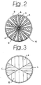
- the said optical discriminator 14 consists of a disc having sectors A that are transparent to infrared radiation of between 8 and 14 micron, sectors B that are transparent to infrared radiation of between 3 and 5 micron, and opaque sectors C that clearly divide the sectors A from the sectors B.
- the rotary discriminator 14 is used to send alternately the 8-14 micron infrared radiation and the 3-5 micron infrared radiation to the sensor means 9.
- the electronic control unit 10 is designed to read, interpret and superimpose the infrared images in the two bands acquired by the sensors, presenting at output, on a display 15 provided on the motor vehicle dashboard or on the windscreen itself, according to a HEAD-UP type technology, a single infrared image of the scene.
- the main advantage of the device lies in the fact that it enables simultaneous exploitation of the greater intensity of the IR image in the 8-14 micron band and the greater contrast of the IR image in the 3-5 micron band.
- the source of 3-5 micron IR radiation could also be a dedicated source, distinct from the vehicle headlight.
Landscapes
- Engineering & Computer Science (AREA)
- Mechanical Engineering (AREA)
- Photometry And Measurement Of Optical Pulse Characteristics (AREA)
- Traffic Control Systems (AREA)
- Closed-Circuit Television Systems (AREA)
- Optical Radar Systems And Details Thereof (AREA)
- Non-Portable Lighting Devices Or Systems Thereof (AREA)
- Lighting Device Outwards From Vehicle And Optical Signal (AREA)
Applications Claiming Priority (2)
| Application Number | Priority Date | Filing Date | Title |
|---|---|---|---|
| ITTO990073 IT1307132B1 (it) | 1999-02-02 | 1999-02-02 | Sistema di visione ad infrarosso a doppia banda per autoveicoli. |
| ITTO990073 | 1999-02-02 |
Publications (3)
| Publication Number | Publication Date |
|---|---|
| EP1026031A2 true EP1026031A2 (de) | 2000-08-09 |
| EP1026031A3 EP1026031A3 (de) | 2003-01-22 |
| EP1026031B1 EP1026031B1 (de) | 2004-01-02 |
Family
ID=11417413
Family Applications (1)
| Application Number | Title | Priority Date | Filing Date |
|---|---|---|---|
| EP20000830062 Expired - Lifetime EP1026031B1 (de) | 1999-02-02 | 2000-01-28 | Infrarotes Zweiband-Sichtsystem für Kraftfahrzeuge |
Country Status (4)
| Country | Link |
|---|---|
| EP (1) | EP1026031B1 (de) |
| DE (1) | DE60007463T2 (de) |
| ES (1) | ES2211494T3 (de) |
| IT (1) | IT1307132B1 (de) |
Cited By (13)
| Publication number | Priority date | Publication date | Assignee | Title |
|---|---|---|---|---|
| WO2005029125A1 (de) * | 2003-09-19 | 2005-03-31 | Robert Bosch Gmbh | Verfahren zur verbesserung der sicht in einem kraftfahrzeug |
| US20130325323A1 (en) | 1998-10-22 | 2013-12-05 | American Vehicular Sciences | Vehicle software upgrade techniques |
| US8820782B2 (en) | 1995-06-07 | 2014-09-02 | American Vehicular Sciences Llc | Arrangement for sensing weight of an occupying item in vehicular seat |
| US8880296B2 (en) | 1994-05-23 | 2014-11-04 | American Vehicular Sciences, LLC | Techniques for improving safe operation of a vehicle |
| US8892271B2 (en) | 1997-10-22 | 2014-11-18 | American Vehicular Sciences Llc | Information Transmittal Techniques for Vehicles |
| US9008854B2 (en) | 1995-06-07 | 2015-04-14 | American Vehicular Sciences Llc | Vehicle component control methods and systems |
| US9022417B2 (en) | 1995-12-12 | 2015-05-05 | American Vehicular Sciences Llc | Single side curtain airbag for vehicles |
| US9102220B2 (en) | 1992-05-05 | 2015-08-11 | American Vehicular Sciences Llc | Vehicular crash notification system |
| US9177476B2 (en) | 1997-10-22 | 2015-11-03 | American Vehicular Sciences Llc | Method and system for guiding a person to a location |
| US9443358B2 (en) | 1995-06-07 | 2016-09-13 | Automotive Vehicular Sciences LLC | Vehicle software upgrade techniques |
| EP3428510A1 (de) * | 2017-07-10 | 2019-01-16 | LG Electronics Inc. | Lampe für fahrzeug sowie fahrzeug |
| US10358057B2 (en) | 1997-10-22 | 2019-07-23 | American Vehicular Sciences Llc | In-vehicle signage techniques |
| US10573093B2 (en) | 1995-06-07 | 2020-02-25 | Automotive Technologies International, Inc. | Vehicle computer design and use techniques for receiving navigation software |
Family Cites Families (3)
| Publication number | Priority date | Publication date | Assignee | Title |
|---|---|---|---|---|
| DE4032927A1 (de) * | 1990-10-17 | 1992-04-30 | Bosch Gmbh Robert | Vorrichtung zur verbesserung der sichtverhaeltnisse in einem kraftfahrzeug |
| FR2730035B1 (fr) * | 1995-01-30 | 1997-04-18 | Valeo Vision | Projecteur infrarouge pour systeme d'aide a la vision pour vehicule automobile et systeme d'aide a la vision le comportant |
| US5796514A (en) * | 1996-03-04 | 1998-08-18 | Raytheon Ti Systems, Inc. | Infrared zoom lens assembly having a variable F/number |
-
1999
- 1999-02-02 IT ITTO990073 patent/IT1307132B1/it active
-
2000
- 2000-01-28 EP EP20000830062 patent/EP1026031B1/de not_active Expired - Lifetime
- 2000-01-28 ES ES00830062T patent/ES2211494T3/es not_active Expired - Lifetime
- 2000-01-28 DE DE2000607463 patent/DE60007463T2/de not_active Expired - Lifetime
Non-Patent Citations (1)
| Title |
|---|
| None |
Cited By (19)
| Publication number | Priority date | Publication date | Assignee | Title |
|---|---|---|---|---|
| US9102220B2 (en) | 1992-05-05 | 2015-08-11 | American Vehicular Sciences Llc | Vehicular crash notification system |
| US8880296B2 (en) | 1994-05-23 | 2014-11-04 | American Vehicular Sciences, LLC | Techniques for improving safe operation of a vehicle |
| US9593521B2 (en) | 1995-06-07 | 2017-03-14 | American Vehicular Sciences Llc | Vehicle component control methods and systems |
| US8820782B2 (en) | 1995-06-07 | 2014-09-02 | American Vehicular Sciences Llc | Arrangement for sensing weight of an occupying item in vehicular seat |
| US10573093B2 (en) | 1995-06-07 | 2020-02-25 | Automotive Technologies International, Inc. | Vehicle computer design and use techniques for receiving navigation software |
| US9443358B2 (en) | 1995-06-07 | 2016-09-13 | Automotive Vehicular Sciences LLC | Vehicle software upgrade techniques |
| US9008854B2 (en) | 1995-06-07 | 2015-04-14 | American Vehicular Sciences Llc | Vehicle component control methods and systems |
| US9022417B2 (en) | 1995-12-12 | 2015-05-05 | American Vehicular Sciences Llc | Single side curtain airbag for vehicles |
| US9043093B2 (en) | 1995-12-12 | 2015-05-26 | American Vehicular Sciences Llc | Single side curtain airbag for vehicles |
| US9177476B2 (en) | 1997-10-22 | 2015-11-03 | American Vehicular Sciences Llc | Method and system for guiding a person to a location |
| US8892271B2 (en) | 1997-10-22 | 2014-11-18 | American Vehicular Sciences Llc | Information Transmittal Techniques for Vehicles |
| US10051411B2 (en) | 1997-10-22 | 2018-08-14 | American Vehicular Sciences Llc | Method and system for guiding a person to a location |
| US10358057B2 (en) | 1997-10-22 | 2019-07-23 | American Vehicular Sciences Llc | In-vehicle signage techniques |
| US10240935B2 (en) | 1998-10-22 | 2019-03-26 | American Vehicular Sciences Llc | Vehicle software upgrade techniques |
| US20130325323A1 (en) | 1998-10-22 | 2013-12-05 | American Vehicular Sciences | Vehicle software upgrade techniques |
| US7400266B2 (en) | 2003-09-19 | 2008-07-15 | Robert Bosch Gmbh | Method for improving vision in a motor vehicle |
| WO2005029125A1 (de) * | 2003-09-19 | 2005-03-31 | Robert Bosch Gmbh | Verfahren zur verbesserung der sicht in einem kraftfahrzeug |
| EP3428510A1 (de) * | 2017-07-10 | 2019-01-16 | LG Electronics Inc. | Lampe für fahrzeug sowie fahrzeug |
| US10641453B2 (en) | 2017-07-10 | 2020-05-05 | Zkw Group Gmbh | Lamp for vehicle and vehicle |
Also Published As
| Publication number | Publication date |
|---|---|
| ES2211494T3 (es) | 2004-07-16 |
| ITTO990073A1 (it) | 2000-08-02 |
| IT1307132B1 (it) | 2001-10-29 |
| EP1026031B1 (de) | 2004-01-02 |
| EP1026031A3 (de) | 2003-01-22 |
| DE60007463D1 (de) | 2004-02-05 |
| DE60007463T2 (de) | 2004-11-11 |
Similar Documents
| Publication | Publication Date | Title |
|---|---|---|
| EP1026031B1 (de) | Infrarotes Zweiband-Sichtsystem für Kraftfahrzeuge | |
| US6420704B1 (en) | Method and system for improving camera infrared sensitivity using digital zoom | |
| JP4718614B2 (ja) | 光学式レインセンサが組み込まれているヘッドライトモジュール | |
| US10390004B2 (en) | Stereo gated imaging system and method | |
| US7015470B2 (en) | Active night vision cooling system | |
| US7368714B2 (en) | Active night vision thermal control system using wavelength-temperature characteristic of light source | |
| KR100682523B1 (ko) | 반도체 광 센서들을 가진 차량 기기 제어장치 | |
| US6703925B2 (en) | Monitoring device for vehicles, in particular, motor vehicles | |
| US20190137331A1 (en) | Imaging apparatus | |
| US20020148986A1 (en) | Differential imaging rain sensor | |
| US10725216B2 (en) | Onboard camera | |
| US10132971B2 (en) | Vehicle camera with multiple spectral filters | |
| US9845052B2 (en) | Electronic camera and motor vehicle using such a camera | |
| EP2999207B1 (de) | Optisches fahrzeugsensorsystem | |
| US11377028B2 (en) | Detection system and a vehicle therewith | |
| US20220057269A1 (en) | Multi-sensor using a thermal camera | |
| US20180205859A1 (en) | Vehicle vision system camera with semi-reflective and semi-transmissive element | |
| US20230343802A1 (en) | Solid-state imaging device and electronic device | |
| US6969855B2 (en) | Active night vision thermal control system | |
| WO2023100640A1 (ja) | 半導体装置および信号処理方法、並びにプログラム | |
| JP2017083584A (ja) | 撮像装置 | |
| Keerthana et al. | Night Vision for HVAC Duct Monitoring Bot | |
| JP2008168704A (ja) | 車載カメラ装置 |
Legal Events
| Date | Code | Title | Description |
|---|---|---|---|
| PUAI | Public reference made under article 153(3) epc to a published international application that has entered the european phase |
Free format text: ORIGINAL CODE: 0009012 |
|
| AK | Designated contracting states |
Kind code of ref document: A2 Designated state(s): AT BE CH CY DE DK ES FI FR GB GR IE IT LI LU MC NL PT SE |
|
| AX | Request for extension of the european patent |
Free format text: AL;LT;LV;MK;RO;SI |
|
| PUAL | Search report despatched |
Free format text: ORIGINAL CODE: 0009013 |
|
| AK | Designated contracting states |
Kind code of ref document: A3 Designated state(s): AT BE CH CY DE DK ES FI FR GB GR IE IT LI LU MC NL PT SE |
|
| AX | Request for extension of the european patent |
Free format text: AL;LT;LV;MK;RO;SI |
|
| RIC1 | Information provided on ipc code assigned before grant |
Free format text: 7B 60Q 1/20 A, 7B 62D 15/02 B, 7B 60Q 1/00 B |
|
| 17P | Request for examination filed |
Effective date: 20030402 |
|
| GRAH | Despatch of communication of intention to grant a patent |
Free format text: ORIGINAL CODE: EPIDOS IGRA |
|
| AKX | Designation fees paid |
Designated state(s): DE ES FR GB IT SE |
|
| GRAS | Grant fee paid |
Free format text: ORIGINAL CODE: EPIDOSNIGR3 |
|
| GRAA | (expected) grant |
Free format text: ORIGINAL CODE: 0009210 |
|
| AK | Designated contracting states |
Kind code of ref document: B1 Designated state(s): DE ES FR GB IT SE |
|
| REG | Reference to a national code |
Ref country code: GB Ref legal event code: FG4D |
|
| REG | Reference to a national code |
Ref country code: IE Ref legal event code: FG4D |
|
| REG | Reference to a national code |
Ref country code: SE Ref legal event code: TRGR |
|
| REF | Corresponds to: |
Ref document number: 60007463 Country of ref document: DE Date of ref document: 20040205 Kind code of ref document: P |
|
| REG | Reference to a national code |
Ref country code: ES Ref legal event code: FG2A Ref document number: 2211494 Country of ref document: ES Kind code of ref document: T3 |
|
| ET | Fr: translation filed | ||
| PLBE | No opposition filed within time limit |
Free format text: ORIGINAL CODE: 0009261 |
|
| STAA | Information on the status of an ep patent application or granted ep patent |
Free format text: STATUS: NO OPPOSITION FILED WITHIN TIME LIMIT |
|
| REG | Reference to a national code |
Ref country code: IE Ref legal event code: MM4A |
|
| 26N | No opposition filed |
Effective date: 20041005 |
|
| PGFP | Annual fee paid to national office [announced via postgrant information from national office to epo] |
Ref country code: ES Payment date: 20080218 Year of fee payment: 9 |
|
| PGFP | Annual fee paid to national office [announced via postgrant information from national office to epo] |
Ref country code: SE Payment date: 20080104 Year of fee payment: 9 |
|
| EUG | Se: european patent has lapsed | ||
| REG | Reference to a national code |
Ref country code: ES Ref legal event code: FD2A Effective date: 20090129 |
|
| PG25 | Lapsed in a contracting state [announced via postgrant information from national office to epo] |
Ref country code: ES Free format text: LAPSE BECAUSE OF NON-PAYMENT OF DUE FEES Effective date: 20090129 |
|
| PG25 | Lapsed in a contracting state [announced via postgrant information from national office to epo] |
Ref country code: SE Free format text: LAPSE BECAUSE OF NON-PAYMENT OF DUE FEES Effective date: 20090129 |
|
| PGFP | Annual fee paid to national office [announced via postgrant information from national office to epo] |
Ref country code: GB Payment date: 20110126 Year of fee payment: 12 |
|
| PGFP | Annual fee paid to national office [announced via postgrant information from national office to epo] |
Ref country code: IT Payment date: 20120109 Year of fee payment: 13 |
|
| GBPC | Gb: european patent ceased through non-payment of renewal fee |
Effective date: 20120128 |
|
| PG25 | Lapsed in a contracting state [announced via postgrant information from national office to epo] |
Ref country code: GB Free format text: LAPSE BECAUSE OF NON-PAYMENT OF DUE FEES Effective date: 20120128 |
|
| PGFP | Annual fee paid to national office [announced via postgrant information from national office to epo] |
Ref country code: DE Payment date: 20130123 Year of fee payment: 14 Ref country code: FR Payment date: 20130204 Year of fee payment: 14 |
|
| PG25 | Lapsed in a contracting state [announced via postgrant information from national office to epo] |
Ref country code: IT Free format text: LAPSE BECAUSE OF NON-PAYMENT OF DUE FEES Effective date: 20130128 |
|
| REG | Reference to a national code |
Ref country code: DE Ref legal event code: R119 Ref document number: 60007463 Country of ref document: DE |
|
| REG | Reference to a national code |
Ref country code: DE Ref legal event code: R119 Ref document number: 60007463 Country of ref document: DE Effective date: 20140801 |
|
| PG25 | Lapsed in a contracting state [announced via postgrant information from national office to epo] |
Ref country code: DE Free format text: LAPSE BECAUSE OF NON-PAYMENT OF DUE FEES Effective date: 20140801 |
|
| REG | Reference to a national code |
Ref country code: FR Ref legal event code: ST Effective date: 20140930 |
|
| PG25 | Lapsed in a contracting state [announced via postgrant information from national office to epo] |
Ref country code: FR Free format text: LAPSE BECAUSE OF NON-PAYMENT OF DUE FEES Effective date: 20140131 |