EP1026128A2 - Procédé de fabrication de tubes cylindriques coupés de préférence à partir de tubes en verre et appareil pour appliquer ledit procédé - Google Patents
Procédé de fabrication de tubes cylindriques coupés de préférence à partir de tubes en verre et appareil pour appliquer ledit procédé Download PDFInfo
- Publication number
- EP1026128A2 EP1026128A2 EP99124694A EP99124694A EP1026128A2 EP 1026128 A2 EP1026128 A2 EP 1026128A2 EP 99124694 A EP99124694 A EP 99124694A EP 99124694 A EP99124694 A EP 99124694A EP 1026128 A2 EP1026128 A2 EP 1026128A2
- Authority
- EP
- European Patent Office
- Prior art keywords
- cylinder tube
- tube sections
- tubes
- cylinder
- support rollers
- Prior art date
- Legal status (The legal status is an assumption and is not a legal conclusion. Google has not performed a legal analysis and makes no representation as to the accuracy of the status listed.)
- Granted
Links
Images


Classifications
-
- C—CHEMISTRY; METALLURGY
- C03—GLASS; MINERAL OR SLAG WOOL
- C03B—MANUFACTURE, SHAPING, OR SUPPLEMENTARY PROCESSES
- C03B23/00—Re-forming shaped glass
- C03B23/04—Re-forming tubes or rods
- C03B23/09—Reshaping the ends, e.g. as grooves, threads or mouths
-
- C—CHEMISTRY; METALLURGY
- C03—GLASS; MINERAL OR SLAG WOOL
- C03B—MANUFACTURE, SHAPING, OR SUPPLEMENTARY PROCESSES
- C03B23/00—Re-forming shaped glass
- C03B23/04—Re-forming tubes or rods
- C03B23/11—Reshaping by drawing without blowing, in combination with separating, e.g. for making ampoules
-
- C—CHEMISTRY; METALLURGY
- C03—GLASS; MINERAL OR SLAG WOOL
- C03B—MANUFACTURE, SHAPING, OR SUPPLEMENTARY PROCESSES
- C03B33/00—Severing cooled glass
- C03B33/08—Severing cooled glass by fusing, i.e. by melting through the glass
- C03B33/085—Tubes, rods or hollow products
- C03B33/0855—Tubes, rods or hollow products using a focussed radiation beam, e.g. laser
-
- Y—GENERAL TAGGING OF NEW TECHNOLOGICAL DEVELOPMENTS; GENERAL TAGGING OF CROSS-SECTIONAL TECHNOLOGIES SPANNING OVER SEVERAL SECTIONS OF THE IPC; TECHNICAL SUBJECTS COVERED BY FORMER USPC CROSS-REFERENCE ART COLLECTIONS [XRACs] AND DIGESTS
- Y10—TECHNICAL SUBJECTS COVERED BY FORMER USPC
- Y10T—TECHNICAL SUBJECTS COVERED BY FORMER US CLASSIFICATION
- Y10T225/00—Severing by tearing or breaking
- Y10T225/10—Methods
- Y10T225/12—With preliminary weakening
Definitions
- the invention relates to a method for producing Cylinder tube sections preferably made of glass existing pipes, especially for use as Syringe barrel, with a storage station for the Pipes, one processing station, one Transport device for removal of the finished Cylinder tube sections and a die Cylinder tube sections separating from the tube, in the area arranged the processing station Laser machining head.
- the invention further relates to a device for Execution of the procedure.
- This task is done from a procedural point of view solved that the tubes from the storage station initially isolated and then individually in the processing station be transferred that the pipes to the successive Separation of the cylinder tube sections axially displaceable are held and rotated about their longitudinal axis, the separation of the cylinder tube sections by the Laser continues that after the cylinder barrel section move its separation axially at a distance from the pipe and then the opposing end faces of the tube and the cylinder tube section simultaneously or are melted one after the other into a bead, and that finally through the cylinder tube sections Guide devices to the transport device be passed with recordings of less Thermal conductivity to avoid the occurrence of mechanical cooling voltages for the Cylinder tube sections is provided and that finally the pipe for cutting off the next section of cylinder pipe is moved axially.
- the progress achieved by the invention is essential in that hereby cylinder tube sections high quality with fully automatic operation can be, the completed Cylinder tube sections are largely stress-free.
- the yield achieved during production is optimal.
- an intelligent, self-controlling one Overall system a fully automated Realize production process. That’s it for example possible, e.g. the pipe length and the Being able to choose pipe diameters very flexibly.
- the Control of the overall system can be carried out using conventional Computing systems, but also e.g. by a programmable logic control.
- a processing station and one Transport device for removal of the finished The task initially becomes cylinder tube sections solved that the storage station above the Processing station is arranged and a Has separating device, wherein between the Storage station and the separating device Storage is arranged. This is one continuous feeding of pipes to be processed in the device ensured.
- the invention further provides that the Storage station funnel-shaped and for Can be moved to an operating position when loaded with pipes is. As a result, it is not just the fitting of new ones Source material relieved; through the store can load without disrupting the rest of the operation respectively.
- the rotation and feed device points expediently two axially parallel to each other running, with a small mutual distance from each other arranged and driven in the same direction Support rollers for the pipes on, above which swivel-mounted pressure rollers for the tube are arranged. This makes it for the Machining process required guidance and centering of the pipe ensured.
- the pressure rollers are advantageously over pneumatic cylinder against the tube, the pneumatic cylinder together on a cross to the axis the support rollers adjustable swivel bar arranged are. This gives you the option of using in the course of Machining shorter tube those pressure rollers to move to its retracted position, which is to Pressing is no longer needed. This facilitates in also the axial transport of the pipe. Through the common arrangement of the cylinders on the swivel beam there is also the simple possibility of using this Pinch rollers for the axial transport of the pipe slightly to raise.
- the support rollers are expediently with a Surface of sufficiently high static friction Provided glass.
- the Rotation and feed device In order to separate a cylinder tube section to achieve a rapid advance of the pipe, the Rotation and feed device according to the invention Transport carriage for the axial advance of the pipes, which advantageously attacks the pipe end.
- the receiving and discharging device has expediently one formed from two support rollers Plier roller, with the support rollers to each other run axially parallel, with a small mutual distance arranged to each other and in the same direction and in sync with the support rollers are driven in rotation. This will make a uniform drive of the pipe and the one to be separated Section reached, which ensures high quality of the Cut edges is achieved.
- each Adjusting lever is arranged at the end, the adjusting lever with its other end coaxial to one of the support rollers driving gear are pivotally mounted. Thereby there is an easy way by pivoting the Adjust lever between the separated cylinder tube section the opening support rollers down to be removed.
- Stop roller On the diameter of the Cylinder tube section adaptable and axially to this can be aligned.
- the receiving and discharge device at least has a pressure roller, which has a pneumatic Cylinder is deliverable against the pipe, the pneumatic cylinders also on the adjustable Swivel beam is arranged.
- one or several of the pressure rollers in one opposite the Support rollers are adjustable oblique alignment.
- an optical sensor for determining the Gap between the tube and the cylinder tube section intended.
- the signal from this sensor can be used to regulate the Parameters within the overall system can be used.
- a form roller for mechanical Influencing the bead being formed may be provided.
- the admission and Discharge device With below the pliers roller arranged spring plates for transferring the separated Provide cylinder tube sections to the transport device.
- the device shown in the drawing is used for Production of cylinder tube sections 1 of glass existing pipes 2, particularly for use are provided as syringe cylinders.
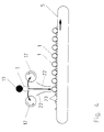
- the Device a storage station 3 for the tubes 2, which can be seen in Fig. 1 above.
- one Processing station 4 provided, in particular in the 2 and 3 is shown.
- the Device a transport device 5 for removing the completed cylinder tube sections 1, over which the Cylinder tube sections 1 of further processing be fed.
- a laser processing head 6 provided, the laser itself either in immediate vicinity of the processing station 4 or can also be arranged centrally, in which case the Laser beam via appropriate deflecting mirror Processing station 4 is performed.
- the device also has one Separating device 7, which ensures is that only one tube 2 at a time Processing station 4 is passed.
- a storage memory 8 arranged, which essentially consists of an inclined plane exists, through which the tubes 2 for Sliding device 7 slide down.
- the storage station 3 immediately after a distributor roller 9, by the at least two processing stations 4 simultaneously can be loaded with tubes 2. Basically there is of course also the possibility of more Processing stations 4 from a distribution roller 9 supply.
- the storage station 3 is funnel-shaped in detail trained and for loading with tubes 2 in one Operating position can be moved, which is not in the drawing is shown in more detail. Through the storage 8 there is sufficient time to reload the storage station 3, without interruptions in the production process arise.
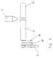
- the processing station 4 is exposed in detail a rotation and feed device 10 for the pipes and from a receiving and discharge device 11 for the Cylinder tube sections together, as shown in FIG. 2 and 3 emerges.
- the rotation and Feed device 10 two axially parallel to each other running, with a small mutual distance from each other arranged and driven in the same direction Support rollers 12 for the tubes 2, above which Pressure rollers 13 for the tube 2 are arranged.
- This Pressure rollers 13 are opposed by pneumatic cylinders 14 the tube 2 is deliverable and together on one Swivel beam 15 arranged transversely to the axis of the Support rollers 12 is adjustable. This means that Possibility to press the pressure rollers 13 over the To slightly lift the swivel bar 15 from the tube 2, if this is in the axial direction for receiving and Removal unit 11 is to be advanced axially.
- the pneumatic cylinders 14 are a Pressure control controlled, so that the setting of the required contact pressure can be made.
- the support rollers 12 have a surface provided with sufficiently high static friction compared to glass, so that on the one hand a rotary drive of the tubes 2 on the other hand, damage to the pipe surface excluded are.
- the rotation and feed device 10 a transport carriage 16 for the axial feed of the Pipes 2, with increasing displacement of the Transport carriage 16 for receiving and Discharge device 11 the pressure rollers 13 over the pneumatic cylinder 14 are lifted off so that the Transport sled 16 underneath them without interference can move.
- the receiving and discharging device 11 has one of two Support rollers 17 formed pliers roller, in particular in 7 is clearly visible.
- the two support rollers 17 also run parallel to each other and are - in their machining position - with little mutual Spaced from each other.
- the support rollers too become in the same direction and also in sync with the Support rollers 12 driven by rotation.
- Each of the two support rollers 17 is on one one-armed lever 18 arranged at the end. With your at the other end, the control levers 18 are coaxial with the one Support rollers 17 driving gear 19 pivotable stored.
- the receiving and discharge unit 11 has one of the 2 and 3 to see stop roller 20, which in its Adaptable to the diameter of the cylinder tube section 1 and is axially alignable to this. This is one uniform length of the manufactured Cylinder tube sections 1 guaranteed.
- the receiving and discharge unit 11 also has one Pressure roller 13 on a pneumatic cylinder against the tube 2 or the cylinder tube section 1 is deliverable.
- This pneumatic cylinder is also also on the adjustable swivel bar 15 arranged so that to feed the tube 2 this too Pressure roller 13 is in the raised position.
- one or more the pressure rollers 13 in a compared to Support rollers 12 be adjustable oblique orientation. This creates an additional feed force on the Tube 2 or the cylinder tube section 1 applied.
- the transition area between the rotation and Feed device 10 and the receiving and Removal device 11 can not in the drawing Suction device for glass sublimate shown in more detail be provided.
- Next can be in the same area also arranged optical sensor, not shown be used to determine the gap between the pipe 2 and serves the cylinder tube section 1.
- the determination of the Gap can take into account the process parameters be of importance when remelting the end faces.
- a form roller 21 for mechanical influencing of the remelting of the End faces forming bead may be provided in the Fig. 3 is only indicated schematically.
- the receiving and discharge device 11th provided with spring plates 22 below the pliers roller, as can be seen from FIG. 4. These spring plates 22 direct the separated cylinder tube sections 1 in prismatic receptacles 23 of the transport device 5, which further ensures that no excessive Heat drain from the still heated Cylinder tube sections 1 can take place. This will the risk of the occurrence of additional mechanical Tensions in the cylinder tube sections 1 avoided.
- the tubes 2 are made of Storage station 3 first isolated and then transferred individually to the processing station 4, the tubes 2 for successive separation of the Cylinder tube sections 1 held axially and be rotated about their longitudinal axis.
- the cylinder tube sections 1 themselves are separated by a laser 6 only indicated in the drawing.
- the cylinder tube section 1 move axially to distance 2 from the pipe. Then the opposite end faces of the tube 2 and the Melted cylinder tube section 1 into a bead, where the geometrical shape of the bead through corresponding to the diameter of the workpiece (tube 2 and cylinder tube section 1) coordinated rotation and by using the centrifugal forces that occur is also designed.
- the form roller 22 carries independently of which also to the design of the bead. The Machining the end faces of the tube 2 and the Cylinder tube section 1 can either simultaneously or also take place sequentially.
- the Processing stations operated in pairs, two Machining stations from a common Stocking station. Can continue several, preferably two such pairs Processing stations may be provided, the Laser processing alternately to the Processing stations are done and the filing of Cylinder tube sections 1 and the feeding of the Glass tube 2 always takes place when the Laser processing process on the others Processing stations expires.
Landscapes
- Chemical & Material Sciences (AREA)
- Engineering & Computer Science (AREA)
- Materials Engineering (AREA)
- Organic Chemistry (AREA)
- Physics & Mathematics (AREA)
- Health & Medical Sciences (AREA)
- Optics & Photonics (AREA)
- Toxicology (AREA)
- Laser Beam Processing (AREA)
- Re-Forming, After-Treatment, Cutting And Transporting Of Glass Products (AREA)
- Manufacture, Treatment Of Glass Fibers (AREA)
Priority Applications (1)
| Application Number | Priority Date | Filing Date | Title |
|---|---|---|---|
| DK99124694T DK1026128T3 (da) | 1999-02-06 | 1999-12-11 | Fremgangsmåde til fremstilling af cylindriske rörstykker, fortrinsvis fra glasrör, og et apparat til udövelse deraf |
Applications Claiming Priority (2)
| Application Number | Priority Date | Filing Date | Title |
|---|---|---|---|
| DE1999104978 DE19904978A1 (de) | 1999-02-06 | 1999-02-06 | Verfahren zur Herstellung von Zylinderrohrabschnitten aus vorzugsweise aus Glas bestehenden Rohren und Vorrichtung zur Durchführung des Verfahrens |
| DE19904978 | 1999-02-06 |
Publications (3)
| Publication Number | Publication Date |
|---|---|
| EP1026128A2 true EP1026128A2 (fr) | 2000-08-09 |
| EP1026128A3 EP1026128A3 (fr) | 2001-01-10 |
| EP1026128B1 EP1026128B1 (fr) | 2004-08-18 |
Family
ID=7896729
Family Applications (1)
| Application Number | Title | Priority Date | Filing Date |
|---|---|---|---|
| EP99124694A Expired - Lifetime EP1026128B1 (fr) | 1999-02-06 | 1999-12-11 | Procédé de fabrication de tubes cylindriques coupés de préférence à partir de tubes en verre et appareil pour appliquer ledit procédé |
Country Status (9)
| Country | Link |
|---|---|
| US (1) | US6310318B1 (fr) |
| EP (1) | EP1026128B1 (fr) |
| JP (1) | JP2000226221A (fr) |
| AT (1) | ATE273935T1 (fr) |
| CA (1) | CA2298204C (fr) |
| DE (2) | DE19904978A1 (fr) |
| DK (1) | DK1026128T3 (fr) |
| ES (1) | ES2222654T3 (fr) |
| PT (1) | PT1026128E (fr) |
Cited By (2)
| Publication number | Priority date | Publication date | Assignee | Title |
|---|---|---|---|---|
| WO2002026644A1 (fr) * | 2000-09-27 | 2002-04-04 | Schott Glas | Procede et dispositif pour decouper des tubes de verre |
| US9028198B2 (en) | 2011-02-25 | 2015-05-12 | Trumpf Werkzeugmaschinen Gmbh + Co. Kg | Workpiece handling systems and related devices and methods |
Families Citing this family (11)
| Publication number | Priority date | Publication date | Assignee | Title |
|---|---|---|---|---|
| US6783088B1 (en) | 2002-02-27 | 2004-08-31 | James Murray Gillis | Method of producing glass and of using glass in cutting materials |
| KR101241119B1 (ko) * | 2006-12-20 | 2013-03-11 | 박근노 | 레이저 커팅 장치 |
| JP5516994B2 (ja) * | 2011-01-14 | 2014-06-11 | 日本電気硝子株式会社 | リードスイッチ用ガラス管 |
| JP6757491B2 (ja) * | 2015-10-20 | 2020-09-23 | 日本電気硝子株式会社 | 管ガラスの切断方法及び切断装置、並びに管ガラス製品の製造方法 |
| JP2017081804A (ja) * | 2015-10-30 | 2017-05-18 | 日本電気硝子株式会社 | 管ガラスの切断方法及び切断装置、並びに管ガラス製品の製造方法 |
| US10968133B2 (en) | 2017-11-30 | 2021-04-06 | Corning Incorporated | Methods for minimizing SHR in glass articles by producing a gas flow during pharmaceutical part converting |
| US11186513B2 (en) | 2017-11-30 | 2021-11-30 | Corning Incorporated | Systems and methods for minimizing SHR from pharmaceutical part converting using negative pressure evacuation |
| US11339079B2 (en) | 2017-11-30 | 2022-05-24 | Corning Incorporated | Systems and methods for minimizing SHR from pharmaceutical part converting using pulsed ejection |
| US11420893B2 (en) | 2017-11-30 | 2022-08-23 | Corning Incorporated | Systems and methods for minimizing SHR from piercing during pharmaceutical part converting using a gas flow |
| CN117756394A (zh) | 2018-09-03 | 2024-03-26 | 尼普洛株式会社 | 从玻璃管分离中空玻璃体的方法以及用于制造容器的方法和系统 |
| DE102020114903A1 (de) * | 2020-06-04 | 2021-12-09 | Gerresheimer Bünde Gmbh | Verfahren und Anlage zum Herstellen eines Glasbehältnisses sowie Glasbehältnis |
Family Cites Families (21)
| Publication number | Priority date | Publication date | Assignee | Title |
|---|---|---|---|---|
| US1343179A (en) * | 1920-06-08 | macnichol | ||
| DE1127042B (de) * | 1959-09-14 | 1962-04-05 | Rota Patent A G | Verfahren und Einrichtung zur Herstellung von fremdkoerperfreien Glasgefaessen, insbesondere Ampullen, Injektionsflaschen u. dgl., aus Glasroehren |
| GB1360232A (en) * | 1971-03-22 | 1974-07-17 | Pilkington Brothers Ltd | Methods of and apparatus for cutting glass |
| US3770173A (en) * | 1972-09-11 | 1973-11-06 | Billco Mfg Inc | Apparatus for automatically breaking out a scored glass bracket |
| GB1484724A (en) * | 1974-05-21 | 1977-09-01 | Jobling & Co James A | Cutting glass tubing |
| US4225070A (en) * | 1979-05-09 | 1980-09-30 | Ppg Industries, Inc. | Method of simultaneously opening two scores transverse to one another |
| US4248369A (en) * | 1979-08-02 | 1981-02-03 | General Electric Company | Laser cutting of ceramic tubing |
| US4351459A (en) * | 1980-11-26 | 1982-09-28 | Huey Miin Perng | Automatic glass tube cutter |
| US4467168A (en) * | 1981-04-01 | 1984-08-21 | Creative Glassworks International | Method of cutting glass with a laser and an article made therewith |
| US4609807A (en) * | 1984-12-28 | 1986-09-02 | Midwest Laser Systems, Inc. | Apparatus and methods for laser severing metal tubular stock |
| JPS61229487A (ja) * | 1985-04-03 | 1986-10-13 | Sasaki Glass Kk | レ−ザビ−ムによるガラス切断方法 |
| US4931615A (en) * | 1988-12-02 | 1990-06-05 | General Electric Company | Apparatus for machining intricate feature cuts in thin walled tubular parts |
| GB2234202B (en) * | 1989-06-09 | 1993-03-24 | Molins Plc | Composite panel assembly |
| US5141428A (en) * | 1990-03-16 | 1992-08-25 | Philip Morris Incorporated | Apparatus for cutting thin-walled tubes |
| AT403688B (de) * | 1992-11-02 | 1998-04-27 | Lisec Peter | Verfahren und vorrichtung zum schneiden von verbundglas |
| DE4444547C2 (de) * | 1994-12-14 | 1997-02-27 | Schott Rohrglas Gmbh | Verfahren zum wärmeweichen Trennen von dünnwandigen Glasrohren oder -platten |
| US5744778A (en) * | 1996-04-02 | 1998-04-28 | G&H Diversified Manufacturing, Inc. | Tube handling method and apparatus for cutting machine |
| DE19616327C2 (de) * | 1996-04-24 | 1999-07-22 | Schott Rohrglas Gmbh | Verfahren und Vorrichtung zum Trennen von dünnwandigen Glasrohren |
| US5942132A (en) * | 1996-06-11 | 1999-08-24 | Kawasaki Steel Corporation | Method of and apparatus for producing steel pipes |
| JPH11156576A (ja) * | 1997-11-28 | 1999-06-15 | Amada Co Ltd | レーザ加工機におけるパイプ切断方法およびその装置 |
| US6087624A (en) * | 1998-05-18 | 2000-07-11 | Lear Corporation | Programmable fiber chopper and method therefor |
-
1999
- 1999-02-06 DE DE1999104978 patent/DE19904978A1/de not_active Withdrawn
- 1999-12-11 DE DE59910275T patent/DE59910275D1/de not_active Expired - Fee Related
- 1999-12-11 DK DK99124694T patent/DK1026128T3/da active
- 1999-12-11 ES ES99124694T patent/ES2222654T3/es not_active Expired - Lifetime
- 1999-12-11 AT AT99124694T patent/ATE273935T1/de not_active IP Right Cessation
- 1999-12-11 EP EP99124694A patent/EP1026128B1/fr not_active Expired - Lifetime
- 1999-12-11 PT PT99124694T patent/PT1026128E/pt unknown
-
2000
- 2000-02-04 CA CA 2298204 patent/CA2298204C/fr not_active Expired - Fee Related
- 2000-02-07 US US09/499,239 patent/US6310318B1/en not_active Expired - Fee Related
- 2000-02-07 JP JP2000028724A patent/JP2000226221A/ja active Pending
Cited By (3)
| Publication number | Priority date | Publication date | Assignee | Title |
|---|---|---|---|---|
| WO2002026644A1 (fr) * | 2000-09-27 | 2002-04-04 | Schott Glas | Procede et dispositif pour decouper des tubes de verre |
| US9028198B2 (en) | 2011-02-25 | 2015-05-12 | Trumpf Werkzeugmaschinen Gmbh + Co. Kg | Workpiece handling systems and related devices and methods |
| US10023404B2 (en) | 2011-02-25 | 2018-07-17 | Trumpf Werkzeugmaschinen Gmbh + Co. Kg | Workpiece handling systems and related devices and methods |
Also Published As
| Publication number | Publication date |
|---|---|
| CA2298204C (fr) | 2004-01-27 |
| EP1026128B1 (fr) | 2004-08-18 |
| US6310318B1 (en) | 2001-10-30 |
| JP2000226221A (ja) | 2000-08-15 |
| DE19904978A1 (de) | 2000-08-10 |
| ATE273935T1 (de) | 2004-09-15 |
| DK1026128T3 (da) | 2004-11-22 |
| DE59910275D1 (de) | 2004-09-23 |
| CA2298204A1 (fr) | 2000-08-06 |
| ES2222654T3 (es) | 2005-02-01 |
| PT1026128E (pt) | 2004-11-30 |
| EP1026128A3 (fr) | 2001-01-10 |
Similar Documents
| Publication | Publication Date | Title |
|---|---|---|
| EP2492041B1 (fr) | Dispositif avec un dispositif d'usinage de tuyau ; Méthode de déchargement d'un tuyau utilisant un tel dispositif | |
| EP2845714B1 (fr) | Dispositif et procédé destinés au chauffage d'ébauches en plastique avec montage ou démontage simultané d'éléments de support et d'éléments de masquage | |
| EP1026128B1 (fr) | Procédé de fabrication de tubes cylindriques coupés de préférence à partir de tubes en verre et appareil pour appliquer ledit procédé | |
| EP0475047B1 (fr) | Appareil et procédé pour transformer le bout chauffé d'un tube en verre et application dudit appareil dans une machine pour fabriquer des petites bouteilles | |
| EP2611554A1 (fr) | Tête de prise pour dispositifs de prise pour la manipulation de pièces allongées, dispositif d'amenée et d'évacuation de pièces allongées en direction et hors d'une machine d'usinage, et procédé de redressage par cintrage de pièces allongées | |
| WO2012028296A1 (fr) | Machine de redressage et de cintrage d'une pièce allongée, dispositif d'amenée et d'évacuation à cet effet, et procédé de redressage par cintrage de pièces allongées | |
| DE69712429T2 (de) | Verfahren zum Schweissen von Knüppeln die aus einem Ofen herausgenommen sind, und Walzanlage zur Anwendung dieses Verfahrens | |
| EP1128925B1 (fr) | Procede et dispositif pour souder des tubes | |
| DE69007033T2 (de) | Warmwalzverfahren für nahtlose Rohre mit vorausgehender Verringerung des Durchmessers von Halbzeug. | |
| EP4119327B1 (fr) | Dispositif de tri et rail d'alimentation pour préformes en matière plastique | |
| EP3103616A1 (fr) | Dispositif et procédé destinés à la fabrication de récipients en matière plastique ovales | |
| DE3533119C2 (fr) | ||
| EP3456443A1 (fr) | Dispositif d'alimentation en matériau en barres | |
| DE69129077T2 (de) | Verfahren und vorrichtung zum schneiden von rohren, in welchem die rohre mittels einer rotierenden festhaltplatte in schneidposition gebracht werden | |
| AT407348B (de) | Verfahren zum herstellen eines warmgewalzten produktes und anlage zur durchführung des verfahrens | |
| EP4028183B1 (fr) | Dispositif et procédé de laminage par étirage | |
| DE102008028348B4 (de) | Vorrichtung zum Führen von rotierenden Dornstangen und Hohlblöcken im Bereich von Schrägwalzwerken | |
| DE3227448A1 (de) | Vorrichtung zum vorerhitzen der enden von angestauchten stahlrohren | |
| EP1345715B1 (fr) | Presse a forger dotee d'un dispositif de reglage situe cote matrice | |
| DE722778C (de) | Maschine zum Herstellen von Tablettenglaesern, Ampullen und anderen Glashohlkoerpern | |
| DE60000888T2 (de) | Ein Verfahren und eine Vorrichtung zur kontinuierlichen Herstellung von Förderschnecken für Archimedesförderschnecken | |
| DE69024059T2 (de) | Vorrichtung und verfahren zum vorlochen von blöcken. | |
| DE256817C (fr) | ||
| DE19513610C2 (de) | Verfahren und Vorrichtung zur Förderung von Werkstücken | |
| EP1419840A1 (fr) | Dispositif d'usinage, notamment de rabotage, des bords d'un matériel en forme de bande et procédé de soudage de laser |
Legal Events
| Date | Code | Title | Description |
|---|---|---|---|
| PUAI | Public reference made under article 153(3) epc to a published international application that has entered the european phase |
Free format text: ORIGINAL CODE: 0009012 |
|
| AK | Designated contracting states |
Kind code of ref document: A2 Designated state(s): AT BE CH CY DE DK ES FI FR GB GR IE IT LI LU MC NL PT SE |
|
| AX | Request for extension of the european patent |
Free format text: AL;LT;LV;MK;RO;SI |
|
| PUAL | Search report despatched |
Free format text: ORIGINAL CODE: 0009013 |
|
| AK | Designated contracting states |
Kind code of ref document: A3 Designated state(s): AT BE CH CY DE DK ES FI FR GB GR IE IT LI LU MC NL PT SE |
|
| AX | Request for extension of the european patent |
Free format text: AL;LT;LV;MK;RO;SI |
|
| 17P | Request for examination filed |
Effective date: 20010127 |
|
| AKX | Designation fees paid |
Free format text: AT BE CH CY DE DK ES FI FR GB GR IE IT LI LU MC NL PT SE |
|
| 17Q | First examination report despatched |
Effective date: 20030228 |
|
| GRAP | Despatch of communication of intention to grant a patent |
Free format text: ORIGINAL CODE: EPIDOSNIGR1 |
|
| GRAS | Grant fee paid |
Free format text: ORIGINAL CODE: EPIDOSNIGR3 |
|
| GRAA | (expected) grant |
Free format text: ORIGINAL CODE: 0009210 |
|
| AK | Designated contracting states |
Kind code of ref document: B1 Designated state(s): AT BE CH CY DE DK ES FI FR GB GR IE IT LI LU MC NL PT SE |
|
| PG25 | Lapsed in a contracting state [announced via postgrant information from national office to epo] |
Ref country code: FI Free format text: LAPSE BECAUSE OF FAILURE TO SUBMIT A TRANSLATION OF THE DESCRIPTION OR TO PAY THE FEE WITHIN THE PRESCRIBED TIME-LIMIT Effective date: 20040818 Ref country code: CY Free format text: LAPSE BECAUSE OF FAILURE TO SUBMIT A TRANSLATION OF THE DESCRIPTION OR TO PAY THE FEE WITHIN THE PRESCRIBED TIME-LIMIT Effective date: 20040818 |
|
| REG | Reference to a national code |
Ref country code: GB Ref legal event code: FG4D Free format text: NOT ENGLISH |
|
| REG | Reference to a national code |
Ref country code: CH Ref legal event code: EP |
|
| GBT | Gb: translation of ep patent filed (gb section 77(6)(a)/1977) |
Effective date: 20040818 |
|
| REG | Reference to a national code |
Ref country code: CH Ref legal event code: NV Representative=s name: ISLER & PEDRAZZINI AG |
|
| REG | Reference to a national code |
Ref country code: IE Ref legal event code: FG4D Free format text: GERMAN |
|
| REF | Corresponds to: |
Ref document number: 59910275 Country of ref document: DE Date of ref document: 20040923 Kind code of ref document: P |
|
| REG | Reference to a national code |
Ref country code: GR Ref legal event code: EP Ref document number: 20040403035 Country of ref document: GR |
|
| PGFP | Annual fee paid to national office [announced via postgrant information from national office to epo] |
Ref country code: SE Payment date: 20041118 Year of fee payment: 6 |
|
| REG | Reference to a national code |
Ref country code: DK Ref legal event code: T3 |
|
| REG | Reference to a national code |
Ref country code: SE Ref legal event code: TRGR |
|
| REG | Reference to a national code |
Ref country code: PT Ref legal event code: SC4A Free format text: AVAILABILITY OF NATIONAL TRANSLATION Effective date: 20040924 |
|
| PGFP | Annual fee paid to national office [announced via postgrant information from national office to epo] |
Ref country code: DK Payment date: 20041202 Year of fee payment: 6 |
|
| PGFP | Annual fee paid to national office [announced via postgrant information from national office to epo] |
Ref country code: CH Payment date: 20041215 Year of fee payment: 6 |
|
| PGFP | Annual fee paid to national office [announced via postgrant information from national office to epo] |
Ref country code: BE Payment date: 20041222 Year of fee payment: 6 |
|
| PG25 | Lapsed in a contracting state [announced via postgrant information from national office to epo] |
Ref country code: MC Free format text: LAPSE BECAUSE OF NON-PAYMENT OF DUE FEES Effective date: 20041231 |
|
| PGFP | Annual fee paid to national office [announced via postgrant information from national office to epo] |
Ref country code: NL Payment date: 20041231 Year of fee payment: 6 |
|
| PGFP | Annual fee paid to national office [announced via postgrant information from national office to epo] |
Ref country code: AT Payment date: 20050131 Year of fee payment: 6 |
|
| REG | Reference to a national code |
Ref country code: ES Ref legal event code: FG2A Ref document number: 2222654 Country of ref document: ES Kind code of ref document: T3 |
|
| ET | Fr: translation filed | ||
| PLBE | No opposition filed within time limit |
Free format text: ORIGINAL CODE: 0009261 |
|
| STAA | Information on the status of an ep patent application or granted ep patent |
Free format text: STATUS: NO OPPOSITION FILED WITHIN TIME LIMIT |
|
| 26N | No opposition filed |
Effective date: 20050519 |
|
| PGFP | Annual fee paid to national office [announced via postgrant information from national office to epo] |
Ref country code: FR Payment date: 20050824 Year of fee payment: 7 |
|
| PGFP | Annual fee paid to national office [announced via postgrant information from national office to epo] |
Ref country code: PT Payment date: 20050830 Year of fee payment: 7 |
|
| PGFP | Annual fee paid to national office [announced via postgrant information from national office to epo] |
Ref country code: GR Payment date: 20051020 Year of fee payment: 7 |
|
| PGFP | Annual fee paid to national office [announced via postgrant information from national office to epo] |
Ref country code: LU Payment date: 20051028 Year of fee payment: 7 |
|
| PGFP | Annual fee paid to national office [announced via postgrant information from national office to epo] |
Ref country code: ES Payment date: 20051118 Year of fee payment: 7 |
|
| PGFP | Annual fee paid to national office [announced via postgrant information from national office to epo] |
Ref country code: GB Payment date: 20051124 Year of fee payment: 7 |
|
| PGFP | Annual fee paid to national office [announced via postgrant information from national office to epo] |
Ref country code: IE Payment date: 20051129 Year of fee payment: 7 |
|
| PG25 | Lapsed in a contracting state [announced via postgrant information from national office to epo] |
Ref country code: AT Free format text: LAPSE BECAUSE OF NON-PAYMENT OF DUE FEES Effective date: 20051211 |
|
| PG25 | Lapsed in a contracting state [announced via postgrant information from national office to epo] |
Ref country code: SE Free format text: LAPSE BECAUSE OF NON-PAYMENT OF DUE FEES Effective date: 20051212 |
|
| PG25 | Lapsed in a contracting state [announced via postgrant information from national office to epo] |
Ref country code: LI Free format text: LAPSE BECAUSE OF NON-PAYMENT OF DUE FEES Effective date: 20051231 Ref country code: CH Free format text: LAPSE BECAUSE OF NON-PAYMENT OF DUE FEES Effective date: 20051231 Ref country code: BE Free format text: LAPSE BECAUSE OF NON-PAYMENT OF DUE FEES Effective date: 20051231 |
|
| PG25 | Lapsed in a contracting state [announced via postgrant information from national office to epo] |
Ref country code: DK Free format text: LAPSE BECAUSE OF NON-PAYMENT OF DUE FEES Effective date: 20060102 |
|
| PGFP | Annual fee paid to national office [announced via postgrant information from national office to epo] |
Ref country code: DE Payment date: 20060213 Year of fee payment: 7 |
|
| PG25 | Lapsed in a contracting state [announced via postgrant information from national office to epo] |
Ref country code: NL Free format text: LAPSE BECAUSE OF NON-PAYMENT OF DUE FEES Effective date: 20060701 |
|
| REG | Reference to a national code |
Ref country code: DK Ref legal event code: EBP |
|
| REG | Reference to a national code |
Ref country code: CH Ref legal event code: PL |
|
| EUG | Se: european patent has lapsed | ||
| NLV4 | Nl: lapsed or anulled due to non-payment of the annual fee |
Effective date: 20060701 |
|
| PG25 | Lapsed in a contracting state [announced via postgrant information from national office to epo] |
Ref country code: IE Free format text: LAPSE BECAUSE OF NON-PAYMENT OF DUE FEES Effective date: 20061211 |
|
| PGFP | Annual fee paid to national office [announced via postgrant information from national office to epo] |
Ref country code: IT Payment date: 20061231 Year of fee payment: 8 |
|
| PG25 | Lapsed in a contracting state [announced via postgrant information from national office to epo] |
Ref country code: PT Free format text: LAPSE BECAUSE OF NON-PAYMENT OF DUE FEES Effective date: 20070611 |
|
| REG | Reference to a national code |
Ref country code: PT Ref legal event code: MM4A Free format text: LAPSE DUE TO NON-PAYMENT OF FEES Effective date: 20070611 |
|
| PG25 | Lapsed in a contracting state [announced via postgrant information from national office to epo] |
Ref country code: DE Free format text: LAPSE BECAUSE OF NON-PAYMENT OF DUE FEES Effective date: 20070703 |
|
| GBPC | Gb: european patent ceased through non-payment of renewal fee |
Effective date: 20061211 |
|
| REG | Reference to a national code |
Ref country code: IE Ref legal event code: MM4A |
|
| REG | Reference to a national code |
Ref country code: FR Ref legal event code: ST Effective date: 20070831 |
|
| PG25 | Lapsed in a contracting state [announced via postgrant information from national office to epo] |
Ref country code: GB Free format text: LAPSE BECAUSE OF NON-PAYMENT OF DUE FEES Effective date: 20061211 |
|
| BERE | Be: lapsed |
Owner name: ARZNEIMITTEL G.M.B.H. APOTHEKER *VETTER & CO. RAVE Effective date: 20051231 |
|
| REG | Reference to a national code |
Ref country code: ES Ref legal event code: FD2A Effective date: 20061212 |
|
| PG25 | Lapsed in a contracting state [announced via postgrant information from national office to epo] |
Ref country code: FR Free format text: LAPSE BECAUSE OF NON-PAYMENT OF DUE FEES Effective date: 20070102 Ref country code: ES Free format text: LAPSE BECAUSE OF NON-PAYMENT OF DUE FEES Effective date: 20061212 |
|
| PG25 | Lapsed in a contracting state [announced via postgrant information from national office to epo] |
Ref country code: LU Free format text: LAPSE BECAUSE OF NON-PAYMENT OF DUE FEES Effective date: 20061211 |
|
| PG25 | Lapsed in a contracting state [announced via postgrant information from national office to epo] |
Ref country code: GR Free format text: LAPSE BECAUSE OF NON-PAYMENT OF DUE FEES Effective date: 20070704 |
|
| PG25 | Lapsed in a contracting state [announced via postgrant information from national office to epo] |
Ref country code: IT Free format text: LAPSE BECAUSE OF NON-PAYMENT OF DUE FEES Effective date: 20071211 |