EP1026332A1 - Bouche d'écoulement avec siphon - Google Patents
Bouche d'écoulement avec siphon Download PDFInfo
- Publication number
- EP1026332A1 EP1026332A1 EP99123811A EP99123811A EP1026332A1 EP 1026332 A1 EP1026332 A1 EP 1026332A1 EP 99123811 A EP99123811 A EP 99123811A EP 99123811 A EP99123811 A EP 99123811A EP 1026332 A1 EP1026332 A1 EP 1026332A1
- Authority
- EP
- European Patent Office
- Prior art keywords
- siphon
- valve seat
- valve
- housing
- inlet
- Prior art date
- Legal status (The legal status is an assumption and is not a legal conclusion. Google has not performed a legal analysis and makes no representation as to the accuracy of the status listed.)
- Withdrawn
Links
- 241001465754 Metazoa Species 0.000 claims description 10
- 239000007788 liquid Substances 0.000 claims description 6
- 230000001681 protective effect Effects 0.000 claims description 6
- 238000003780 insertion Methods 0.000 claims description 2
- 230000037431 insertion Effects 0.000 claims description 2
- 238000009434 installation Methods 0.000 claims description 2
- XLYOFNOQVPJJNP-UHFFFAOYSA-N water Substances O XLYOFNOQVPJJNP-UHFFFAOYSA-N 0.000 abstract description 4
- 230000000903 blocking effect Effects 0.000 abstract 1
- 230000000284 resting effect Effects 0.000 abstract 1
- 239000002351 wastewater Substances 0.000 abstract 1
- 238000005192 partition Methods 0.000 description 3
- 238000013461 design Methods 0.000 description 2
- 238000011161 development Methods 0.000 description 2
- 239000010865 sewage Substances 0.000 description 2
- 238000012549 training Methods 0.000 description 2
- 230000003247 decreasing effect Effects 0.000 description 1
- 238000012423 maintenance Methods 0.000 description 1
- 230000000630 rising effect Effects 0.000 description 1
- 238000007789 sealing Methods 0.000 description 1
Images

Classifications
-
- E—FIXED CONSTRUCTIONS
- E03—WATER SUPPLY; SEWERAGE
- E03F—SEWERS; CESSPOOLS
- E03F5/00—Sewerage structures
- E03F5/04—Gullies inlets, road sinks, floor drains with or without odour seals or sediment traps
- E03F5/042—Arrangements of means against overflow of water, backing-up from the drain
Definitions
- the invention relates to an overflow with a siphon, which is a siphon housing with an open top a coaxial valve seat inlet fitting and in the case below the valve seat in the siphon housing one trained as a swimmer, in the open position sitting on a support, inadmissible strongly rising liquid level sealing against the Valve seat movable valve ball is arranged and the to connect to a sewer one with a light one Inclined outlet nozzle, in particular for installation in a cistern for rainwater use.
- a siphon which is a siphon housing with an open top a coaxial valve seat inlet fitting and in the case below the valve seat in the siphon housing one trained as a swimmer, in the open position sitting on a support, inadmissible strongly rising liquid level sealing against the Valve seat movable valve ball is arranged and the to connect to a sewer one with a light one Inclined outlet nozzle, in particular for installation in a cistern for rainwater use.
- An overflow of the above type is the subject of DE 28 09 825.
- the siphon prevents such an overflow, that there is an air connection from the sewer to the Component exists to which the siphon is connected, and this can lead to an unpleasant smell.
- the valve seat forms a backflow valve with the float. This is for example in one in one Cistern arranged overflow required so backwater in the sewer system, no sewage from the sewer system can get into the cistern.
- the invention is based on the problem of an overflow of the type mentioned in the introduction so that incrustations on the float without complex maintenance work can be avoided.
- valve ball is cleaned particularly well if according to another development of the invention of the inlet nozzle one decreased in height to one side Has inlet edge and if the inlet nozzle to the side with reduced height of the leading edge in relation to the Valve ball is offset. Meet through this training small overflow quantities only at a large distance to the center of the valve ball on this, causing even small overflow quantities are already able to To cause rotation of the valve ball provided the valve ball due to the water level in the cistern of their Support is lifted.
- valve ball is guided in one plane, so that it to close the valve seat only in this plane must move diagonally upwards and jamming of the valve ball in the valve housing in the open position of the backflow valve cannot occur if according to another Development of the invention, the support by two parallel to each other, leading obliquely into the siphon housing, rib-like support ramps is formed.
- the siphon housing a detachably fastened on an upper wall surface Cover that has on the inside with a small animal protection grille leading in front of the outlet is provided.
- the small animal protective grille is particularly simple in design if designed by several, from the lid Tines pointing obliquely downwards towards the outlet nozzle is formed and the cover is a positioning lock for insertion in only one defined orientation having. Such a positioning lock ensures that that the lid is only in that position can be closed, in which the tines actually the Block the outlet nozzle for small animals.
- the siphon inside the cistern is only held by having its outlet port is pushed into a sewage pipe and that it is against there is a wall of the cistern. Due to the weight of the Siphon incoming liquid creates a tilting moment through which the siphon tends to come out of the sewer pipe slip out. The siphon hangs somewhat at an angle down, then this tendency is undesirably large.
- the overflow shown in Figure 1 has a cross section rectangular siphon housing 1 with a vertical aligned inlet nozzle 2 on its top and an outlet nozzle with a slight slope 3.
- the inlet connector 2 is coaxial with a seal 4 aligned, which forms a valve seat 5 against as a closing element for a backwater one as a float trained valve ball 6 is present.
- the valve ball 6 forms a backflow valve together with the valve seat 5.
- the valve ball is in the open position shown 6 against a rib-like support 7.
- the valve ball 6 is supported against a partition 8 of the Siphon case 1 starting from its top down leads and leaves only one passage 9 there.
- the Water entering the siphon therefore flows from the inlet connection 2 first past the valve ball 6 below, then through passage 9 and at the other Side of the partition 8 vertically upwards until it is the siphon housing 1 leaves via the outlet 3.
- the inlet connector 2 has a leading edge 10, which to the side of Support 7 drops.
- the leading edge 10 runs so weird.
- the valve ball 6 is in the open position in one to the inlet nozzle 2 and thus also to the valve seat 5 to the side offset position the inlet pipe 2 has its greatest height. This offset arrangement has the consequence that incoming Water off-center on the left as seen in the drawing Side of the valve ball 6 strikes and this constantly turns.
- a Lid 11 On the top of the siphon housing 1 is still a Lid 11 arranged, from which a small animal protective grille 12 protrudes obliquely downwards and thereby the outlet nozzle 3 blocked.
- a support member near the bottom of the siphon housing 1 13 On the side of the siphon housing 1 with the outlet connection 3 is a support member near the bottom of the siphon housing 1 13 provided.
- This consists of a on the siphon housing 1 molded receptacle 14, in which a pipe 15 is pushed.
- This tube 15 has one Length that the siphon housing 1 is aligned exactly vertically is when you put the outlet nozzle 3 in a not shown drain pipe and then pushes the siphon the pipe 15 abuts against a wall of the cistern.
- FIG. 2 shows that in the siphon housing 1 by two Impressions two parallel to each other Support ramps 16, 17 are formed, which in Figure 1 shown support 7 form for the valve ball 6.
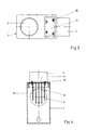
- FIG. 3 shows the inlet nozzle 2 and the cover 11 in the siphon housing 1.
- This cover 11 is fastened to the siphon housing 1 with screws 18, which is different on both sides of the lid 11 are spaced so that the cover 11 only in one single orientation can be mounted.
- the screws 18 therefore form a positioning device.
- Figure 4 shows that the small animal protective grille 12 consists of individual tines 19, which are different Have length and thus the cross section of the Cover the outlet connector. It can also be seen in 4 shows the cover 11 with the screws 18.
Landscapes
- Health & Medical Sciences (AREA)
- Life Sciences & Earth Sciences (AREA)
- Engineering & Computer Science (AREA)
- Hydrology & Water Resources (AREA)
- Public Health (AREA)
- Water Supply & Treatment (AREA)
- Float Valves (AREA)
- Check Valves (AREA)
Applications Claiming Priority (2)
| Application Number | Priority Date | Filing Date | Title |
|---|---|---|---|
| DE19904883 | 1999-02-06 | ||
| DE1999104883 DE19904883A1 (de) | 1999-02-06 | 1999-02-06 | Überlauf mit einem Siphon |
Publications (1)
| Publication Number | Publication Date |
|---|---|
| EP1026332A1 true EP1026332A1 (fr) | 2000-08-09 |
Family
ID=7896655
Family Applications (1)
| Application Number | Title | Priority Date | Filing Date |
|---|---|---|---|
| EP99123811A Withdrawn EP1026332A1 (fr) | 1999-02-06 | 1999-12-01 | Bouche d'écoulement avec siphon |
Country Status (2)
| Country | Link |
|---|---|
| EP (1) | EP1026332A1 (fr) |
| DE (2) | DE19904883A1 (fr) |
Cited By (2)
| Publication number | Priority date | Publication date | Assignee | Title |
|---|---|---|---|---|
| US20110272052A1 (en) * | 2010-05-05 | 2011-11-10 | Niels Arne Lauridsen | Rodent Guard |
| RU232172U1 (ru) * | 2024-11-28 | 2025-02-27 | Сергей Александрович Пухов | Сифон для кондиционера |
Families Citing this family (1)
| Publication number | Priority date | Publication date | Assignee | Title |
|---|---|---|---|---|
| DE20303259U1 (de) | 2003-02-28 | 2003-05-08 | REHAU AG + Co., 95111 Rehau | Regenwasserzisterne mit Flüssigkeitsniveau-Regulierung |
Citations (5)
| Publication number | Priority date | Publication date | Assignee | Title |
|---|---|---|---|---|
| US1469790A (en) * | 1921-05-02 | 1923-10-09 | Hipolit H Hysko | Bell-trap floor drain |
| DE1245873B (de) * | 1957-12-03 | 1967-07-27 | Alex Hering | Vorrichtung zum Absperren von Abwasserleitungen gegen das Eindringen von Ratten |
| FR1554150A (fr) * | 1967-01-31 | 1969-01-17 | ||
| DE2809825B1 (de) | 1978-03-07 | 1979-09-27 | Passavant Werke | Rueckstauverschluss fuer Abwasserleitungen |
| DE4033957A1 (de) * | 1990-10-25 | 1992-05-07 | Passavant Werke | Rueckstauverschluss |
Family Cites Families (5)
| Publication number | Priority date | Publication date | Assignee | Title |
|---|---|---|---|---|
| DE3002180A1 (de) * | 1980-01-22 | 1981-09-10 | Passavant-Werke Michelbacher Hütte, 6209 Aarbergen | Rueckstauverschluss fuer entwaesserungsleitungen |
| DE3046253C2 (de) * | 1980-12-08 | 1984-07-19 | Passavant-Werke AG & Co KG, 6209 Aarbergen | Rückstauverschluß |
| DE3243066C2 (de) * | 1982-11-22 | 1986-05-07 | Passavant-Werke AG & Co KG, 6209 Aarbergen | Sinkkasten mit Rückstau-Doppelverschluß |
| DE3536993A1 (de) * | 1985-10-17 | 1987-04-23 | Buderus Ag | Kellerablauf |
| DE29723263U1 (de) * | 1997-03-17 | 1998-10-08 | KAUTEX TEXTRON GmbH & Co. KG, 53229 Bonn | Sammelanlage für Wasser |
-
1999
- 1999-02-06 DE DE1999104883 patent/DE19904883A1/de not_active Withdrawn
- 1999-12-01 EP EP99123811A patent/EP1026332A1/fr not_active Withdrawn
- 1999-12-02 DE DE29921271U patent/DE29921271U1/de not_active Expired - Lifetime
Patent Citations (5)
| Publication number | Priority date | Publication date | Assignee | Title |
|---|---|---|---|---|
| US1469790A (en) * | 1921-05-02 | 1923-10-09 | Hipolit H Hysko | Bell-trap floor drain |
| DE1245873B (de) * | 1957-12-03 | 1967-07-27 | Alex Hering | Vorrichtung zum Absperren von Abwasserleitungen gegen das Eindringen von Ratten |
| FR1554150A (fr) * | 1967-01-31 | 1969-01-17 | ||
| DE2809825B1 (de) | 1978-03-07 | 1979-09-27 | Passavant Werke | Rueckstauverschluss fuer Abwasserleitungen |
| DE4033957A1 (de) * | 1990-10-25 | 1992-05-07 | Passavant Werke | Rueckstauverschluss |
Cited By (2)
| Publication number | Priority date | Publication date | Assignee | Title |
|---|---|---|---|---|
| US20110272052A1 (en) * | 2010-05-05 | 2011-11-10 | Niels Arne Lauridsen | Rodent Guard |
| RU232172U1 (ru) * | 2024-11-28 | 2025-02-27 | Сергей Александрович Пухов | Сифон для кондиционера |
Also Published As
| Publication number | Publication date |
|---|---|
| DE19904883A1 (de) | 2000-08-10 |
| DE29921271U1 (de) | 2000-03-30 |
Similar Documents
| Publication | Publication Date | Title |
|---|---|---|
| EP2045403B1 (fr) | Garniture d'ecoulement avec trop-plein intégré | |
| CH493706A (de) | Schwimmerventil | |
| DE9102152U1 (de) | Überlauf- und Ablaufgarnitur für sanitäre Apparate | |
| EP2250063A1 (fr) | Dispositif de ventilateur pour l'évacuation gravitationnelle de liquide avec la phase de surpression et de dépression | |
| EP0084082B1 (fr) | Vanne de remplissage d'un bac de chasse d'eau ou de réservoirs à fluides similaires | |
| DE69723143T2 (de) | Gerät zur Steuerung eines Ablaufvenmtils eines Spülkastens | |
| DE3907590A1 (de) | Spuelheber | |
| DE3310314C2 (fr) | ||
| DE602005000886T2 (de) | Siphon mit Rücklaufverhinderer | |
| DE69214775T2 (de) | Zwischenphase-Vakuumventil | |
| DE29921271U1 (de) | Überlauf mit einem Siphon | |
| DE2522425C3 (de) | Bodenablauf mit Genichverschluß für Abwasserbehälter | |
| EP2154300B1 (fr) | Station d'eaux usées | |
| DE2809825C2 (de) | Rückstauverschluß für Abwasserleitungen | |
| DE4416462A1 (de) | Entlüftungsvorrichtung für eine Toilette | |
| EP0565483B1 (fr) | Bassin dans une installation d'eaux usées | |
| DE60121660T2 (de) | Taktweise bearbeitendes Spülventil | |
| CH676264A5 (en) | Siphon for rain water sump | |
| DE3908092A1 (de) | Abwassersammelschacht mit tauchmotorpumpe | |
| DE3243066A1 (de) | Sinkkasten mit rueckstau-doppelverschluss | |
| DE4212708A1 (de) | Selbsttätig wirkende Hebervorrichtung | |
| DE10148959A1 (de) | Urinalvorrichtung, die an einer Wand befestigbar ist | |
| EP4424940A1 (fr) | Raccord de canalisation et kit de fabrication d'un tel raccord de canalisation | |
| CH674880A5 (en) | Siphon for rain water sump | |
| EP4520887A1 (fr) | Bouche d'égout avec piège à odeurs |
Legal Events
| Date | Code | Title | Description |
|---|---|---|---|
| PUAI | Public reference made under article 153(3) epc to a published international application that has entered the european phase |
Free format text: ORIGINAL CODE: 0009012 |
|
| AK | Designated contracting states |
Kind code of ref document: A1 Designated state(s): AT BE CH CY DE DK ES FI FR GB GR IE IT LI LU MC NL PT SE |
|
| AX | Request for extension of the european patent |
Free format text: AL;LT;LV;MK;RO;SI |
|
| 17P | Request for examination filed |
Effective date: 20010127 |
|
| AKX | Designation fees paid |
Free format text: AT BE CH CY DE DK ES FI FR GB GR IE IT LI LU MC NL PT SE |
|
| STAA | Information on the status of an ep patent application or granted ep patent |
Free format text: STATUS: THE APPLICATION IS DEEMED TO BE WITHDRAWN |
|
| 18D | Application deemed to be withdrawn |
Effective date: 20030701 |