EP1026357B1 - Profilé d'encadrement pour fenêtres ou portes en bois-métal - Google Patents
Profilé d'encadrement pour fenêtres ou portes en bois-métal Download PDFInfo
- Publication number
- EP1026357B1 EP1026357B1 EP00102366A EP00102366A EP1026357B1 EP 1026357 B1 EP1026357 B1 EP 1026357B1 EP 00102366 A EP00102366 A EP 00102366A EP 00102366 A EP00102366 A EP 00102366A EP 1026357 B1 EP1026357 B1 EP 1026357B1
- Authority
- EP
- European Patent Office
- Prior art keywords
- frame
- profile according
- frame profile
- strip
- profiled
- Prior art date
- Legal status (The legal status is an assumption and is not a legal conclusion. Google has not performed a legal analysis and makes no representation as to the accuracy of the status listed.)
- Expired - Lifetime
Links
- 229910000634 wood's metal Inorganic materials 0.000 title claims description 3
- 230000001681 protective effect Effects 0.000 claims abstract description 36
- 229910052782 aluminium Inorganic materials 0.000 claims abstract description 21
- XAGFODPZIPBFFR-UHFFFAOYSA-N aluminium Chemical compound [Al] XAGFODPZIPBFFR-UHFFFAOYSA-N 0.000 claims abstract description 19
- 239000000463 material Substances 0.000 claims description 8
- 238000010276 construction Methods 0.000 claims description 7
- 239000011324 bead Substances 0.000 claims description 5
- 239000004411 aluminium Substances 0.000 claims description 2
- 239000013013 elastic material Substances 0.000 claims description 2
- 238000003780 insertion Methods 0.000 claims description 2
- 230000037431 insertion Effects 0.000 claims description 2
- 230000000149 penetrating effect Effects 0.000 claims description 2
- 238000013022 venting Methods 0.000 claims 3
- 238000005253 cladding Methods 0.000 description 10
- 238000000034 method Methods 0.000 description 7
- 230000001965 increasing effect Effects 0.000 description 4
- 239000007788 liquid Substances 0.000 description 4
- XLYOFNOQVPJJNP-UHFFFAOYSA-N water Substances O XLYOFNOQVPJJNP-UHFFFAOYSA-N 0.000 description 4
- 239000000853 adhesive Substances 0.000 description 3
- 230000001070 adhesive effect Effects 0.000 description 3
- 238000007654 immersion Methods 0.000 description 3
- 238000007789 sealing Methods 0.000 description 3
- 239000002023 wood Substances 0.000 description 3
- 238000005452 bending Methods 0.000 description 2
- 230000000694 effects Effects 0.000 description 2
- 238000004519 manufacturing process Methods 0.000 description 2
- 238000003825 pressing Methods 0.000 description 2
- 238000009423 ventilation Methods 0.000 description 2
- 238000003466 welding Methods 0.000 description 2
- 238000004026 adhesive bonding Methods 0.000 description 1
- 230000005494 condensation Effects 0.000 description 1
- 238000009833 condensation Methods 0.000 description 1
- 230000001419 dependent effect Effects 0.000 description 1
- 238000009826 distribution Methods 0.000 description 1
- 239000011521 glass Substances 0.000 description 1
- 238000002347 injection Methods 0.000 description 1
- 239000007924 injection Substances 0.000 description 1
- 238000009413 insulation Methods 0.000 description 1
- 239000004033 plastic Substances 0.000 description 1
- 239000012261 resinous substance Substances 0.000 description 1
- 230000008719 thickening Effects 0.000 description 1
Images


Classifications
-
- E—FIXED CONSTRUCTIONS
- E06—DOORS, WINDOWS, SHUTTERS, OR ROLLER BLINDS IN GENERAL; LADDERS
- E06B—FIXED OR MOVABLE CLOSURES FOR OPENINGS IN BUILDINGS, VEHICLES, FENCES OR LIKE ENCLOSURES IN GENERAL, e.g. DOORS, WINDOWS, BLINDS, GATES
- E06B3/00—Window sashes, door leaves, or like elements for closing wall or like openings; Layout of fixed or moving closures, e.g. windows in wall or like openings; Features of rigidly-mounted outer frames relating to the mounting of wing frames
- E06B3/96—Corner joints or edge joints for windows, doors, or the like frames or wings
- E06B3/9624—Corner joints or edge joints for windows, doors, or the like frames or wings with means specially adapted for aligning the frontal surfaces of adjacent frame member ends
-
- E—FIXED CONSTRUCTIONS
- E06—DOORS, WINDOWS, SHUTTERS, OR ROLLER BLINDS IN GENERAL; LADDERS
- E06B—FIXED OR MOVABLE CLOSURES FOR OPENINGS IN BUILDINGS, VEHICLES, FENCES OR LIKE ENCLOSURES IN GENERAL, e.g. DOORS, WINDOWS, BLINDS, GATES
- E06B3/00—Window sashes, door leaves, or like elements for closing wall or like openings; Layout of fixed or moving closures, e.g. windows in wall or like openings; Features of rigidly-mounted outer frames relating to the mounting of wing frames
- E06B3/30—Coverings, e.g. protecting against weather, for decorative purposes
- E06B3/301—Coverings, e.g. protecting against weather, for decorative purposes consisting of prefabricated profiled members or glass
- E06B3/302—Covering wooden frames with metal or plastic profiled members
-
- E—FIXED CONSTRUCTIONS
- E06—DOORS, WINDOWS, SHUTTERS, OR ROLLER BLINDS IN GENERAL; LADDERS
- E06B—FIXED OR MOVABLE CLOSURES FOR OPENINGS IN BUILDINGS, VEHICLES, FENCES OR LIKE ENCLOSURES IN GENERAL, e.g. DOORS, WINDOWS, BLINDS, GATES
- E06B3/00—Window sashes, door leaves, or like elements for closing wall or like openings; Layout of fixed or moving closures, e.g. windows in wall or like openings; Features of rigidly-mounted outer frames relating to the mounting of wing frames
- E06B3/96—Corner joints or edge joints for windows, doors, or the like frames or wings
- E06B3/9612—Corner joints or edge joints for windows, doors, or the like frames or wings by filling in situ the hollow ends of the abutted frame members with a hardenable substance
-
- E—FIXED CONSTRUCTIONS
- E06—DOORS, WINDOWS, SHUTTERS, OR ROLLER BLINDS IN GENERAL; LADDERS
- E06B—FIXED OR MOVABLE CLOSURES FOR OPENINGS IN BUILDINGS, VEHICLES, FENCES OR LIKE ENCLOSURES IN GENERAL, e.g. DOORS, WINDOWS, BLINDS, GATES
- E06B3/00—Window sashes, door leaves, or like elements for closing wall or like openings; Layout of fixed or moving closures, e.g. windows in wall or like openings; Features of rigidly-mounted outer frames relating to the mounting of wing frames
- E06B3/96—Corner joints or edge joints for windows, doors, or the like frames or wings
- E06B3/984—Corner joints or edge joints for windows, doors, or the like frames or wings specially adapted for frame members of wood or other material worked in a similar way
- E06B3/9845—Mitre joints
-
- E—FIXED CONSTRUCTIONS
- E06—DOORS, WINDOWS, SHUTTERS, OR ROLLER BLINDS IN GENERAL; LADDERS
- E06B—FIXED OR MOVABLE CLOSURES FOR OPENINGS IN BUILDINGS, VEHICLES, FENCES OR LIKE ENCLOSURES IN GENERAL, e.g. DOORS, WINDOWS, BLINDS, GATES
- E06B7/00—Special arrangements or measures in connection with doors or windows
- E06B7/14—Measures for draining-off condensed water or water leaking-in frame members for draining off condensation water, throats at the bottom of a sash
Definitions
- the invention relates to frame profiles for the frame and the casement of wood-metal windows or - Doors, consisting of a load-bearing construction element serving wooden frame legs and a weather-side, made of drawn, thin-walled aluminum single or multi-layered protective cladding, which by interlocking interlocking connection elements is connected to the wooden frame leg.
- the attachment of the aluminum profile frame to the wooden frame takes place, for example, by so-called rotary holders as individual elements at certain intervals on the outside the wooden frame can be fixed with screws and which are profiled so that they are in a rotational position in mounting rails of the respective aluminum profile frame can be introduced. By rotating it accordingly about 90 ° then these rotary holders are in a rotating position brought in which they hold the aluminum profile.
- the aluminum profiles are each elastic Support strips provided on the outer surfaces of the wooden frame legs or sealing on the glazing because of their elasticity Rotating holders are engaged with a profile parts certain compressive stress on the counter surfaces of the rotary holder hold on. By appropriate profiling both the rotary holder heads as well as the profile parts of the Aluminum profiles is also guaranteed that the Aluminum profiles on these rotary holders in all directions can stretch without tension.
- the invention has for its object a frame profile of the type mentioned at the beginning to create the easier producible, easier to process and easier to process is.
- the protective covering a shell profile with at least has two longitudinal engagement strips, the each from a transverse or oblique to a glazing level profile section starting with a certain distance (a1 + a2) from each other in an im essentially parallel to the glazing plane Profile level run and in each case at least approximately form-fitting fit in a guide groove of the wooden frame leg engage, being through a along a guide groove running support surface of the wooden frame leg as well as by a support bar overlapping this support surface of the shell profile a groove-like cavity Inclusion of at least one resilient press insert is formed.
- the main advantage of the design according to the invention of the frame profile can be seen in that the shell profile of the protective covering very lightly along the length of the wooden frame profile postpone that the engagement strips with the for their inclusion provided guide grooves initially loose in Come intervention and that thereafter by means of the resilient Press insert, which in the groove-like cavity of Is pressed lengthways, an elastic press connection between the protective cover and the wooden frame arises.
- Claims 2 to 17 relate to advantageous refinements the invention.
- the press insert on the one hand, is easy produce and on the other hand in a relatively simple manner the space provided for them between the support surface of the wooden frame leg and the support strip of the shell profile deploy.
- the configuration according to claim 4 ensures that that the press insert on the one hand the required Strength of the connection between the shell profile and guaranteed the wooden frame and on the other hand by their Elasticity that usually consists of aluminum Shell profile gives you the opportunity to look at the Thermal expansion or cold shrinkage in the guide grooves parallel to the frame or glazing level and across to move longitudinally of the wooden frame legs.
- the design of the Invention according to claim 5 advantageous because it ensures is that the lining of all four frame legs a wooden frame, for example a window sash, Door leaf or a frame after all four directions in the common plane evenly can move or compensating.
- the configuration according to claim 6 results in Advantage of a short lever arm on which the press insert acts on the support strip of the shell profile, by which a safe guidance without great bending stress is guaranteed.
- the embodiment of the invention according to claim 11 ensures better leadership and greater stability of the Engagement strips, while the configuration according to claim 12 a compact profile with a material and weight saving Profile shape allows.
- the embodiment of the invention according to claim 13 carries in this respect to facilitate the production of corner connections between each other at right angles or at an angle butting shell profile legs than that provided strips are able to connect corner brackets tightly fit to take each to ensure flush corner connections.
- the embodiment according to claim 17 is advantageous in that than through it the crossbar increased flexibility or elasticity through which its risk of breakage, that exist with temperature-dependent stretching and shrinking would be greatly reduced.
- claims 18 to 23 serve the Achieving permanently stable and resilient corner connections between each with miter cut surfaces colliding frame legs.
- Fig. 1 shows a horizontal section through a vertical Window frame leg 1 and a frame leg 2 of a closed wood-aluminum window.
- the window frame leg 1 consists of a wooden frame leg 4, which serves as a load-bearing construction element and from a weather side, from drawn, thin-walled Aluminum existing single-skin protective cover 5.
- the frame leg 2 also has as a load-bearing Construction element on a wooden frame leg 7, the weather side also with one, made of drawn, thin-walled Aluminum existing, but double-shell protective cladding 8 is provided.
- the protective covering 5 of the window frame leg 1 is made from a single-shell shell profile, the two each longitudinal engagement bars 20 and has 21.
- the engagement bar 20, the weather side runs outside the insulating glazing 14, is based from an inclined profile section 22 in a profile plane running parallel to the glazing plane 17 23 and protrudes positively and in the transverse direction fits into a guide groove 25 of the wooden frame leg without play 4. This guide groove 25 is also located in profile level 23.
- the guide groove 25 On the inside of the insulating glass 14 the guide groove 25 has the wooden frame leg 4 fillet-like support surface 27, which itself extends along the guide groove 25.
- This support surface 27 forms with an overlapping support strip 28 of the Shell profile of the protective covering 5 a groove-like Cavity 29 for receiving a resilient press insert 30.
- the support bar 28 is on the engagement bar 20 attached.
- the second engagement strip 21 protrudes from the opposite side of the wooden frame leg 4, that is to say from the side facing away from the insulating glazing 14, into a guide groove 26, which likewise lies in a profile plane 24 running parallel to the glazing plane 17.
- the two guide grooves 25 and 26 are at a distance a1 from one another in the direction of the profile planes 23 and 24. In addition, they are offset from one another in the transverse direction to their profile planes 23 and 24.
- the guide bar 21 is at a cross to the glazing level 17 extending connecting web 35 attached, which they run with a parallel to the glazing plane 17 Profile wall section 36 connects.
- Connecting web 35 increased bending elasticity, in particular in the direction of arrow 31, but also in the opposite direction to lend are two on its top groove-like cross-sectional constrictions 37 and 38 are provided.
- the connecting web 35 can also have water drainage openings 39 (Fig. 2) may be provided so that possibly forming Condensation in the cavity between the wooden frame legs 4 and the shell profile of the protective covering 5 can drain off.
- water drainage openings 39 Fig. 2
- the between the strip band 47 and the outer shell section 45 existing Cross bar 48 with such water drain openings in the drawing not shown).
- the press insert 30 can have different cross-sectional shapes exhibit. It can be made from a rod, tube or band-like body made of elastic material. It is preferably made of rubber or the like Material that has a hardness of at least 45 shore A should have.
- press inserts 30 are shown with a cylindrical cross section in Fig. 4, a press insert 30 'shown a hollow Has cross-sectional profile and also made of rubber or rubber-like material.
- This cross-sectional profile is the cross-sectional shape of the facing glazing plane 17 adapted tapered cavity 29.
- This press insert 30 is about Support strip 28 on the shell profile of the protective lining 5 a clamping force in the direction of arrow 31, that is parallel to the glazing level 17, and exercise the in the drawing below guide bar 21 with the Guide groove 26 to the bottom of the groove 25 "into engagement hold.
- it also serves the purpose of Corners of the window frame abutting profile legs to give an opportunity to stretch, in which the press insert 30 in the arrow 31 opposite Can compress direction elastically if in a row a strong temperature increase a material expansion takes place.
- the clamping force in the direction of arrow 31 to maintain even if one Material shrinkage due to a drop in temperature takes place.
- the pressing force of the press insert which in Direction of arrow 31 is effective, so large that through them a sufficiently firm position fixation by adhesion and thus a longitudinally rigid connection between the wooden frame leg 4 on the one hand and the Shell profile of the protective cover 5 on the other hand guaranteed becomes.
- suitable press inserts achieve this position-fixing connection in a simple manner and thereby also the advantage that the shell profile the protective cover 5 together in the assembled state with the wooden frame leg 4 in the required Cut the length of the legs at both ends on a miter leaves.
- the cavity 29 in the edge area the insulating glazing 14 is arranged; with that is this cavity 29 for inserting the press insert 30 what yes, before insulating glazing 14 is inserted, easily accessible.
- the guide groove 25 lying on the glazing side of the wooden frame leg 4 has a greater depth T1 than the engagement bar 20 guided therein stresses. The required freedom of movement of the guide bar 20 in the guide groove 25 is thereby achieved.
- the depth T1 of the guide groove 25 is chosen so that a distance a2 remains between the groove base 25 "and the lower end of the guide bar 20, which is smaller than the immersion depth T2 , with which the second engagement bar 21 projects into its guide groove 26 and on whose groove base is 25 ".
- the engagement strips 20 and 21 are expediently each provided with an edge bead (thickening) 32 and 33 (FIG. 2), by means of which their thickness d approximately matched to the width w (FIG. 6) of their guide grooves 25 and 26, respectively twice the wall thickness d1 (Fig. 2, Fig. 3) corresponds to the other profile parts.
- This wall thickness d1 is usually about 1.5 mm.
- the shell profile of the protective covering 5 has a profile end strip 40, which is opposite the support bar 28 and with this a profile groove 41 for positive locking Recording a band-like profile seal 42 forms.
- This profile seal 42 lies with two sealing lips 43 and 44 sealingly on the outside of the glazing 14.
- an outer shell section 45 which also the Profile section 22 includes, is on the support strip 28th opposite weather side of the engagement bar 20 first narrow strip band 46 arranged in parallel to profile section 22.
- first narrow strip band 46 arranged in parallel to profile section 22.
- end portion 45 'of the outer shell portion 45 is a second on a crosspiece 48 narrow strip band 47 arranged parallel to the End section 45 'runs.
- corner connection angles 50 it is possible, exactly flush corner connections between the miter cut at right angles To receive frame legs of the protective cladding preferably by gluing, possibly also by special ones Welding techniques can be done.
- the protective panel 8 on the wooden frame leg 7 of the Frame 2 has a double-shell profile an outer shell 55 and an inner shell 56.
- the Outer shell 55 is through crossbars 57 and 58 with the inner shell 56 rigidly connected.
- This profile seal 62 is located with the window closed on the flat outer surface of the Profile wall section 36 of the panel 5 of the window sash on.
- This guide bar 20 ' corresponds functionally to the guide bar 20 of the casement trim 5. It lies in a to the glazing plane 17 parallel profile plane 23 'and protrudes with its thickened edge bead 32, which in Shape and purpose corresponds to that of the engagement bar 20, in a guide groove 25 'of the wooden frame leg 7.
- This wooden frame leg 7 points to the window sash facing side of a raised ledge 70 a Contact surface 27 '. This bearing surface 27 'forms together with a support bar 28 'which overlaps this a cavity 29 'for receiving the press insert 30.
- the press insert 30 does not have to be in one piece over the entire Leg length extend, it can also be in single Sections can be divided at intervals from each other are inserted into the cavity 29 or 29 '.
- the engagement bar 20 ' Provided with a profile end strip 40', which forms a profile groove 41 'with the support strip 28', in which one on the stop surface 18 of the wooden frame leg 4 adjacent profile seal 62 is attached.
- the guide groove 25 ' also has a depth T1 which is greater than the engagement bar 20' which is guided in it. There is thus also a distance a2 between the groove base 25 ′′ and the guide bar 20 ′, as is also the case with the window frame leg 1.
- a connecting web 35 ′ which runs transversely to the glazing plane 17 and connects the second engagement strip 21 ′ to the inner shell 56.
- This engagement bar 21 ' lies in a profile plane 24', which is offset in the transverse direction with respect to the profile plane 23 'of the engagement bar 20' or the guide groove 25 '.
- the engagement bar 21 ' which has the same cross-sectional shape as the engagement bar 21 of the window frame leg 1 and thus also has an edge bead 33, projects into a guide groove 26' which is at a distance a1 ' from the guide groove 25'.
- the connecting web 35 ' is also provided with two groove-like ones
- Cross-sectional taper 37 and 38 provided him a give certain elasticity, so that the double shell profile the protective cladding 8, at least to a limited extent Scope, also due to expansion or shrinkage Movements parallel to glazing level 17 or can run parallel to the profile levels 23 'and 24'.
- the protective panel 8 can penetrate, are the oblique Profile wall section 66 and the two crosspieces 57 and 58 each provided with several openings 68 and 69, through which this penetrated water flows down can.
- the Press insert 30 the same task and effect as in the protective covering 5 of the casement.
- she serves on the one hand for the elastic position fixation of the Protective covering 8 on the wooden frame leg 7, in one Way that allows the wooden frame leg 7 miter together with the protective cover 8 cut and the at the finished, at least four frame legs joined together at the corners existing frame of the protective covering gives you the opportunity to change their temperature-related and perform shrinking movements on the wooden frame, without affecting the strength of the connection.
- each Frame leg almost rigid connection between the wooden frame leg 7 and the panel 8 achieved by the press insert 30, which is then in the provided cavities 29 and 29 'is used.
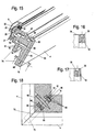
- FIG. 9 and 10 is a schematic representation of how the individual window frame leg 1 using the corner connection angle 50 with their respective miter cut surfaces 72 and 73 or 74 and 75 are put together, to get a corner connection that is flush with the edge.
- the two will be perpendicular to each other Angle legs 51 and 52 of a corner connection angle 50 each end in the shell profiles of the panels 5 positively inserted and the miter cut surfaces 72 to 75 are each preferred in a suitable device, with a suitable Adhesive, firmly and permanently attached to each other.
- Corner connection bracket 50 'used made of flat material exist and are profiled so that they are form-fitting fits in between the crossbar 57 and the top Profile section 59 lying cavity 63 of the double-shell Shell profile of the panel 8 with one each of her two legs, which run at right angles to each other 51 'and 52' can be introduced.
- a stable, permanently resilient connection receives, the miter cut surfaces 72 to 75 or 72 'to 75' of the wooden frame legs of both Casement frame as well as the window frame in each case to be provided with congruent grooves 80, each in closed channels for receiving a press-in, form self-curing connection medium 89 and which each start at an injection opening 87 and at one Vent opening 88 ends.
- a suitable connection medium 89 can be, for example a two-component adhesive or a resinous substance is used be in the liquid state easily into those of the congruent ones Grooves 80 channels formed evenly distributed, so that this completely with at the end of the pressing process the connecting medium 89 are filled. After curing of the connection medium 89 forms this over the entire Groove length a stable rigid positive connection between those with their miter cut surfaces 72 to 75 wooden frame legs butting each other in pairs 4 of a window sash or the wooden frame legs 7 of the frame.
- such a groove 80 which starts, for example, from the press-in opening 87 several longitudinal and transverse sections 81, 82, 83, 84, 85 and 86 exist, so as uniform as possible Distribution of the connection medium over the miter cut surface is achieved.
- These grooves 80 can for example with an end mill or end mill on a CNC machine according to the surface shape of the respective miter cut surfaces 72 to 75 to. 72 'to 75 'can be generated.
- the grooves each have an undercut profile, for example a T-profile 79 according to 16 or a symmetrical trapezoidal profile 78 according to FIG. 17, through which the hardened connecting medium 89 receives a better hold in the grooves 80.
- miter cut surfaces 72 to 75 of two abutting Wooden frame legs 4 and 7 each by at least one the miter cut surfaces 72, 73 across penetrating fastening screw 90 connected to each other (Fig. 18). It has proven to be advantageous that a fastening screw 90 is used, the has no screw head and the one with a pointed thread is provided, which is at least approximately stretches their entire length. One with wood screws preferred pointed thread creates a high in the wood tensile hold.
Landscapes
- Engineering & Computer Science (AREA)
- Civil Engineering (AREA)
- Structural Engineering (AREA)
- Wing Frames And Configurations (AREA)
- Joining Of Corner Units Of Frames Or Wings (AREA)
- Chemical And Physical Treatments For Wood And The Like (AREA)
- Laminated Bodies (AREA)
- Securing Of Glass Panes Or The Like (AREA)
- Door And Window Frames Mounted To Openings (AREA)
Claims (23)
- Profilé d'encadrement pour le cadre dormant et le cadre battant de fenêtres ou de portes en bois et métal, qui est composé d'une traverse (4, 7) de cadre en bois servant d'élément porteur et, à l'extérieur, d'un habillage de protection (5, 8) à une ou plusieurs coques en aluminium étiré à paroi mince, qui est assemblé avec la traverse du cadre en bois par des éléments d'assemblage s'encastrant les uns dans les autres avec un engagement positif, caractérisé en ce que l'habillage de protection (5, 8) présente un profilé à coques comprenant au moins deux ailes d'encastrement (20, 21) orientées longitudinalement qui s'étendent, à partir d'un segment de profilé (22, 35, 35', 65) s'étendant en biais ou transversalement à un plan de vitrage (17), à une certaine distance (a1 + a2) l'une de l'autre dans un plan de profilé (23, 24, 23', 24') essentiellement parallèle au plan (17) du vitrage et s'encastrent avec un engagement positif au moins approximativement ajusté dans une rainure de guidage (25, 26, 25', 26') de la traverse (4, 7) du cadre en bois, sachant qu'une surface d'appui (27, 27') de la traverse (4, 7) du cadre en bois s'étendant le long d'une rainure de guidage (25, 25') et une aile d'appui (28, 28') du profilé à coques venant coiffer ladite surface d'appui (27, 27') forment une cavité (29, 29') semblable à une rainure qui est destinée à recevoir au moins une garniture de compression élastique (30).
- Profilé d'encadrement selon la revendication 1, caractérisé en ce que les ailes d'encastrement (20, 21) sont décalées l'une par rapport à l'autre transversalement au plan (17) du vitrage.
- Profilé d'encadrement selon la revendication 1 ou 2, caractérisé en ce que la garniture de compression (30) est composée d'un corps en forme de barre, de tube ou de ruban en un matériau élastique.
- Profilé d'encadrement selon la revendication 3 ou 4, caractérisé en ce que la garniture de compression (30) est en caoutchouc ou un matériau analogue présentant une dureté d'au moins 45 shore A.
- Profilé d'encadrement selon la revendication 1, caractérisé en ce que la surface d'appui (27) et l'aile d'appui (28) se trouvent sur la face de la traverse (4) du cadre en bois qui est tournée vers le vitrage (14).
- Profilé d'encadrement selon la revendication 1 ou 5, caractérisé en ce que la surface d'appui pour la garniture de compression se trouve au voisinage immédiat de la rainure de guidage (25) recevant l'aile d'encastrement.
- Profilé d'encadrement selon la revendication 1 ou 6, caractérisé en ce que la cavité (29) semblable à une rainure qui est formée par la surface d'appui (27) et l'aile d'appui (28) présente une section transversale se rétrécissant vers le côté ouvert.
- Profilé d'encadrement selon la revendication 1 ou 7, caractérisé en ce que, dans le cas de traverses de cadre (1) d'un vantail de fenêtre, la cavité (29) destinée à recevoir la garniture de compression (30) est toujours située dans la zone du bord du vitrage (14).
- Profilé d'encadrement selon la revendication 1, caractérisé en ce que la rainure de guidage (25) de la traverse (4) du cadre en bois, qui est située côté vitrage, a une profondeur supérieure (T1) à la profondeur que nécessite l'aile d'encastrement (20) qui y est guidée.
- Profilé d'encadrement selon la revendication 9, caractérisé en ce que la rainure de guidage (25) de la traverse (4) du cadre en bois, qui est située côté vitrage, a une profondeur (T1) telle qu'entre le fond (25") de la rainure et l'aile de guidage (20), il reste un écart (a2) qui est inférieur à la profondeur de pénétration (T2) de la ou d'une seconde aile d'encastrement (21) dans sa rainure de guidage (26).
- Profilé d'encadrement selon la revendication 9 ou 10, caractérisé en ce que les ailes d'encastrement (20, 21) présentent chacune un bourrelet périphérique (32, 33) grâce auquel leur épaisseur (d) correspondant à la largeur (w) de leurs rainures de guidage (25, 26) correspond approximativement au double de l'épaisseur de paroi (d1) des autres parties du profilé.
- Profilé d'encadrement selon l'une des revendications 1 à 11, caractérisé en ce que le profilé à coques de l'habillage de protection (5) présente une aile d'extrémité (40) faisant face à l'aile d'appui (28) et formant avec cette dernière une rainure de profilé (41) destinée à recevoir par engagement positif une garniture de profilé (42) semblable à une bande.
- Profilé d'encadrement selon la revendication 1 ou l'une des revendications 2 à 12, caractérisé en ce qu'à l'intérieur d'un segment de coque extérieure (45) du profilé à coques, sur le côté de l'aile d'encastrement (20) qui est opposé à l'aile d'appui (28), ainsi que dans la zone inférieure dudit segment de coque extérieure (45) sont disposés de minces bordures (46,47) qui servent à maintenir des cornières d'assemblage d'angle (50) profilées de manière correspondante.
- Profilé d'encadrement selon l'une des revendications 1 à 13, caractérisé en ce qu'un habillage de protection (8) fixé au cadre dormant (2) est réalisé à double coque et est muni de deux garnitures de profilé (62) contre lesquelles sont appliqués, d'une part, une surface de butée (18) du cadre en bois (4) du battant et, d'autre part, un segment de paroi (36) de l'habillage de protection (5) fixé au cadre en bois (4) du battant.
- Profilé d'encadrement selon la revendication 14, caractérisé en ce que l'aile d'encastrement située côté vitrage est reliée par le biais d'une aile transversale à la paroi intérieure du profilé à coque double de l'habillage (8).
- Profilé d'encadrement selon la revendication 15, caractérisé en ce que l'aile transversale est reliée à la paroi intérieure par l'intermédiaire de deux segments de paroi s'étendant à l'oblique et de façon divergente.
- Profilé d'encadrement selon l'une des revendications 1 à 16, caractérisé en ce qu'une aile de liaison (35) qui relie l'aile d'encastrement (21) située sur la face extérieure d'une traverse (4, 7) du cadre en bois qui est opposée au vitrage (14) à un segment de paroi à coque (36), est dotée d'au moins un rétrécissement (37, 38) de la section transversale réalisé à la manière de nervures et s'étendant longitudinalement.
- Profilé d'encadrement selon l'une des revendications 1 à 17, caractérisé en ce que les surfaces en onglet (72 à 75) sont munies de rainures (80) coïncidant entre elles, qui forment des canaux fermés sur eux-mêmes afin de les remplir d'un produit de liaison (89) autodurcissant pouvant y être injecté, qui commencent au niveau d'un orifice d'injection (87) et se terminent au niveau d'un orifice de ventilation (88).
- Profilé d'encadrement selon la revendication 18, caractérisé en ce que l'orifice d'injection (87) et l'orifice de ventilation (88) sont disposés de façon symétrique par rapport aux surfaces en onglet (72/73) se touchant deux à deux, dans l'angle interne (91) de l'assemblage d'angle.
- Profilé d'encadrement selon la revendication 18 ou 19, caractérisé en ce que les rainures (80) sont munies d'orifices de ventilation supplémentaires (88') aux endroits où des poches d'air sont susceptibles de se former.
- Profilé d'encadrement selon l'une des revendications 18 à 20, caractérisé en ce que les rainures (80) présentent un profil en contre-dépouille, notamment un profil en T (79) ou un profil trapézoïdal (78).
- Profilé d'encadrement selon l'une des revendications 18 à 21, caractérisé en ce que les surfaces en onglet (72 à 75) de deux traverses (4) du cadre en bois aboutées sont reliées entre elles par au moins une vis de fixation (90) traversant les surfaces en onglet transversalement.
- Profilé d'encadrement selon la revendication 22, caractérisé en ce que la vis de fixation (90) ne comporte pas de tête et est munie d'un filet triangulaire qui s'étend au moins approximativement sur l'ensemble de sa longueur.
Priority Applications (1)
| Application Number | Priority Date | Filing Date | Title |
|---|---|---|---|
| EP02026610A EP1286015B1 (fr) | 1999-02-05 | 2000-02-04 | Assemblage d'angle de profilés de fenêtres ou de portes en bois-métal |
Applications Claiming Priority (2)
| Application Number | Priority Date | Filing Date | Title |
|---|---|---|---|
| DE29901972U DE29901972U1 (de) | 1999-02-05 | 1999-02-05 | Rahmenprofil für Holz-Metall-Fenster oder -Türen |
| DE29901972U | 1999-02-05 |
Related Child Applications (1)
| Application Number | Title | Priority Date | Filing Date |
|---|---|---|---|
| EP02026610A Division EP1286015B1 (fr) | 1999-02-05 | 2000-02-04 | Assemblage d'angle de profilés de fenêtres ou de portes en bois-métal |
Publications (3)
| Publication Number | Publication Date |
|---|---|
| EP1026357A2 EP1026357A2 (fr) | 2000-08-09 |
| EP1026357A3 EP1026357A3 (fr) | 2001-09-12 |
| EP1026357B1 true EP1026357B1 (fr) | 2004-08-11 |
Family
ID=8068959
Family Applications (2)
| Application Number | Title | Priority Date | Filing Date |
|---|---|---|---|
| EP00102366A Expired - Lifetime EP1026357B1 (fr) | 1999-02-05 | 2000-02-04 | Profilé d'encadrement pour fenêtres ou portes en bois-métal |
| EP02026610A Expired - Lifetime EP1286015B1 (fr) | 1999-02-05 | 2000-02-04 | Assemblage d'angle de profilés de fenêtres ou de portes en bois-métal |
Family Applications After (1)
| Application Number | Title | Priority Date | Filing Date |
|---|---|---|---|
| EP02026610A Expired - Lifetime EP1286015B1 (fr) | 1999-02-05 | 2000-02-04 | Assemblage d'angle de profilés de fenêtres ou de portes en bois-métal |
Country Status (3)
| Country | Link |
|---|---|
| EP (2) | EP1026357B1 (fr) |
| AT (2) | ATE270378T1 (fr) |
| DE (3) | DE29901972U1 (fr) |
Families Citing this family (16)
| Publication number | Priority date | Publication date | Assignee | Title |
|---|---|---|---|---|
| DE20004154U1 (de) * | 2000-03-08 | 2001-07-19 | Heuser, Ralf, 56357 Miehlen | Hochwärmedämmendes Fenster oder Tür |
| DE10055780A1 (de) * | 2000-11-10 | 2002-05-29 | Raico Bautechnik Gmbh | Abdeckprofilsystem für Fenster-oder Türprofile |
| FR2820456B1 (fr) * | 2001-02-06 | 2003-12-19 | Albert Rivier | Dispositif de ventilation mixte pour menuiseries exterieures, notamment une fenetre ou une porte-fenetre |
| DE10114233B4 (de) * | 2001-03-22 | 2006-07-27 | Hermann Gutmann Werke Ag | Holz-Alu-Fenster |
| FR2884277B1 (fr) * | 2005-04-08 | 2011-03-04 | Profiles Extrudes Pour Fenetres Et Portes | Profile de battement exterieur pour ouvrant de fenetre |
| DE102007033984A1 (de) * | 2007-07-19 | 2009-01-29 | Hermann Gutmann Werke Ag | Blendrahmenkonstruktion sowie Blendrahmenanordnung |
| ITVR20080120A1 (it) * | 2008-10-30 | 2010-04-30 | Alfredo Pegoraro | Procedimento per la realizzazione di telai per serramenti e simili |
| GB2487910B (en) * | 2011-02-04 | 2017-05-10 | Bowater Building Products Ltd | window or door frame |
| DE102013006292A1 (de) * | 2013-04-12 | 2014-10-16 | Rhenocoll-Werk E.K. | Verkleidung für den Rahmen eines Fensters, Profilleiste für eine solche Verkleidung, Rahmenkonstruktion mit einer solchen Verkleidung und Verfahren zur Herstellung einer solchen Verkleidung |
| CN103603574A (zh) * | 2013-11-06 | 2014-02-26 | 姚刚 | 一种单边压锁铝木型材结构 |
| NL2017775B1 (en) * | 2016-11-11 | 2018-05-24 | Buva Rationele Bouwprodukten B V | Bottom profile and plug for a window frame |
| CN107269158A (zh) * | 2017-08-08 | 2017-10-20 | 烟台海林建材有限公司 | 一种下框铝型材及具有排水系统的门窗 |
| DE102017121096A1 (de) * | 2017-09-12 | 2019-03-14 | G.S. Georg Stemeseder Gmbh | Kunststoff-Metall-Fenstersystem |
| EP3581750A1 (fr) * | 2018-06-14 | 2019-12-18 | Profine GmbH | Cadre pourvu de panneau de parement et système de profilés destiné à sa fabrication |
| FR3123939B1 (fr) * | 2021-06-11 | 2023-10-06 | Etablissement Lorillard | Structure de Fenêtre ou de porte et barrette thermique pour ladite structure |
| FR3123938B1 (fr) * | 2021-06-11 | 2023-06-30 | Etablissement Lorillard | Structure de Fenêtre ou de porte et barrette thermique pour ladite structure |
Family Cites Families (9)
| Publication number | Priority date | Publication date | Assignee | Title |
|---|---|---|---|---|
| DE1704026A1 (de) * | 1967-12-22 | 1971-05-06 | Michael Emmerich | Verfahren und Vorrichtung zum Verbinden von Staeben und Profilen an deren einander zugewandten Enden |
| DE2458315A1 (de) | 1974-12-10 | 1976-06-16 | Rolscreen Co | Fensterfluegel o.dgl. |
| DE2724377A1 (de) | 1977-05-28 | 1978-11-30 | Caprano & Brunnhofer | Profilstabaggregat |
| WO1981000588A1 (fr) * | 1979-08-29 | 1981-03-05 | M Hewitt | Profiles en plastique armes et fabrication de cadres de fenetres et autres a partir de ces profils |
| GB2105430A (en) * | 1981-08-03 | 1983-03-23 | Blacknell Buildings Ltd | Corner joint |
| DE4403087C2 (de) * | 1994-02-02 | 1996-08-08 | Gutmann Hermann Werke Gmbh | Holz-Alu-Fenster |
| DE4410075A1 (de) | 1994-03-23 | 1995-10-05 | Thyssen Polymer Gmbh | Fenster |
| AT400167B (de) | 1994-04-18 | 1995-10-25 | Silber Franz | Verfahren zum herstellen eines rahmens für fenster oder türen |
| FR2759111B1 (fr) * | 1997-02-06 | 1999-10-22 | Alcan France | Dispositif pour l'assemblage de profiles d'un chassis de porte, fenetre ou analogue |
-
1999
- 1999-02-05 DE DE29901972U patent/DE29901972U1/de not_active Expired - Lifetime
-
2000
- 2000-02-04 EP EP00102366A patent/EP1026357B1/fr not_active Expired - Lifetime
- 2000-02-04 DE DE50006986T patent/DE50006986D1/de not_active Expired - Lifetime
- 2000-02-04 DE DE50007331T patent/DE50007331D1/de not_active Expired - Fee Related
- 2000-02-04 EP EP02026610A patent/EP1286015B1/fr not_active Expired - Lifetime
- 2000-02-04 AT AT02026610T patent/ATE270378T1/de not_active IP Right Cessation
- 2000-02-04 AT AT00102366T patent/ATE273433T1/de not_active IP Right Cessation
Also Published As
| Publication number | Publication date |
|---|---|
| DE50007331D1 (de) | 2004-09-16 |
| EP1026357A3 (fr) | 2001-09-12 |
| EP1026357A2 (fr) | 2000-08-09 |
| EP1286015B1 (fr) | 2004-06-30 |
| DE50006986D1 (de) | 2004-08-05 |
| DE29901972U1 (de) | 1999-05-06 |
| EP1286015A1 (fr) | 2003-02-26 |
| ATE273433T1 (de) | 2004-08-15 |
| ATE270378T1 (de) | 2004-07-15 |
Similar Documents
| Publication | Publication Date | Title |
|---|---|---|
| EP1026357B1 (fr) | Profilé d'encadrement pour fenêtres ou portes en bois-métal | |
| EP0100991A2 (fr) | Profil composé | |
| DD154812A5 (de) | Mehrscheiben-isolierglas und verfahren zu seiner herstellung | |
| DE2401307A1 (de) | Fensterkonstruktion | |
| DE2608325C3 (de) | Mehrteiliger, wärmegedämmter Metallprofilstab zum Befestigen von Wand- und Fensterelementen | |
| EP0724061B1 (fr) | Elément de raccord | |
| DE2407196A1 (de) | Treibstangenbeschlag fuer fenster, tueren o.dgl., insbesondere kunststoff-fluegelrahmen | |
| DE3532593A1 (de) | Extrudierter kunststoffhohlprofilstab fuer rahmen von fenstern und tueren | |
| DE19828382C2 (de) | Anordnung zum Befestigen eines einen Hohlquerschnitt aufweisenden Pfostens am Blendrahmen eines Fensters oder einer Türe aus Kunststoff oder Leichtmetall | |
| DE4338181C1 (de) | Kunststoff-Hohlprofil | |
| DE29620153U1 (de) | Verbindung für winklig aneinanderstoßende Hohlprofilstäbe | |
| AT390473B (de) | Profilrahmen fuer schiebetueren oder -fenster | |
| DE2814953A1 (de) | Einrichtung zum befestigen eines profilrahmens an einem grundrahmen | |
| DE29704349U1 (de) | Hohlprofil, insbesondere aus Kunststoff, zur Bildung eines Abdeckrahmens zur Verkleidung von Holzrahmen | |
| DE1683625A1 (de) | Verfahren zur Herstellung von Fenstern,nach diesem Verfahren hergestellte Fenster sowie Vorrichtung und Profil zur Herstellung dieses Fensters | |
| EP4202170B1 (fr) | Connecteur, joint bout à bout et procédé de fabrication associé | |
| DE1509172A1 (de) | Fenster bzw. Tuer,dessen bzw. deren feststehender Zargenrahmen und beweglicher Fluegelrahmen je aus einem Holzrahmen und einem damit verbundenen Metall- oder Kunststoffrahmen bestehen | |
| DE9206375U1 (de) | Tragwerk für Glasfassaden, -wände und/oder -dächer | |
| EP0304830A2 (fr) | Cadre composé de profilés porteurs en bois, matière plastique ou matière composite | |
| AT249337B (de) | Fenster bzw. Tür | |
| EP1529892A2 (fr) | Elément d'étanchéité pour une construction à traverses et montants | |
| EP4325017A1 (fr) | Profilé isolant pour relier deux éléments profilés pour la réalisation d'un profilé isolé thermiquement et un tel profilé | |
| DE29713820U1 (de) | Fenster mit Blendrahmen und Flügelrahmen mit Zwangsbelüftung | |
| DE2222484A1 (de) | Wohnwagenfenster | |
| AT12155U1 (de) | Führungsschiene |
Legal Events
| Date | Code | Title | Description |
|---|---|---|---|
| PUAI | Public reference made under article 153(3) epc to a published international application that has entered the european phase |
Free format text: ORIGINAL CODE: 0009012 |
|
| AK | Designated contracting states |
Kind code of ref document: A2 Designated state(s): AT BE CH CY DE DK ES FI FR GB GR IE IT LI LU MC NL PT SE |
|
| AX | Request for extension of the european patent |
Free format text: AL;LT;LV;MK;RO;SI |
|
| PUAL | Search report despatched |
Free format text: ORIGINAL CODE: 0009013 |
|
| AK | Designated contracting states |
Kind code of ref document: A3 Designated state(s): AT BE CH CY DE DK ES FI FR GB GR IE IT LI LU MC NL PT SE |
|
| AX | Request for extension of the european patent |
Free format text: AL;LT;LV;MK;RO;SI |
|
| 17P | Request for examination filed |
Effective date: 20011025 |
|
| AKX | Designation fees paid |
Free format text: AT BE CH CY DE DK ES FI FR GB GR IE IT LI LU MC NL PT SE |
|
| RAP1 | Party data changed (applicant data changed or rights of an application transferred) |
Owner name: FENOVA GMBH PROFILSYSTEME |
|
| 17Q | First examination report despatched |
Effective date: 20030414 |
|
| GRAP | Despatch of communication of intention to grant a patent |
Free format text: ORIGINAL CODE: EPIDOSNIGR1 |
|
| GRAS | Grant fee paid |
Free format text: ORIGINAL CODE: EPIDOSNIGR3 |
|
| GRAA | (expected) grant |
Free format text: ORIGINAL CODE: 0009210 |
|
| AK | Designated contracting states |
Kind code of ref document: B1 Designated state(s): AT BE CH CY DE DK ES FI FR GB GR IE IT LI LU MC NL PT SE |
|
| PG25 | Lapsed in a contracting state [announced via postgrant information from national office to epo] |
Ref country code: NL Free format text: LAPSE BECAUSE OF FAILURE TO SUBMIT A TRANSLATION OF THE DESCRIPTION OR TO PAY THE FEE WITHIN THE PRESCRIBED TIME-LIMIT Effective date: 20040811 Ref country code: IT Free format text: LAPSE BECAUSE OF FAILURE TO SUBMIT A TRANSLATION OF THE DESCRIPTION OR TO PAY THE FEE WITHIN THE PRESCRIBED TIME-LIMIT;WARNING: LAPSES OF ITALIAN PATENTS WITH EFFECTIVE DATE BEFORE 2007 MAY HAVE OCCURRED AT ANY TIME BEFORE 2007. THE CORRECT EFFECTIVE DATE MAY BE DIFFERENT FROM THE ONE RECORDED. Effective date: 20040811 Ref country code: IE Free format text: LAPSE BECAUSE OF FAILURE TO SUBMIT A TRANSLATION OF THE DESCRIPTION OR TO PAY THE FEE WITHIN THE PRESCRIBED TIME-LIMIT Effective date: 20040811 Ref country code: GB Free format text: LAPSE BECAUSE OF FAILURE TO SUBMIT A TRANSLATION OF THE DESCRIPTION OR TO PAY THE FEE WITHIN THE PRESCRIBED TIME-LIMIT Effective date: 20040811 Ref country code: FR Free format text: LAPSE BECAUSE OF FAILURE TO SUBMIT A TRANSLATION OF THE DESCRIPTION OR TO PAY THE FEE WITHIN THE PRESCRIBED TIME-LIMIT Effective date: 20040811 Ref country code: FI Free format text: LAPSE BECAUSE OF FAILURE TO SUBMIT A TRANSLATION OF THE DESCRIPTION OR TO PAY THE FEE WITHIN THE PRESCRIBED TIME-LIMIT Effective date: 20040811 |
|
| REG | Reference to a national code |
Ref country code: GB Ref legal event code: FG4D Free format text: NOT ENGLISH |
|
| REG | Reference to a national code |
Ref country code: CH Ref legal event code: EP |
|
| REG | Reference to a national code |
Ref country code: IE Ref legal event code: FG4D Free format text: GERMAN |
|
| REF | Corresponds to: |
Ref document number: 50007331 Country of ref document: DE Date of ref document: 20040916 Kind code of ref document: P |
|
| PG25 | Lapsed in a contracting state [announced via postgrant information from national office to epo] |
Ref country code: SE Free format text: LAPSE BECAUSE OF FAILURE TO SUBMIT A TRANSLATION OF THE DESCRIPTION OR TO PAY THE FEE WITHIN THE PRESCRIBED TIME-LIMIT Effective date: 20041111 Ref country code: GR Free format text: LAPSE BECAUSE OF FAILURE TO SUBMIT A TRANSLATION OF THE DESCRIPTION OR TO PAY THE FEE WITHIN THE PRESCRIBED TIME-LIMIT Effective date: 20041111 Ref country code: DK Free format text: LAPSE BECAUSE OF FAILURE TO SUBMIT A TRANSLATION OF THE DESCRIPTION OR TO PAY THE FEE WITHIN THE PRESCRIBED TIME-LIMIT Effective date: 20041111 |
|
| PG25 | Lapsed in a contracting state [announced via postgrant information from national office to epo] |
Ref country code: ES Free format text: LAPSE BECAUSE OF FAILURE TO SUBMIT A TRANSLATION OF THE DESCRIPTION OR TO PAY THE FEE WITHIN THE PRESCRIBED TIME-LIMIT Effective date: 20041122 |
|
| NLV1 | Nl: lapsed or annulled due to failure to fulfill the requirements of art. 29p and 29m of the patents act | ||
| PG25 | Lapsed in a contracting state [announced via postgrant information from national office to epo] |
Ref country code: LU Free format text: LAPSE BECAUSE OF NON-PAYMENT OF DUE FEES Effective date: 20050204 Ref country code: CY Free format text: LAPSE BECAUSE OF FAILURE TO SUBMIT A TRANSLATION OF THE DESCRIPTION OR TO PAY THE FEE WITHIN THE PRESCRIBED TIME-LIMIT Effective date: 20050204 Ref country code: AT Free format text: LAPSE BECAUSE OF NON-PAYMENT OF DUE FEES Effective date: 20050204 |
|
| PG25 | Lapsed in a contracting state [announced via postgrant information from national office to epo] |
Ref country code: MC Free format text: LAPSE BECAUSE OF NON-PAYMENT OF DUE FEES Effective date: 20050228 Ref country code: LI Free format text: LAPSE BECAUSE OF NON-PAYMENT OF DUE FEES Effective date: 20050228 Ref country code: CH Free format text: LAPSE BECAUSE OF NON-PAYMENT OF DUE FEES Effective date: 20050228 Ref country code: BE Free format text: LAPSE BECAUSE OF NON-PAYMENT OF DUE FEES Effective date: 20050228 |
|
| GBV | Gb: ep patent (uk) treated as always having been void in accordance with gb section 77(7)/1977 [no translation filed] |
Effective date: 20040811 |
|
| REG | Reference to a national code |
Ref country code: IE Ref legal event code: FD4D |
|
| PLBE | No opposition filed within time limit |
Free format text: ORIGINAL CODE: 0009261 |
|
| STAA | Information on the status of an ep patent application or granted ep patent |
Free format text: STATUS: NO OPPOSITION FILED WITHIN TIME LIMIT |
|
| 26N | No opposition filed |
Effective date: 20050512 |
|
| EN | Fr: translation not filed | ||
| EN | Fr: translation not filed | ||
| BERE | Be: lapsed |
Owner name: *FENOVA G.M.B.H. PROFILSYSTEME Effective date: 20050228 |
|
| REG | Reference to a national code |
Ref country code: CH Ref legal event code: PL |
|
| PGFP | Annual fee paid to national office [announced via postgrant information from national office to epo] |
Ref country code: DE Payment date: 20070117 Year of fee payment: 8 |
|
| BERE | Be: lapsed |
Owner name: *FENOVA G.M.B.H. PROFILSYSTEME Effective date: 20050228 |
|
| PG25 | Lapsed in a contracting state [announced via postgrant information from national office to epo] |
Ref country code: PT Free format text: LAPSE BECAUSE OF NON-PAYMENT OF DUE FEES Effective date: 20050111 |
|
| PG25 | Lapsed in a contracting state [announced via postgrant information from national office to epo] |
Ref country code: DE Free format text: LAPSE BECAUSE OF NON-PAYMENT OF DUE FEES Effective date: 20080902 |