EP1026408A2 - Dispositif d'actionnement pour un appareil de transmission et/ou de réception - Google Patents
Dispositif d'actionnement pour un appareil de transmission et/ou de réception Download PDFInfo
- Publication number
- EP1026408A2 EP1026408A2 EP00100537A EP00100537A EP1026408A2 EP 1026408 A2 EP1026408 A2 EP 1026408A2 EP 00100537 A EP00100537 A EP 00100537A EP 00100537 A EP00100537 A EP 00100537A EP 1026408 A2 EP1026408 A2 EP 1026408A2
- Authority
- EP
- European Patent Office
- Prior art keywords
- piston
- drive shaft
- piston rod
- drive device
- rotary drive
- Prior art date
- Legal status (The legal status is an assumption and is not a legal conclusion. Google has not performed a legal analysis and makes no representation as to the accuracy of the status listed.)
- Withdrawn
Links
- 230000033001 locomotion Effects 0.000 claims description 16
- 230000005540 biological transmission Effects 0.000 claims description 11
- 230000008878 coupling Effects 0.000 claims description 6
- 238000010168 coupling process Methods 0.000 claims description 6
- 238000005859 coupling reaction Methods 0.000 claims description 6
- 230000001681 protective effect Effects 0.000 claims description 5
- ZZUFCTLCJUWOSV-UHFFFAOYSA-N furosemide Chemical compound C1=C(Cl)C(S(=O)(=O)N)=CC(C(O)=O)=C1NCC1=CC=CO1 ZZUFCTLCJUWOSV-UHFFFAOYSA-N 0.000 claims description 2
- 239000000314 lubricant Substances 0.000 claims description 2
- 239000004020 conductor Substances 0.000 abstract 1
- 230000009977 dual effect Effects 0.000 abstract 1
- 238000007789 sealing Methods 0.000 description 16
- 238000006073 displacement reaction Methods 0.000 description 2
- 239000007788 liquid Substances 0.000 description 2
- 238000001514 detection method Methods 0.000 description 1
- 230000007613 environmental effect Effects 0.000 description 1
- 210000003746 feather Anatomy 0.000 description 1
- 239000012530 fluid Substances 0.000 description 1
- 239000010720 hydraulic oil Substances 0.000 description 1
- 230000002452 interceptive effect Effects 0.000 description 1
- 239000010687 lubricating oil Substances 0.000 description 1
- 230000036316 preload Effects 0.000 description 1
Images


Classifications
-
- F—MECHANICAL ENGINEERING; LIGHTING; HEATING; WEAPONS; BLASTING
- F15—FLUID-PRESSURE ACTUATORS; HYDRAULICS OR PNEUMATICS IN GENERAL
- F15B—SYSTEMS ACTING BY MEANS OF FLUIDS IN GENERAL; FLUID-PRESSURE ACTUATORS, e.g. SERVOMOTORS; DETAILS OF FLUID-PRESSURE SYSTEMS, NOT OTHERWISE PROVIDED FOR
- F15B15/00—Fluid-actuated devices for displacing a member from one position to another; Gearing associated therewith
- F15B15/08—Characterised by the construction of the motor unit
- F15B15/14—Characterised by the construction of the motor unit of the straight-cylinder type
- F15B15/149—Fluid interconnections, e.g. fluid connectors, passages
-
- F—MECHANICAL ENGINEERING; LIGHTING; HEATING; WEAPONS; BLASTING
- F15—FLUID-PRESSURE ACTUATORS; HYDRAULICS OR PNEUMATICS IN GENERAL
- F15B—SYSTEMS ACTING BY MEANS OF FLUIDS IN GENERAL; FLUID-PRESSURE ACTUATORS, e.g. SERVOMOTORS; DETAILS OF FLUID-PRESSURE SYSTEMS, NOT OTHERWISE PROVIDED FOR
- F15B15/00—Fluid-actuated devices for displacing a member from one position to another; Gearing associated therewith
- F15B15/02—Mechanical layout characterised by the means for converting the movement of the fluid-actuated element into movement of the finally-operated member
- F15B15/06—Mechanical layout characterised by the means for converting the movement of the fluid-actuated element into movement of the finally-operated member for mechanically converting rectilinear movement into non- rectilinear movement
- F15B15/063—Actuator having both linear and rotary output, i.e. dual action actuator
-
- F—MECHANICAL ENGINEERING; LIGHTING; HEATING; WEAPONS; BLASTING
- F15—FLUID-PRESSURE ACTUATORS; HYDRAULICS OR PNEUMATICS IN GENERAL
- F15B—SYSTEMS ACTING BY MEANS OF FLUIDS IN GENERAL; FLUID-PRESSURE ACTUATORS, e.g. SERVOMOTORS; DETAILS OF FLUID-PRESSURE SYSTEMS, NOT OTHERWISE PROVIDED FOR
- F15B15/00—Fluid-actuated devices for displacing a member from one position to another; Gearing associated therewith
- F15B15/08—Characterised by the construction of the motor unit
- F15B15/14—Characterised by the construction of the motor unit of the straight-cylinder type
- F15B15/1423—Component parts; Constructional details
- F15B15/1457—Piston rods
Definitions
- the invention relates to a drive device for a transmission and / or Receiving device, in particular for a sonar transmission and Receiving device on a ship, with a double-acting, preferably hydraulically actuated cylinder, the one piston and one linearly extendable and retractable from a cylinder housing and by one Drive shaft rotatable piston rod, the piston and the piston rod are hobl and also a hollow rotary drive shaft record against which they can be moved linearly.
- Drive devices of this type are known, for example, from EP 0 735 276 A1 known.
- the rotational movement of a rotary drive shaft is one endlessly rotating rotor via a coupling element on the piston and then transfer to the piston rod using feather keys.
- One in The center bore provided on the drive shaft is used for pressure-free Return of the fluid, which is in a cavity of the piston rod arrives when the piston rod is extended.
- the present invention is therefore based on the problem of a To provide drive device in which the above Disadvantages are overcome.
- the drive device should be a secure supply of, for example, electrical connecting lines ensure a sonar transmitter and receiver.
- the problem is solved in that the hollow Interior of the rotary drive shaft relative to the working medium of the Cylinder is sealed and that in the hollow interior, for example electrical, pneumatic or hydraulic connecting lines for the transmitting and / or receiving device can be carried out.
- the sealing takes place preferably by means of a first sealing arrangement between the Piston rod and the rotary drive shaft and a second Sealing arrangement between the one cylinder sleeve and one Cylinder housing with cylinder flange and the rotary drive shaft.
- the working medium is preferably a liquid, for example a Hydraulic oil, however, can in principle also be compressed air.
- the piston and the piston rod is made in one piece. This will not only the sealing of the interior of the rotary drive shaft against the Working medium facilitates, but also the coupling of the linear movement of the piston with the piston rod improved.
- the drive device coupling means for transmitting the rotary movement the rotary drive shaft on the piston preferably according to claim 4 a guide disc fixed to the piston with the one Cross section of the opening corresponding to the rotary drive shaft.
- the rotary drive shaft has in particular two to each other and to Parallel key faces. Through the form fit it happens between the rotary drive shaft and the guide disc a coupling of the rotary movement from the rotary drive shaft to the Piston or the piston rod.
- the rotary drive shaft can also for example, triangular, quadrangular, hexagonal or octagonal.
- the piston or the guide disc slides linearly along the Rotary drive shaft. Pistons and piston rods are therefore in everyone Linear position of the rotary drive shaft in both directions of rotation drivable.
- the key faces in a cross section perpendicular to the drive axis Circular segment-shaped recesses for receiving a Lubricant, for example a lubricating oil.
- the guide disc also has axial holes for volume compensation, for example during a linear movement of the piston.
- the rotary drive shaft by means of a preferably self-locking Worm gear driven by a motor, preferably one hydraulic motor attached to the cylinder housing.
- a motor preferably one hydraulic motor attached to the cylinder housing.
- By self-locking the worm gear prevents the position of the Rotary drive shaft due to the on the piston rod specified device acting forces undesirably changed.
- Hydro engine that converts hydraulic energy into mechanical energy comes a variety of different design principles and Types considered, taking into account the required Parameters speed, torque and drive power a is to be selected.
- other motor principles can be considered for example the use of an electric motor, which may be under Taking into account the environmental conditions must be encapsulated.
- a flange close to the end of the piston rod Piston rod can be fixed on which the transmitting and / or receiving device is attachable.
- the flange can be made using, for example Sealing thread or using sealing rings on the Piston rod can be screwed on.
- the flange preferably has a central opening for carrying out the hollow interior of the Rotary drive shaft connecting lines for transmission and Receiving device on. This is also using a Sealing arrangement on the side of the piston rod opposite Attachable flange.
- the device has a first sensor for the angular position or the rotation of the piston rod and a second sensor for the linear position or the linear movement.
- the first and second sensor is preferably an electrical one Potentiometer.
- Worm gear has a first end with the first sensor interacting first rope set.
- the worm wheel is on the rotary drive shaft preferably by means of at least one clamping ring clamped to which the first end of the first rope is attached.
- the first Sensor can be arranged in the immediate vicinity of the clamping ring and pick up the second end of the first rope.
- the special embodiment according to claim 10 is on from Cylinder housing distal end of the piston rod a first end of an in a telescopically extendable and collapsible Protective tube guided and interacting with the second sensor second rope set. That in the hollow interior of the rotary drive shaft Protective tube prevents the second rope from jamming the connecting lines also running there for the transmission and / or Receiving device.
- the second end of the second rope is out the end of the rotary drive shaft in the axial direction and then connected to the second sensor via a deflection roller.
- the piston at least in the retracted position by means of a on the cylinder housing lockable locking device detachably lockable. This prevents that the piston and thus the transmitting and / or receiving device, for example, under the influence of weight, automatically drives in.
- the locking can also take place in several linear positions of the piston. In the same way, there is a finding of one or several rotational positions into consideration.
- the locking means engaging in a recess on the piston, preferably spring-loaded and hydraulically operated Locking bolt on.
- the spring force leads to a preload on the Locking bolt in the direction of the recess and thereby to one automatic detection when reaching the end position.
- an annular surface of the locking bolt via a separate one Pressurized control connection and counter the locking bolt the spring force moves out of the recess.
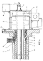
- FIG. 1a and 1b show a side view of the rotary / linear drive device according to the invention 1 in cross section with a double-acting, preferably hydraulically actuated cylinder, the piston 2 and one linearly extendable and retractable from a cylinder sleeve 3 and around one Drive shaft 4 includes rotatable piston rod 5.
- Pistons 2 and Piston rod 5 are made in one piece and hollow. In her hollow The interior of the piston 2 and the piston rod 5 also take one hollow rotary drive shaft 6, against which they are linearly parallel to Drive axis 4 are movable.
- the rotary drive shaft 6 projects above the Cylinder flange 7, which together with the cylinder sleeve 3 Forms cylinder housing, and carries a worm wheel 8, which by means of a Clamping ring 9 is attached to the rotary drive shaft 6 and that over a (Not shown) worm can be driven by a hydraulic motor 11.
- a first end of a first rope 12 is fixed to the tension ring 9, whose second end with a first sensor 10 in the form of a Angle encoder 10 cooperates, which is preferably an electrical Potentiometer.
- a first sensor 10 in the form of a Angle encoder 10 cooperates
- At the of the cylinder sleeve 3 and in particular from Cylinder flange 7 distal end of the piston rod 5 is tight with this connected a flange 13 attached to which a first end of a second Rope 14 is fastened in a telescopically pullable and collapsible protective tube 15 is guided and the second End with a second sensor 16 for the linear position or the linear movement of the flange 15 or the piston rod 5 cooperates.
- the second sensor 16 is also concerned preferably around an electrical potentiometer.
- On the flange 13 is the (not shown) transmitting and / or receiving device, preferably by means of a screw connection, can be fixed in such a way that a liquid and / or gast
- the axial movement of the piston 2 is by inserted in this and on the Guide ring 21 guided on the inner surface of the cylinder sleeve 3.
- the axial movement of the piston rod 5 is both in the rotary drive shaft 6 inserted and abutting the piston rod 5 Guide rings 22 as well as in one on the cylinder flange 7 screwed distant end of the housing sleeve 3
- Piston rod guide 19 inserted and abutting the piston rod 5 Guide rings 20 out.
- the seal between the piston rod 5 and the piston rod guide 19 is replaced by a first inserted therein Sealing arrangement 18b accomplished.
- the seal between the pistons 2 and the cylinder sleeve 3 is inserted into the piston 2 second sealing arrangement 17 accomplished.
- the seal between the Piston rod 5 and the rotary drive shaft 6 is replaced by a third, in the rotary drive shaft 6 introduced sealing arrangement 18a from Cylinder flange 7 far end of the rotary drive shaft 6 accomplished.
- the seal between the rotary drive shaft 6 and the Cylinder flange 7 is accomplished by a fourth sealing arrangement 23.
- the sealing arrangements 17, 18a, 18b, 23 can be several in the axial direction Sealing means arranged one behind the other, for example metallic piston rings or O-rings. You can also the piston guide rings 20, 21, 22 several in the axial direction elements arranged one behind the other.
- the rotary drive shaft 6 has two opposite key surfaces 25, on which one on Piston 2 fixed guide plate 26 is guided against rotation, with a central corresponding to the cross section of the rotary drive shaft 6 Opening is provided. This allows the piston 2 and the piston rod 5 in each linear position by means of the rotary drive shaft 6 from the hydraulic motor 11 can be rotated.
- FIG. 2 shows a section of the device according to the invention 1 in the area of the locking means 28.
- the locking means 28 has a two-part Housing and can be pressed or screwed into the cylinder sleeve 3.
- a central bore 32 in the locking bolt 30 leads to a Pressure equalization during the movement of the locking bolt 30.
- Medium a preferably hydraulic pressurization at the control connection 33 the locking pin 30 becomes counter to the force of the coil spring 29 moved back from the recess 31 and gives the piston 2 for one Axial movement free.
- First and second sealing arrangements 36, 37 and first and second guide means 34, 35 ensure a safe and tight Guiding the locking bolt 30 in the locking means 28.
- the pressure on the locking bolt 30 is in particular via an annular surface 38 provided thereon Extending the piston 2 first pressurized the port 33, to retract the locking bolt 30 and only then the Working space of the cylinder pressurized to the piston 2 to extend.
- the centric Opening 39 corresponds to the cross section of the rotary drive shaft 6 and has in particular two opposite and parallel to each other, Surfaces 40 corresponding to the key surfaces 25 of the rotary drive shaft 6 on.
- the key disk 26 for the Have volume compensation axial bores corresponds to the cross section of the rotary drive shaft 6 and has in particular two opposite and parallel to each other.
- FIG. 4 shows a view IV of the device 1 of FIG. 1a. That from the Rotary drive shaft 6 emerging second rope 14 is via a pulley 41 fed to the second sensor 16, which detects the linear movement of the piston 2 or the piston rod 5.
Landscapes
- Engineering & Computer Science (AREA)
- Physics & Mathematics (AREA)
- Fluid Mechanics (AREA)
- Mechanical Engineering (AREA)
- General Engineering & Computer Science (AREA)
- Chemical & Material Sciences (AREA)
- Analytical Chemistry (AREA)
- Actuator (AREA)
- Measurement Of Velocity Or Position Using Acoustic Or Ultrasonic Waves (AREA)
Applications Claiming Priority (2)
| Application Number | Priority Date | Filing Date | Title |
|---|---|---|---|
| DE19904942 | 1999-02-06 | ||
| DE19904942A DE19904942B4 (de) | 1999-02-06 | 1999-02-06 | Antriebsvorrichtung für eine Sende- und/oder Empfangseinrichtung, insbesondere für eine Sonar-Sende- und Empfangseinrichtung auf einem Schiff |
Publications (2)
| Publication Number | Publication Date |
|---|---|
| EP1026408A2 true EP1026408A2 (fr) | 2000-08-09 |
| EP1026408A3 EP1026408A3 (fr) | 2002-06-19 |
Family
ID=7896701
Family Applications (1)
| Application Number | Title | Priority Date | Filing Date |
|---|---|---|---|
| EP00100537A Withdrawn EP1026408A3 (fr) | 1999-02-06 | 2000-01-12 | Dispositif d'actionnement pour un appareil de transmission et/ou de réception |
Country Status (2)
| Country | Link |
|---|---|
| EP (1) | EP1026408A3 (fr) |
| DE (1) | DE19904942B4 (fr) |
Families Citing this family (1)
| Publication number | Priority date | Publication date | Assignee | Title |
|---|---|---|---|---|
| JP4217981B2 (ja) * | 2005-02-08 | 2009-02-04 | Smc株式会社 | 直動・回転複合アクチュエータ |
Citations (1)
| Publication number | Priority date | Publication date | Assignee | Title |
|---|---|---|---|---|
| EP0735276A1 (fr) | 1995-03-29 | 1996-10-02 | Hydraulik Techniek Emmen B.V. | Vérin à mouvement de translation et de rotation |
Family Cites Families (6)
| Publication number | Priority date | Publication date | Assignee | Title |
|---|---|---|---|---|
| US3302469A (en) * | 1964-10-30 | 1967-02-07 | Alessandro Calzoni Spa | Apparatus for controlling the translational and rotational movements of a rod |
| SE391494B (sv) * | 1974-05-17 | 1977-02-21 | Kockums Mekaniska Verkstads Ab | Anordning vid tryckmediumcylinder med forskjutbar kolv |
| DE8226748U1 (de) * | 1982-09-23 | 1983-12-08 | BIG LIFT Maschinenbau- u. Vertriebs GmbH, 6050 Offenbach | Teleskopantennenmast |
| DE3316026A1 (de) * | 1983-05-03 | 1984-11-08 | Bundesrepublik Deutschland, vertreten durch den Bundesminister der Verteidigung, dieser vertreten durch den Präsidenten des Bundesamtes für Wehrtechnik und Beschaffung, 5400 Koblenz | Aufnahmevorrichtung fuer schleppantennen auf u-booten |
| DE4219831A1 (de) * | 1992-06-17 | 1993-12-23 | Abs International Sa St Blaise | Radar-Rundumantenne für Luft- und/oder Wasserfahrzeuge |
| DE4229989A1 (de) * | 1992-09-08 | 1994-03-10 | Festo Kg | Dreh-Linear-Einheit |
-
1999
- 1999-02-06 DE DE19904942A patent/DE19904942B4/de not_active Expired - Fee Related
-
2000
- 2000-01-12 EP EP00100537A patent/EP1026408A3/fr not_active Withdrawn
Patent Citations (1)
| Publication number | Priority date | Publication date | Assignee | Title |
|---|---|---|---|---|
| EP0735276A1 (fr) | 1995-03-29 | 1996-10-02 | Hydraulik Techniek Emmen B.V. | Vérin à mouvement de translation et de rotation |
Also Published As
| Publication number | Publication date |
|---|---|
| EP1026408A3 (fr) | 2002-06-19 |
| DE19904942A1 (de) | 2000-08-10 |
| DE19904942B4 (de) | 2009-06-04 |
Similar Documents
| Publication | Publication Date | Title |
|---|---|---|
| EP0591621B1 (fr) | Vérin à mouvements de translation et de rotation | |
| EP0461357B1 (fr) | Tourelle révolver porte outil | |
| DE3234027C1 (de) | Vorrichtung zum Kontern und Brechen von Gewindeverbindungen | |
| EP0164574A2 (fr) | Dispositif de vissage | |
| EP0811745B1 (fr) | Dispositif de contrôle pour un outil de forage directionnel | |
| CH703098A2 (de) | Koppelbarer Antrieb. | |
| EP1901040A2 (fr) | Capteur d'angle de rotation sans contact | |
| EP1026408A2 (fr) | Dispositif d'actionnement pour un appareil de transmission et/ou de réception | |
| EP3300229A1 (fr) | Dispositif de levage et de rotation | |
| DE10035718A1 (de) | Werkzeugmaschine | |
| DE3229945C2 (de) | Vorrichtung zur Anzeige des Kolbenhubes bei einem hydraulischen Zylinder | |
| DE3137101C2 (fr) | ||
| DE69422982T2 (de) | Rotationsschalter mit externen lagern | |
| DE4037259C2 (fr) | ||
| DE202012103908U1 (de) | Drehgelenk mit Drehwinkelmessung | |
| EP0650058B1 (fr) | Moteur à flasque-bride avec dispositif de mesure pour la détection de la rotation d'arbre du moteur | |
| EP0618398B1 (fr) | Dispositif pour le traitement de la surface intérieure d'une conduite non-accessible | |
| DE10349591A1 (de) | Unterseeboot | |
| DE102008016935A1 (de) | Schnell drehender Elektroantrieb mit ≧12.000 min-1 und 400Hz mit Getriebe verbunden durch eine Magnetkupplung in einem Antriebsgehäuse | |
| EP0735276A1 (fr) | Vérin à mouvement de translation et de rotation | |
| DE202005003906U1 (de) | Vorrichtung zum Betätigen von Verriegelungen | |
| DE19842581A1 (de) | Handhabungsgerät | |
| DE102007037969B4 (de) | Werkzeugvorrichtung | |
| EP0676852B1 (fr) | Mécanisme d'entraínement monté élastiquement dans un boítier | |
| DE202017104094U1 (de) | Fluidantrieb |
Legal Events
| Date | Code | Title | Description |
|---|---|---|---|
| PUAI | Public reference made under article 153(3) epc to a published international application that has entered the european phase |
Free format text: ORIGINAL CODE: 0009012 |
|
| AK | Designated contracting states |
Kind code of ref document: A2 Designated state(s): AT BE CH CY DE DK ES FI FR GB GR IE IT LI LU MC NL PT SE |
|
| AX | Request for extension of the european patent |
Free format text: AL;LT;LV;MK;RO;SI |
|
| PUAL | Search report despatched |
Free format text: ORIGINAL CODE: 0009013 |
|
| AK | Designated contracting states |
Kind code of ref document: A3 Designated state(s): AT BE CH CY DE DK ES FI FR GB GR IE IT LI LU MC NL PT SE |
|
| AX | Request for extension of the european patent |
Free format text: AL;LT;LV;MK;RO;SI |
|
| RIC1 | Information provided on ipc code assigned before grant |
Free format text: 7F 15B 15/14 A, 7F 15B 15/06 B, 7H 01Q 3/00 B, 7H 01Q 3/02 B |
|
| RAP1 | Party data changed (applicant data changed or rights of an application transferred) |
Owner name: BOSCH REXROTH AG |
|
| AKX | Designation fees paid | ||
| REG | Reference to a national code |
Ref country code: DE Ref legal event code: 8566 |
|
| STAA | Information on the status of an ep patent application or granted ep patent |
Free format text: STATUS: THE APPLICATION IS DEEMED TO BE WITHDRAWN |
|
| 18D | Application deemed to be withdrawn |
Effective date: 20021220 |