EP1026420B1 - Schwingungsdämpfendes Lager und Verfahren zur Herstellung - Google Patents
Schwingungsdämpfendes Lager und Verfahren zur Herstellung Download PDFInfo
- Publication number
- EP1026420B1 EP1026420B1 EP20000400277 EP00400277A EP1026420B1 EP 1026420 B1 EP1026420 B1 EP 1026420B1 EP 20000400277 EP20000400277 EP 20000400277 EP 00400277 A EP00400277 A EP 00400277A EP 1026420 B1 EP1026420 B1 EP 1026420B1
- Authority
- EP
- European Patent Office
- Prior art keywords
- armature
- boss
- exterior
- rigid
- vibration
- Prior art date
- Legal status (The legal status is an assumption and is not a legal conclusion. Google has not performed a legal analysis and makes no representation as to the accuracy of the status listed.)
- Expired - Lifetime
Links
- 238000000034 method Methods 0.000 title claims 3
- 238000004519 manufacturing process Methods 0.000 title description 3
- 238000013016 damping Methods 0.000 title 1
- 229920001971 elastomer Polymers 0.000 claims description 31
- 239000000806 elastomer Substances 0.000 claims description 31
- 230000002093 peripheral effect Effects 0.000 claims description 12
- 230000000295 complement effect Effects 0.000 claims description 5
- 239000002184 metal Substances 0.000 claims description 5
- 238000000465 moulding Methods 0.000 claims description 2
- 238000005452 bending Methods 0.000 claims 1
- 230000002787 reinforcement Effects 0.000 description 16
- 208000031968 Cadaver Diseases 0.000 description 9
- 238000006073 displacement reaction Methods 0.000 description 6
- 239000000463 material Substances 0.000 description 2
- 238000004073 vulcanization Methods 0.000 description 2
- 238000012550 audit Methods 0.000 description 1
- 229910001234 light alloy Inorganic materials 0.000 description 1
- 238000012986 modification Methods 0.000 description 1
- 230000004048 modification Effects 0.000 description 1
Images

Classifications
-
- F—MECHANICAL ENGINEERING; LIGHTING; HEATING; WEAPONS; BLASTING
- F16—ENGINEERING ELEMENTS AND UNITS; GENERAL MEASURES FOR PRODUCING AND MAINTAINING EFFECTIVE FUNCTIONING OF MACHINES OR INSTALLATIONS; THERMAL INSULATION IN GENERAL
- F16F—SPRINGS; SHOCK-ABSORBERS; MEANS FOR DAMPING VIBRATION
- F16F1/00—Springs
- F16F1/36—Springs made of rubber or other material having high internal friction, e.g. thermoplastic elastomers
- F16F1/42—Springs made of rubber or other material having high internal friction, e.g. thermoplastic elastomers characterised by the mode of stressing
- F16F1/52—Springs made of rubber or other material having high internal friction, e.g. thermoplastic elastomers characterised by the mode of stressing loaded in combined stresses
- F16F1/54—Springs made of rubber or other material having high internal friction, e.g. thermoplastic elastomers characterised by the mode of stressing loaded in combined stresses loaded in compression and shear
-
- F—MECHANICAL ENGINEERING; LIGHTING; HEATING; WEAPONS; BLASTING
- F16—ENGINEERING ELEMENTS AND UNITS; GENERAL MEASURES FOR PRODUCING AND MAINTAINING EFFECTIVE FUNCTIONING OF MACHINES OR INSTALLATIONS; THERMAL INSULATION IN GENERAL
- F16F—SPRINGS; SHOCK-ABSORBERS; MEANS FOR DAMPING VIBRATION
- F16F1/00—Springs
- F16F1/36—Springs made of rubber or other material having high internal friction, e.g. thermoplastic elastomers
- F16F1/373—Springs made of rubber or other material having high internal friction, e.g. thermoplastic elastomers characterised by having a particular shape
- F16F1/3732—Springs made of rubber or other material having high internal friction, e.g. thermoplastic elastomers characterised by having a particular shape having an annular or the like shape, e.g. grommet-type resilient mountings
-
- F—MECHANICAL ENGINEERING; LIGHTING; HEATING; WEAPONS; BLASTING
- F16—ENGINEERING ELEMENTS AND UNITS; GENERAL MEASURES FOR PRODUCING AND MAINTAINING EFFECTIVE FUNCTIONING OF MACHINES OR INSTALLATIONS; THERMAL INSULATION IN GENERAL
- F16F—SPRINGS; SHOCK-ABSORBERS; MEANS FOR DAMPING VIBRATION
- F16F1/00—Springs
- F16F1/36—Springs made of rubber or other material having high internal friction, e.g. thermoplastic elastomers
- F16F1/38—Springs made of rubber or other material having high internal friction, e.g. thermoplastic elastomers with a sleeve of elastic material between a rigid outer sleeve and a rigid inner sleeve or pin, i.e. bushing-type
- F16F1/3807—Springs made of rubber or other material having high internal friction, e.g. thermoplastic elastomers with a sleeve of elastic material between a rigid outer sleeve and a rigid inner sleeve or pin, i.e. bushing-type characterised by adaptations for particular modes of stressing
- F16F1/3814—Springs made of rubber or other material having high internal friction, e.g. thermoplastic elastomers with a sleeve of elastic material between a rigid outer sleeve and a rigid inner sleeve or pin, i.e. bushing-type characterised by adaptations for particular modes of stressing characterised by adaptations to counter axial forces
-
- B—PERFORMING OPERATIONS; TRANSPORTING
- B60—VEHICLES IN GENERAL
- B60K—ARRANGEMENT OR MOUNTING OF PROPULSION UNITS OR OF TRANSMISSIONS IN VEHICLES; ARRANGEMENT OR MOUNTING OF PLURAL DIVERSE PRIME-MOVERS IN VEHICLES; AUXILIARY DRIVES FOR VEHICLES; INSTRUMENTATION OR DASHBOARDS FOR VEHICLES; ARRANGEMENTS IN CONNECTION WITH COOLING, AIR INTAKE, GAS EXHAUST OR FUEL SUPPLY OF PROPULSION UNITS IN VEHICLES
- B60K5/00—Arrangement or mounting of internal-combustion or jet-propulsion units
- B60K5/12—Arrangement of engine supports
- B60K5/1208—Resilient supports
-
- F—MECHANICAL ENGINEERING; LIGHTING; HEATING; WEAPONS; BLASTING
- F16—ENGINEERING ELEMENTS AND UNITS; GENERAL MEASURES FOR PRODUCING AND MAINTAINING EFFECTIVE FUNCTIONING OF MACHINES OR INSTALLATIONS; THERMAL INSULATION IN GENERAL
- F16F—SPRINGS; SHOCK-ABSORBERS; MEANS FOR DAMPING VIBRATION
- F16F2230/00—Purpose; Design features
- F16F2230/0052—Physically guiding or influencing
- F16F2230/007—Physically guiding or influencing with, or used as an end stop or buffer; Limiting excessive axial separation
Definitions
- the invention relates to anti-vibration supports and their manufacturing processes.
- first and second rigid elements are constituted respectively by a chassis or body of vehicle and engine.
- the external frame of these supports is generally connected to the interconnection element by bolts which pass respectively into holes formed in the edge outer frame device and annular rim of the interconnection element.
- the object of the present invention is in particular to remedy this drawback.
- the external frame includes a central part which is in abutment against said edge annular in at least one substantially radial direction, and at least one tab which is folded outwards by relation to said central part of the external reinforcement and which is integral with said boss, said folded tab and said boss extending opposite said first axial face of the annular rim, and at least said tab being in abutment against said first axial face to secure rigidly the external frame with the element interconnection.
- the outer frame can also be thinner, therefore lighter and less expensive than in the prior art, since this outer frame is very little used.
- this elastomer body 5 has a thick wall frustoconical 6 which diverges downwards and towards the frame outer 4 from the inner frame 1.
- the inner frame 1 is for example intended to be joined together, by its opposite end to the peripheral edge 3, with a motor 7 vehicle, for example by means of a screw 8 which passes through an axial hole 9 formed through the tube 2 of the frame interior 1.
- the outer frame 4 is then intended to be secured to the chassis (not shown) of said vehicle via an interconnection element, such as for example a console 10 which can in particular be molded in light alloy.
- an interconnection element such as for example a console 10 which can in particular be molded in light alloy.
- this console has a part 11 which is in the form of a plate substantially vertical and which is pierced with several holes 12 (of which only two are shown), in which pass respectively screws (not shown) for the fixing of the console 10 on said chassis.
- this console also has an opening through 13 which has a wall substantially cylindrical 14, which is of revolution about the Z axis, and in which the antivibration support is received.
- said orifice has a substantially circular section and is provided an internal peripheral rim 15 adapted to cooperate with the outer frame 4, said flange being substantially perpendicular to the wall 14 of the orifice 13.
- the flange 15 further includes a frustoconical internal face 16 and two diametrically opposite notches 17 whose usefulness will be seen further. More specifically, said notches 17 are formed in the lower region of the rim 15, in the vicinity from the wall 14 of the orifice 13, and extend substantially along the Z axis.
- the outer frame 4 is in the form of a body monobloc produced by stamping and cutting a plate of sheet metal.
- This body consists of a main part 18 which has a preferably frustoconical section, the face external of part 18 being complementary to the face internal 16 of rim 15 of orifice 13.
- Said part frustoconical 18 is provided, at its upper end, with a outer peripheral edge 19 substantially horizontal which comprises two extensions 20 diametrically opposed by relative to the frustoconical part 18, and, at its end lower, of a succession of legs 21, which are by example six in number and which are regularly spaced around the frusto-conical part 18.
- two of the semi-peripheral tabs 21 are arranged substantially in correspondence with the extensions 20 of the external peripheral edge 19, possibly being offset respectively with respect to the latter by low angular value.
- Each of these two legs is secured, practically on the whole of its face internal, with a thin elastomer wall 22 which has come of material with the elastomer body 5.
- Said walls 22 extend substantially along the periphery of the frusto-conical part 18, respectively in the direction of extensions 20 of edge 19, and each have a free end 23 which came integrally with a boss 24 correspondent.
- the bosses 24 are thick tabs in elastomer which came from material with the body in elastomer and which are connected to this body each by a flexible thinned portion 24a, the free end 23 of the corresponding thin wall 22 being moved away from this part thinned 24a.
- bosses 24 are located respectively roughly near below the extensions 20 of the edge 19 of the outer frame 4.
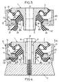
- the anti-vibration support is inserted and positioned in hole 13 so that, on the one hand, the face external of the frustoconical part 18 of the body of the frame outside 4 comes to bear in one direction substantially radial, against the complementary internal face 16 of the peripheral edge 15, and that, on the other hand, the edge 19 of the outer frame 4 rests, in one direction substantially vertical, on a complementary face 25 of the peripheral edge 15 which is adjacent to face 16.
- the legs 21 and the two bosses 24 extend downwards, beyond the edge 15 of orifice 13, the anti-vibration support being oriented so that the bosses 24 are located respectively in correspondence with notches 17 of the rim 15.
- the legs 21 are then folded outwards of the frustoconical part 18, in a direction substantially radial, so that the legs 21 are supported directly against the underside 26 of the flange 15.
- the elastomeric walls 22, which are integral respectively of two of the legs 21, are also folded under the rim 15, causing them to bosses 24, each boss 24 then being clipped respectively in the notch 17 associated therewith.
- the bosses 24 each have a shaped spout 27 to come and engage over an inner rim 17a of the notch 17 associated therewith.
- the bosses 24 are adapted to abut against the upper part 7a of the motor 7 (or against another buttress secured to the motor 7), and thus make it possible in particular to limit the displacement of the internal reinforcement 1 upwards, that is to say in a first sense 30 of the direction of vibration Z.
- the elastomer body 5 further comprises two other bosses 28 which are diametrically opposite with respect to the Z axis, and which extend respectively, from the peripheral edge upper 3 of the inner frame 1, towards the extensions 20 of the edge 19 of the outer frame 4, substantially along the Z axis.
- These bosses 28 are adapted to abut respectively against said extensions 20, in order to limit in particular the displacement of the inner frame 1 downward, that is to say in a second sense 31 of the direction of vibration Z.
- the elastomer body 5 also has two other bosses 29 which are diametrically opposed by relative to the upper peripheral edge 3 of the reinforcement interior 1 and which extend respectively from the bosses 28, in a substantially radial direction, towards the wall 14 of the orifice 13. These bosses 29 are adapted to abut respectively against said wall, in order to limit in particular the lateral displacement of the reinforcement interior 1 to console 10.
Landscapes
- Engineering & Computer Science (AREA)
- General Engineering & Computer Science (AREA)
- Mechanical Engineering (AREA)
- Health & Medical Sciences (AREA)
- Child & Adolescent Psychology (AREA)
- Vibration Prevention Devices (AREA)
- Combined Devices Of Dampers And Springs (AREA)
- Springs (AREA)
- Arrangement Or Mounting Of Propulsion Units For Vehicles (AREA)
Claims (9)
- Schwingungsdämpfendes Lager zur Anordnung zwischen einem ersten und einem zweiten steifen Element, um Schwingungen zwischen diesen beiden Elementen gemäß zumindest einer Schwingungsrichtung (Z) zu dämpfen, wobei das Lager folgendes aufweist:dadurch gekennzeichnet, dass der äußere Beschlag (4) einen mittleren Bereich (18) aufweist, der gegen die ringförmige Rippe (15) in zumindest einer im Wesentlichen radialen Richtung anliegt, und zumindest einen Fortsatz (21), der bezüglich des mittleren Bereichs (18) des äußeren Beschlags (4) nach außen geknickt und mit dem Vorsprung (24) verbunden ist, wobei sich der geknickte Fortsatz (21) und der Vorsprung (24) zu der ersten axialen Fläche der ringförmigen Rippe (15) hin weisend erstrecken, und wobei zumindest der Fortsatz (21) gegen die erste axiale Fläche anliegt, um den äußeren Beschlag (4) fest mit dem Vereinigungselement (10) zu vereinigen.zwei steife Beschläge, und zwar einen inneren (1) und einen äußeren (4), die dazu ausgestaltet sind, mit jeweils einem der beiden zu vereinigenden steifen Element verbunden zu werden, wobei der äußere Beschlag eine ringförmige Gestalt hat, die im Wesentlichen auf einer Achse zentriert ist, die parallel zu der besagten Schwingungsrichtung (Z) ist, und den inneren Beschlag (1) umgibt;einen Elastomerkörper (5), der die beiden steifen Beschläge untereinander verbindet und der eine erste Gruppe von Vorsprüngen mit zumindest einem Vorsprung (24) aufweist, welcher Vorsprung sich in einem ersten Sinn (31) gemäß der Schwingungsrichtung (Z) von dem äußeren Beschlag (4) aus erstreckt, wobei dieser Vorsprung (24) dazu ausgestaltet ist, gegen einen Anschlag anzustoßen, der mit dem ersten steifen Element verbunden ist, um die Verschiebung des inneren Beschlags (1) in der Schwingungsrichtung (Z) gemäß einem zweiten Sinn (30) zu begrenzen, der dem ersten Sinn (31) entgegengesetzt ist;und ein steifes Vereinigungselement (10), das eine innere ringförmige Rippe (15) aufweist, die eine Durchgangsöffnung (13) begrenzt, in welcher der äußere Beschlag (4) eingreift, wobei der äußere Beschlag (4) im ersten Sinn (31) der Schwingungsrichtung (Z) gegen die ringförmige Rippe (15) anliegt, wobei die ringförmige Rippe (15) eine erste axiale Fläche aufweist, die in dem ersten Sinn (31) orientiert ist, und wobei das Vereinigungselement (10) Vereinigungsmittel aufweist, die dazu bestimmt sind, an dem zweiten steifen Element angebracht zu werden,
- Schwingungsdämpfendes Lager gemäß Anspruch 1, bei welchem der Vorsprung (24) der ersten Gruppe mit dem dazugehörigen Fortsatz (21) des äußeren Beschlags (4) über eine schmale Wand (22) aus Elastomer verbunden ist, die einstückig mit dem Elastomerkörper (5) ausgeformt ist, wobei die schmale Wand (22) teilweise mit dem entsprechenden Fortsatz (21) und mit dem entsprechenden Vorsprung (24) verbunden ist.
- Schwingungsdämpfendes Lager gemäß den Ansprüchen 1 und 2, bei welchem jeder Vorsprung (24) der ersten Gruppe die Form einer dicken Zunge aus Elastomer hat, die mit dem Rest des Elastomerkörpers (5) über einen verdünnten flexiblen Bereich (24a) verbunden ist, und zwar so, dass die Zunge in der radialen Richtung schwenken kann, und wobei die schmale Wand aus Elastomer (22) mit der Zunge in zumindest einem Punkt verbunden ist, der von dem verdünnten Bereich (24a) beabstandet ist.
- Schwingungsdämpfendes Lager gemäß einem der vorangehenden Ansprüche, bei welchem jeder Vorsprung (24) der ersten Gruppe Clip-Mittel (27) aufweist, die dazu geeignet sind, mit komplementären Clip-Mitteln (17a) zusammenzuwirken, die mit der ringförmigen Rippe (15) des Vereinigungselements (10) verbunden sind, um den Vorsprung (24) unter der ringförmigen Rippe (15) zu halten.
- Schwingungsdämpfendes Lager gemäß einem der vorangehenden Ansprüche, bei welchem die ringförmige Rippe (15) des Vereinigungselements (10) eine zweite axiale Fläche hat, die der ersten axialen Fläche gegenüberliegt und die von dem äußeren Beschlag (4) bedeckt ist, wobei der äußere Beschlag (4) direkt und fest gegen die zweite Fläche anliegt und wobei jeder geknickte Fortsatz (21) des äußeren Beschlags (4) direkt und fest gegen die erste axiale Fläche der ringförmigen Rippe (15) des Vereinigungselements (10) anliegt, während der mittlere Bereich (18) des äußeren Beschlags (4) in radialer Richtung in direktem und festem Umfangskontakt gegen die Rippe (15) steht.
- Schwingungsdämpfendes Lager gemäß einem der vorangehenden Ansprüche, bei welchem der äußere Beschlag (4) durch ein geknicktes und geschnittenes Blech gebildet wird und an einem ersten Ende, das dem ersten steifen Element gegenüberliegt, mit einer äußeren Umfangskante (19) versehen ist und an einem zweiten Ende, das dem ersten Ende gegenüberliegt, mit zumindest zwei Fortsätzen (21), die einstückig mit dem äußeren Beschlag (4) ausgebildet sind und die sich im Wesentlichen diametral gegenüberliegen und die jeweils mit einem der beiden Vorsprünge (24) über Vereinigungsmittel verbunden sind, wobei diese Vorsprünge (24) einander ihrerseits bezüglich des äußeren Beschlags (4) diametral gegenüberliegen.
- Schwingungsdämpfendes Lager gemäß einem der vorangehenden Ansprüche, bei welchem der Elastomerkörper (5) eine zweite Gruppe von Vorsprüngen mit zumindest einem Vorsprung (28) beinhaltet, wobei jeder Vorsprung der zweiten Gruppe sich in dem ersten Sinn (31) der Schwingungsrichtung (Z) von dem inneren Beschlag (1) aus erstreckt, wobei dieser Vorsprung der zweiten Gruppe dazu ausgestaltet ist, gegen den äußeren Beschlag (4) anzuschlagen, um die Verschiebung des inneren Beschlags (1) in dem besagten ersten Sinn (31) zu beschränken.
- Schwingungsdämpfendes Lager gemäß einem der vorangehenden Ansprüche, bei welchem der Elastomerkörper (5) eine dritte Gruppe von Vorsprüngen mit zumindest einem Vorsprung (29) aufweist, wobei jeder Vorsprung der dritten Gruppe sich in einem ersten Sinn gemäß einer im Wesentlichen radialen Richtung von dem inneren Beschlag (1) aus erstreckt, wobei das Vereinigungselement (10) einen Anschlag (14) aufweist, der sich auf dem Niveau des Vorsprungs (29) der dritten Gruppe befindet und dazu ausgestaltet ist, mit letzterem zusammenzuwirken, um die seitliche Verschiebung des inneren Beschlags (1) in Richtung des Vereinigungselements (10) zu beschränken.
- Verfahren zur Herstellung eines schwingungsdämpfenden Lagers, das dazu bestimmt ist, zwischen einem ersten und einem zweiten steifen Element angeordnet zu werden, um Schwingungen zwischen diesen beiden Elementen gemäß zumindest einer Schwingungsrichtung (Z)zu dämpfen, wobei das Lager folgendes aufweist:dadurch gekennzeichnet, dass der äußere Beschlag (4) einen mittleren Bereich (18) aufweist, der gegen die ringförmige Rippe (15) in zumindest einer im Wesentlichen radialen Richtung anliegt, und zumindest einen Fortsatz (21), der bezüglich des mittleren Bereichs (18) des äußeren Beschlags (4) nach außen geknickt ist und mit dem Vorsprung (24) verbunden ist, wobei sich der geknickte Fortsatz (21) und der Vorsprung (24) zu der ersten axialen Fläche der ringförmigen Rippe (15) hin weisend erstrecken, und wobei zumindest der Fortsatz (21) gegen die erste axiale Fläche anliegt, um den äußeren Beschlag (4) fest mit dem Vereinigungselement (10) zu vereinigen, wobei das Verfahren die folgenden Schritte aufweist:zwei steife Beschläge, und zwar einen inneren (1) und einen äußeren (4), die dazu ausgestaltet sind, mit jeweils einem der beiden zu vereinigenden steifen Elemente verbunden zu werden, wobei der äußere Beschlag (4) eine ringförmige Gestalt hat, die im Wesentlichen zentriert auf einer Achse ist, die parallel zu der besagten Schwingungsrichtung (Z) ist, und den inneren Beschlag (1) umgibt;einen Elastomerkörper (5), der die beiden steifen Beschläge untereinander verbindet und der eine erste Gruppe von Vorsprüngen mit zumindest einem Vorsprung (24) aufweist, welcher Vorsprung (24) sich in einem ersten Sinn (31) gemäß der Schwingungsrichtung (Z) von dem äußeren Beschlag (4) aus erstreckt, wobei dieser Vorsprung (24) dazu ausgestaltet ist, gegen einen Anschlag anzustoßen, der mit dem ersten steifen Element verbunden ist, um die Verschiebung des inneren Beschlags (1) in der Schwingungsrichtung (Z) gemäß einem zweiten Sinn (30) zu begrenzen, der dem ersten Sinn (31) entgegengesetzt ist;und ein steifes Vereinigungselement (10), das eine innere ringförmige Rippe (15) aufweist, die eine Durchgangsöffnung (13) begrenzt, in welcher der äußere Beschlag (4) im Eingriff ist, wobei der äußere Beschlag (4) im ersten Sinn (31) der Schwingungsrichtung (Z) gegen die ringförmige Rippe (15) anliegt, wobei die ringförmige Rippe (15) eine erste axiale Fläche aufweist, die in dem ersten Sinn (31) orientiert ist, und wobei das Vereinigungselement (10) Vereinigungsmittel aufweist, die dazu bestimmt sind, an dem zweiten steifen Element angebracht zu werden,a) Ausformen des Elastomerkörpers (5) zwischen dem inneren Beschlag (1) und einem Vorprodukt des äußeren Beschlags, bei welchem sich jeder Fortsatz (21) im Wesentlichen axial in dem ersten Sinn (31) der Schwingungsrichtung (Z) erstreckt, so dass der Vorsprung (24) eine flexible Zunge bildet, die mit dem Fortsatz (21) verbunden ist, so dass der Elastomerkörper (5) daher mit dem inneren Beschlag (1) und dem Vorprodukt des äußeren Beschlags verbunden ist;b) Einpassen des Vorprodukts des äußeren Beschlags in die Öffnung (13) des Vereinigungselements (10), so dass der Fortsatz (21) des Vorprodukts des äußeren Beschlags und der Vorsprung (24) sich jenseits der ringförmigen Rippe (15) des Vereinigungselements (10) in dem ersten Sinn (31) der Schwingungsrichtung (Z) befinden; undc) Zurückfalten des Fortsatzes des Vorprodukts des äußeren Beschlags gegen die erste axiale Fläche der ringförmigen Rippe (15) des Vereinigungselements (10), wodurch der äußere Beschlag (4) ausgeformt wird, wobei gleichzeitig der Vorsprung (24) mitgenommen wird, um ihn unter der ringförmigen Rippe (15) des Vereinigungselements (10) zu positionieren.
Applications Claiming Priority (2)
| Application Number | Priority Date | Filing Date | Title |
|---|---|---|---|
| FR9901364A FR2789464B1 (fr) | 1999-02-05 | 1999-02-05 | Support antivibratoire et son procede de fabrication |
| FR9901364 | 1999-02-05 |
Publications (2)
| Publication Number | Publication Date |
|---|---|
| EP1026420A1 EP1026420A1 (de) | 2000-08-09 |
| EP1026420B1 true EP1026420B1 (de) | 2003-08-06 |
Family
ID=9541652
Family Applications (1)
| Application Number | Title | Priority Date | Filing Date |
|---|---|---|---|
| EP20000400277 Expired - Lifetime EP1026420B1 (de) | 1999-02-05 | 2000-02-02 | Schwingungsdämpfendes Lager und Verfahren zur Herstellung |
Country Status (6)
| Country | Link |
|---|---|
| EP (1) | EP1026420B1 (de) |
| AR (1) | AR022473A1 (de) |
| BR (1) | BR0000317A (de) |
| DE (1) | DE60004277T2 (de) |
| ES (1) | ES2204461T3 (de) |
| FR (1) | FR2789464B1 (de) |
Cited By (1)
| Publication number | Priority date | Publication date | Assignee | Title |
|---|---|---|---|---|
| CN107429781A (zh) * | 2015-03-31 | 2017-12-01 | 株式会社普利司通 | 隔振装置 |
Families Citing this family (10)
| Publication number | Priority date | Publication date | Assignee | Title |
|---|---|---|---|---|
| FR2829208B1 (fr) | 2001-09-05 | 2003-12-05 | Hutchinson | Ensemble anti-vibratoire et support anti-vibratoire faisant partie de cet ensemble |
| DE102007014541A1 (de) * | 2007-03-27 | 2008-10-30 | Contitech Vibration Control Gmbh | Elastisches Lager |
| FR2920210B1 (fr) * | 2007-08-20 | 2013-04-26 | Aircelle Sa | Amortisseur de vibrations pour nacelle d'aeronef |
| FR2947024B1 (fr) * | 2009-06-17 | 2011-06-10 | Hutchinson | Support antivibratoire a limitation de mouvement. |
| RU2479764C1 (ru) * | 2011-10-25 | 2013-04-20 | Федеральное государственное унитарное предприятие "Научно-производственное предприятие "Прогресс" (ФГУП "НПП "Прогресс") | Виброизолирующая опора |
| RU2493452C2 (ru) * | 2011-11-30 | 2013-09-20 | Евгений Иванович Андряков | Виброизолирующая опора силового агрегата |
| DE102014220291A1 (de) | 2014-10-07 | 2016-05-25 | Contitech Vibration Control Gmbh | Lagerung für eine Fahrerkabine eines Fahrzeuges |
| DE102014222817B4 (de) * | 2014-11-07 | 2024-04-25 | Volkswagen Aktiengesellschaft | Entkopplungselement sowie Kraftfahrzeug mit zumindest einem derartigen Entkopplungselement |
| GB201805838D0 (en) * | 2018-04-09 | 2018-05-23 | Dtr Vms Ltd | Bush |
| DE102018132558A1 (de) * | 2018-12-17 | 2020-06-18 | Bayerische Motoren Werke Aktiengesellschaft | Elastomerlager zur Anbringung eines Aggregats im Fahrzeug |
Family Cites Families (5)
| Publication number | Priority date | Publication date | Assignee | Title |
|---|---|---|---|---|
| US3479081A (en) * | 1968-04-22 | 1969-11-18 | Gen Motors Corp | Body mount |
| GB2062804B (en) * | 1979-11-10 | 1983-06-29 | Dunlop Ltd | Resilient mountings |
| GB8619240D0 (en) * | 1986-08-06 | 1986-09-17 | Dunlop Ltd | Elastomeric mounting |
| DE4011827A1 (de) * | 1990-04-12 | 1991-10-17 | Daimler Benz Ag | Abstuetzlager |
| US5310276A (en) * | 1992-12-21 | 1994-05-10 | Hutchinson | Connection device between two mechanical components |
-
1999
- 1999-02-05 FR FR9901364A patent/FR2789464B1/fr not_active Expired - Lifetime
-
2000
- 2000-02-01 AR ARP000100434 patent/AR022473A1/es active IP Right Grant
- 2000-02-02 ES ES00400277T patent/ES2204461T3/es not_active Expired - Lifetime
- 2000-02-02 EP EP20000400277 patent/EP1026420B1/de not_active Expired - Lifetime
- 2000-02-02 DE DE2000604277 patent/DE60004277T2/de not_active Expired - Lifetime
- 2000-02-07 BR BR0000317A patent/BR0000317A/pt not_active IP Right Cessation
Cited By (3)
| Publication number | Priority date | Publication date | Assignee | Title |
|---|---|---|---|---|
| CN107429781A (zh) * | 2015-03-31 | 2017-12-01 | 株式会社普利司通 | 隔振装置 |
| US10316925B2 (en) | 2015-03-31 | 2019-06-11 | Bridgestone Corporation | Vibration damping device |
| CN107429781B (zh) * | 2015-03-31 | 2019-07-09 | 株式会社普利司通 | 隔振装置 |
Also Published As
| Publication number | Publication date |
|---|---|
| DE60004277T2 (de) | 2004-06-24 |
| DE60004277D1 (de) | 2003-09-11 |
| FR2789464B1 (fr) | 2001-04-13 |
| ES2204461T3 (es) | 2004-05-01 |
| EP1026420A1 (de) | 2000-08-09 |
| AR022473A1 (es) | 2002-09-04 |
| BR0000317A (pt) | 2000-10-10 |
| FR2789464A1 (fr) | 2000-08-11 |
Similar Documents
| Publication | Publication Date | Title |
|---|---|---|
| EP1026420B1 (de) | Schwingungsdämpfendes Lager und Verfahren zur Herstellung | |
| EP1217249B1 (de) | Schwingungsdämpfendes Lager und Kraftfahrzeug mit einem solchen Lager | |
| EP0757007A1 (de) | Befestigungsring mit Doppelindexiervorrichtung | |
| EP1390639B1 (de) | Antischwingungslager und methode zur herstellung solcher | |
| FR2896842A1 (fr) | Support antivibratoire hydraulique et son procede de fabrication | |
| EP4370408A1 (de) | Aerodynamischer deflektor zur befestigung am unterboden einer kraftfahrzeugkarosserie mit vorrückhaltemitteln | |
| EP2113676A1 (de) | Schwingungsdämpfungsvorrichtung, System mit einer solchen Vorrichtung und Herstellungsverfahren | |
| EP1107432B1 (de) | Einrichtung zum Halten eines Elektromotors, insbesondere für Kraftfahrzeugausstattung | |
| EP2282076B1 (de) | Schwingungsdämpfervorrichtung für ein Fahrzeug, und eine solche Vorrichtung umfassendes Fahrzeug | |
| EP1309409B1 (de) | Befestigungselement für eine abgabevorrichtung | |
| EP1697183A1 (de) | Anordnung zum führen einer antriebswelle für einen wischmechanismus , die ein einziehen der antriebswelle bei einem aufprall ermöglicht | |
| FR2796998A1 (fr) | Dispositif pour la fixation d'un ecran acoustique sur un moteur | |
| WO2015090986A1 (fr) | Traverse de planche de bord avec supports latéraux compacts collés | |
| EP1059466B1 (de) | Schwingungsdämpfer mit unausdehnbarem Kabelbegrenzer | |
| FR2783368A1 (fr) | Dispositif perfectionne de fixation elastique d'un moteur electrique a bague, notamment pour vehicule automobile | |
| EP1293701B1 (de) | Schwingungsdämpfendes Lager und Schwingungsdämpfungseinrichtung mit solchem Lager | |
| EP4313651B1 (de) | Auspuffstrangaufhängung eines fahrzeugs | |
| EP1759122A1 (de) | Anordnung zur befestigung einer kraftfahrzeugkomponente | |
| EP0845617B1 (de) | Schwingungsdämpfendes Lager und Kraftfahrzeug mit solchem Lager | |
| EP1607271B1 (de) | Durchführungsvorrichtung für dünnes Blech | |
| FR2851801A1 (fr) | Dispositif de montage d'une structure rotative sur un axe | |
| WO2008139084A2 (fr) | Barre de maintien de charge pour vehicule utilitaire et ensemble de barres pour maintien de charge | |
| FR2808854A1 (fr) | Support antivibratoire, et vehicule comportant un tel support | |
| EP2322406B1 (de) | Vereinfachte Positionsverriegelungsvorrichtung einer verstellbaren Lenksäule eines Kraftfahrzeugs | |
| FR2820723A3 (fr) | Organe de fixation de dispositif de distribution de produit fluide sur un col de recipient |
Legal Events
| Date | Code | Title | Description |
|---|---|---|---|
| PUAI | Public reference made under article 153(3) epc to a published international application that has entered the european phase |
Free format text: ORIGINAL CODE: 0009012 |
|
| AK | Designated contracting states |
Kind code of ref document: A1 Designated state(s): DE ES GB IT |
|
| AX | Request for extension of the european patent |
Free format text: AL;LT;LV;MK;RO;SI |
|
| 17P | Request for examination filed |
Effective date: 20001117 |
|
| AKX | Designation fees paid |
Free format text: DE ES GB IT |
|
| GRAH | Despatch of communication of intention to grant a patent |
Free format text: ORIGINAL CODE: EPIDOS IGRA |
|
| GRAH | Despatch of communication of intention to grant a patent |
Free format text: ORIGINAL CODE: EPIDOS IGRA |
|
| GRAA | (expected) grant |
Free format text: ORIGINAL CODE: 0009210 |
|
| AK | Designated contracting states |
Designated state(s): DE ES GB IT |
|
| REG | Reference to a national code |
Ref country code: GB Ref legal event code: FG4D Free format text: NOT ENGLISH |
|
| REF | Corresponds to: |
Ref document number: 60004277 Country of ref document: DE Date of ref document: 20030911 Kind code of ref document: P |
|
| GBT | Gb: translation of ep patent filed (gb section 77(6)(a)/1977) |
Effective date: 20031205 |
|
| REG | Reference to a national code |
Ref country code: ES Ref legal event code: FG2A Ref document number: 2204461 Country of ref document: ES Kind code of ref document: T3 |
|
| PLBE | No opposition filed within time limit |
Free format text: ORIGINAL CODE: 0009261 |
|
| STAA | Information on the status of an ep patent application or granted ep patent |
Free format text: STATUS: NO OPPOSITION FILED WITHIN TIME LIMIT |
|
| 26N | No opposition filed |
Effective date: 20040507 |
|
| PGFP | Annual fee paid to national office [announced via postgrant information from national office to epo] |
Ref country code: GB Payment date: 20140219 Year of fee payment: 15 |
|
| GBPC | Gb: european patent ceased through non-payment of renewal fee |
Effective date: 20150202 |
|
| PG25 | Lapsed in a contracting state [announced via postgrant information from national office to epo] |
Ref country code: GB Free format text: LAPSE BECAUSE OF NON-PAYMENT OF DUE FEES Effective date: 20150202 |
|
| PGFP | Annual fee paid to national office [announced via postgrant information from national office to epo] |
Ref country code: DE Payment date: 20190211 Year of fee payment: 20 Ref country code: IT Payment date: 20190208 Year of fee payment: 20 Ref country code: ES Payment date: 20190321 Year of fee payment: 20 |
|
| REG | Reference to a national code |
Ref country code: DE Ref legal event code: R071 Ref document number: 60004277 Country of ref document: DE |
|
| REG | Reference to a national code |
Ref country code: ES Ref legal event code: FD2A Effective date: 20200721 |
|
| PG25 | Lapsed in a contracting state [announced via postgrant information from national office to epo] |
Ref country code: ES Free format text: LAPSE BECAUSE OF EXPIRATION OF PROTECTION Effective date: 20200203 |