EP1026432A2 - Coupling device for pipelines - Google Patents
Coupling device for pipelines Download PDFInfo
- Publication number
- EP1026432A2 EP1026432A2 EP99122379A EP99122379A EP1026432A2 EP 1026432 A2 EP1026432 A2 EP 1026432A2 EP 99122379 A EP99122379 A EP 99122379A EP 99122379 A EP99122379 A EP 99122379A EP 1026432 A2 EP1026432 A2 EP 1026432A2
- Authority
- EP
- European Patent Office
- Prior art keywords
- seal
- coupling device
- connection element
- connection
- coupling
- Prior art date
- Legal status (The legal status is an assumption and is not a legal conclusion. Google has not performed a legal analysis and makes no representation as to the accuracy of the status listed.)
- Granted
Links
Images
Classifications
-
- F—MECHANICAL ENGINEERING; LIGHTING; HEATING; WEAPONS; BLASTING
- F16—ENGINEERING ELEMENTS AND UNITS; GENERAL MEASURES FOR PRODUCING AND MAINTAINING EFFECTIVE FUNCTIONING OF MACHINES OR INSTALLATIONS; THERMAL INSULATION IN GENERAL
- F16L—PIPES; JOINTS OR FITTINGS FOR PIPES; SUPPORTS FOR PIPES, CABLES OR PROTECTIVE TUBING; MEANS FOR THERMAL INSULATION IN GENERAL
- F16L19/00—Joints in which sealing surfaces are pressed together by means of a member, e.g. a swivel nut, screwed on, or into, one of the joint parts
- F16L19/02—Pipe ends provided with collars or flanges, integral with the pipe or not, pressed together by a screwed member
- F16L19/0212—Pipe ends provided with collars or flanges, integral with the pipe or not, pressed together by a screwed member using specially adapted sealing means
Definitions
- the invention relates to a coupling device for Pipes according to the preamble of claim 1.
- a such by the company Südmo Schleicher AG under the Description "Aseptic screw connection with O-ring seal"
- Known coupling device has a first connector with a seat for a seal against the one the second connection piece lies flat with its end face.
- the flat contact surface of the second connector against the seal there are undercuts the seal and the second connector, in which Can accumulate contaminants.
- CIP or SIP applications is the known coupling device critical.
- the known coupling device on the peripheral surface of the first connector External thread on that with an internal thread on the second Interacting connector If the access is difficult This is the type of connection point within machines Connection is a hindrance because of screwing the two Fittings several turns of the second With a corresponding manual grip required are.
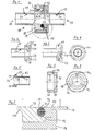
- the coupling device 10 shown in FIG. 1 is Part of a line for a flowing medium in a aseptic packaging machine.
- the Coupling device 10 has four components, a first one Connector 11, an O-ring shaped seal 12, a second connector 13 and a coupling piece 14.
- About the free ends 16, 17 of the two connectors 11, 13 can Hoses, not shown, are pushed over the different areas or institutions of Connect the packaging machine to one another. It is too possible to free ends 16, 17 with rigid pipe pieces couple.
- the first tubular connector 11 has one flange-shaped circumferential collar 18, on the outer Shell or peripheral surface 19 at least one, in Embodiment, however, evenly over the circumference distributed three groove-shaped guideways 21 are formed.
- the guideways 21 are part of a Bayonet connection 22. It is particularly advantageous that Slope of the guideways 21 in their end regions 20 something again, e.g. 0.1mm, to be provided in the opposite direction.
- in the inner area of one end face 23 is a first Recording 24 for the annular seal 12th educated.
- the first receptacle 24 takes the seal 12 in whose area is form-fitting, the first receptacle 24 however, only encompasses part of the seal 12.
- the seal 12 inserted into the first receptacle 24 projects beyond the end face 23, and the inner wall 26 of the first connector 11 extends with its peripheral edge 27 not up to the level of the end face 23.
- the receptacle 24 prefers a slightly smaller outside diameter than that Seal 12 so that the seal 12 is clamped in the receptacle 24 is held.
- the second tubular connector 13 has at its that first connector 11 facing end a flange circumferential edge 29.
- the seal facing 12 End face 30 is concave in the area of the seal 12 trained so that they have a second receptacle 31 for form-fitting embracing the seal 12 forms. It sticks out the inner peripheral edge 32 of the second receptacle 31 to close to the peripheral edge 27 of the first receptacle 24 approach, the one in the connecting area of the two Connections 11, 13 arranged between the edges 27, 32 Bead 33 of the seal 12 due to the compression of the Seal 12 is formed and in the interior of the Coupling device 10 partially protrudes without between the bead 33 and the two connecting pieces 11, 13 Cavities or undercuts are formed.
- the inner walls 26, 34 are the two connectors 11, 13 in their connection area each provided with a circumferential bevel 36, 37, so that the flow cross section in the area of the seal 12 through the bead 33 of the seal 12 does not have the in the Areas without bevels 36, 37 existing measure of Connectors 11, 13 is reduced.
- the annular coupling piece 14 has three areas 38, 39, 40 with different inner diameters, of which the area 38 the smallest inside diameter and the Area 40 has the largest inner diameter.
- the central area 39 has one Inner diameter that is minimally larger than that Outer diameter of the edge 29 of the second connector 13 and its width.
- Area 38 has one Inner diameter that is slightly larger than that Outside diameter of the second connector 13 in its borderless area.
- the outer contour of the Coupling piece 14 formed as a hexagon to the Coupling piece 14 alternatively with one To be able to mount a wrench.
- To rotate coupling piece 14 by a small angle to a fixed connection by means of the bayonet connection 22 to manufacture.
- the latching of the retaining pins 42 in the end regions 20 noticeable and audible.
Landscapes
- Engineering & Computer Science (AREA)
- General Engineering & Computer Science (AREA)
- Mechanical Engineering (AREA)
- Quick-Acting Or Multi-Walled Pipe Joints (AREA)
- Surface Acoustic Wave Elements And Circuit Networks Thereof (AREA)
Abstract
Eine Kupplungseinrichtung (10) für Rohrleitungen weist zwei
Anschlußstücke (11, 13), eine Dichtung (12) sowie ein
Kupplungsstück (14) auf. Die Dichtung (12) ist in jeweils
einer in jedem Anschlußstück (11, 13) ausgebildeten Aufnahme
(24, 31) zumindest im Bereich der Innenwandungen (26, 34)
formschlüssig aufgenommen. Ferner ist an dem ersten
Anschlußstück (11) und dem Kupplungsstück (14) eine
Bajonettverbindung (22) ausgebildet, die eine einfache
Montage der Kupplungseinrichtung (10) ermöglicht. Die
erfindungsgemäße Kupplungseinrichtung (10) ist besonders
einfach reinig- bzw. sterilisierbar und daher besonders für
den Einsatz in aseptisch arbeitenden Verpackungsmaschinen
geeignet.

Description
Die Erfindung betrifft eine Kupplungseinrichtung für Rohrleitungen nach dem Oberbegriff des Anspruchs 1. Eine derartige, von der Firma Südmo Schleicher AG unter der Bezeichnung "Aseptikverschraubung mit O-Ring-Dichtung" bekannte Kupplungseinrichtung weist ein erstes Anschlußstück mit einer Aufnahme für eine Dichtung auf, gegen die ein zweites Anschlußstück mit seiner Stirnseite flächig anliegt. Infolge der ebenen Anlagefläche des zweiten Anschlußstücks gegen die Dichtung kommt es zu Hinterschneidungen zwischen der Dichtung und dem zweiten Anschlußstück, in denen sich Verunreinigungen ansammeln können. Insbesondere für den Fall, daß die Kupplungseinrichtung im eingebauten Zustand reinig- bzw. sterilisierbar sein soll (sog. CIP- bzw. SIP-Anwendungen), ist die bekannte Kupplungseinrichtung daher kritisch. Weiterhin weist die bekannte Kupplungseinrichtung an der Umfangsfläche des ersten Anschlußstücks ein Außengewinde auf, das mit einem Innengewinde am zweiten Anschlußstück zusammenwirkt. Bei schwer zugänglichen Verbindungsorten innerhalb von Maschinen ist diese Art der Verbindung hinderlich, da zum Verschrauben der beiden Anschlußstücke mehrere Umdrehungen des zweiten Anschlußstücks mit einem entsprechenden manuellen Umgreifen erforderlich sind.The invention relates to a coupling device for Pipes according to the preamble of claim 1. A such, by the company Südmo Schleicher AG under the Description "Aseptic screw connection with O-ring seal" Known coupling device has a first connector with a seat for a seal against the one the second connection piece lies flat with its end face. As a result of the flat contact surface of the second connector against the seal there are undercuts the seal and the second connector, in which Can accumulate contaminants. Especially for the Case that the coupling device in the installed state should be able to be cleaned or sterilized (so-called CIP or SIP applications), is the known coupling device critical. Furthermore, the known coupling device on the peripheral surface of the first connector External thread on that with an internal thread on the second Interacting connector. If the access is difficult This is the type of connection point within machines Connection is a hindrance because of screwing the two Fittings several turns of the second With a corresponding manual grip required are.
Die erfindungsgemäße Kupplungseinrichtung für Rohrleitungen mit den kennzeichnenden Merkmalen des Anspruchs 1 hat demgegenüber den Vorteil, daß an der fertig montierten Kupplungseinrichtung Hinterschneidungen oder Hohlräume zwischen der Dichtung und den Anschlußstücken vermieden werden. Dadurch läßt sich eine einfache Reinig- und Sterilisierbarkeit der Kupplungseinrichtung ermöglichen.The coupling device for pipes according to the invention with the characterizing features of claim 1 in contrast, the advantage that on the fully assembled Coupling device undercuts or cavities avoided between the seal and the fittings become. This makes it easy to clean and Enable sterilization of the coupling device.
Weitere vorteilhafte Weiterbildungen der erfindungsgemäßen Kupplungseinrichtung für Rohrleitungen sind in den Unteransprüchen angegeben. Durch die Ausbildung eines Bajonettverschlusses an den beiden Anschlußstücken wird eine einfache Montierbarkeit erzielt, bei der kein Umgreifen mehr nötig ist, um die beiden Anschlußstücke vollständig miteinander zu verbinden. Um zu verhindern, daß die Dichtung bei noch nicht montiertem zweiten Anschlußstück aus seiner Aufnahme im ersten Anschlußstück herausfällt ist es vorteilhaft, wenn die Aufnahme im ersten Anschlußstück durch eine entsprechende Formgebung die Dichtung durch Klemmen hält. Um zu verhindern, daß es infolge eines aus der Verbindungsstelle der beiden Anschlußstücke herausragenden Dichtungsabschnitts zu einer Strömungsverengung kommt, ist es bevorzugt vorgesehen, die Innenwandungen der Anschlußstücke in Ihrem Verbindungsbereich aufzuweiten. Further advantageous developments of the invention Coupling device for pipes are in the Subclaims specified. By training a Bayonet lock on the two connectors becomes one Easy to assemble achieved, with no more reaching around is necessary to complete the two fittings connect with each other. To prevent the seal if the second connector has not yet been installed from its Recording in the first connector falls out advantageous if the inclusion in the first connector an appropriate shaping of the seal by clamping holds. To prevent it as a result of any of the Connection point of the two connecting pieces protrude Sealing section comes to a flow restriction it preferably provided the inner walls of the Expand connectors in your connection area.
Ein Ausführungsbeispiel der Erfindung ist in der Zeichnung
dargestellt und wird nachfolgend näher erläutert. Es zeigen:
Die in der Figur 1 dargestellte Kupplungseinrichtung 10 ist
Bestandteil einer Leitung für ein strömendes Medium in einer
aseptisch arbeitenden Verpackungsmaschine. Die
Kupplungseinrichtung 10 weist vier Bauteile auf, ein erstes
Anschlußstück 11, eine O-Ring förmige Dichtung 12, ein
zweites Anschlußstück 13 und ein Kupplungsstück 14. Über die
freien Enden 16, 17 der beiden Anschlußstücke 11, 13 können
nicht dargestellte Schläuche übergeschoben werden, die die
unterschiedlichen Bereiche bzw. Einrichtungen der
Verpackungsmaschine miteinander verbinden. Auch ist es
möglich, die freien Enden 16, 17 mit starren Rohrstücken zu
koppeln.The coupling device 10 shown in FIG. 1 is
Part of a line for a flowing medium in a
aseptic packaging machine. The
Coupling device 10 has four components, a first one
Das erste rohrförmige Anschlußstück 11 hat einen
flanschförmig umlaufenden Kragen 18, an dessen äußerer
Mantel- bzw. Umfangsfläche 19 wenigstens ein, im
Ausführungsbeispiel jedoch über den Umfang gleichmäßig
verteilt drei nutförmige Führungsbahnen 21 ausgebildet sind.
Die Führungsbahnen 21 sind Bestandteil einer
Bajonettverbindung 22. Besonders vorteilhaft ist es, die
Steigung der Führungsbahnen 21 in ihren Endbereichen 20
wieder etwas, z.B. 0,1mm, in Gegenrichtung zu versehen. Im
inneren Bereich der einen Stirnfläche 23 ist eine erste
Aufnahme 24 für die kreisringförmige Dichtung 12
ausgebildet. Die erste Aufnahme 24 nimmt die Dichtung 12 in
deren Bereich formschlüssig auf, wobei die erste Aufnahme 24
jedoch nur einen Teil der Dichtung 12 umgreift. Insbesondere
ragt die in die erste Aufnahme 24 eingelegte Dichtung 12
über die Stirnfläche 23 hinaus, und die Innenwandung 26 des
ersten Anschlußstücks 11 reicht mit ihrer umlaufenden Kante
27 nicht bis in Höhe der Stirnfläche 23. Um ein Verlieren
der Dichtung 12 zu verhindern, weist die Aufnahme 24
bevorzugt einen etwas kleineren Außendurchmesser auf als die
Dichtung 12, so daß die Dichtung 12 klemmend in der Aufnahme
24 gehalten ist.The first
Das zweite rohrförmige Anschlußstück 13 weist an seinem dem
ersten Anschlußstück 11 zugewandten Ende einen flanschförmig
umlaufenden Rand 29 auf. Die der Dichtung 12 zugewandte
Stirnfläche 30 ist im Bereich der Dichtung 12 konkav
ausgebildet, so daß sie eine zweite Aufnahme 31 zum
formschlüssigen Umfassen der Dichtung 12 bildet. Dabei ragt
die innere umlaufende Kante 32 der zweiten Aufnahme 31 bis
nahe an die umlaufende Kante 27 der ersten Aufnahme 24
heran, wobei die im Verbindungsbereich der beiden
Anschlußstücke 11, 13 zwischen den Kanten 27, 32 angeordnete
Wulst 33 der Dichtung 12 infolge des Zusammendrückens der
Dichtung 12 entsteht und in den Innenbereich der
Kupplungseinrichtung 10 teilweise hineinragt, ohne daß
zwischen der Wulst 33 und den beiden Anschlußstücken 11, 13
Hohlräume oder Hinterschneidungen ausgebildet werden. Um zu
verhindern, daß die Wulst 33 der Dichtung 12 zu einer
Strömungsverengung für das durch die Kupplungseinrichtung 10
strömende Medium führt, sind die Innenwandungen 26, 34 der
beiden Anschlußstücke 11, 13 in deren Verbindungsbereich
jeweils mit einer umlaufenden Schräge 36, 37 versehen, so
daß der Strömungsquerschnitt im Bereich der Dichtung 12
durch die Wulst 33 der Dichtung 12 nicht über das in den
Bereichen ohne Schrägen 36, 37 vorhandene Maß der
Anschlußstücke 11, 13 reduziert ist.The second
Das ringförmige Kupplungsstück 14 weist drei Bereiche 38,
39, 40 mit unterschiedlichen Innendurchmessern auf, wovon
der Bereich 38 den kleinsten Innendurchmesser und der
Bereich 40 den größten Innendurchmesser aufweist.
In dem Bereich 40 sind in entsprechenden Ausnehmungen
entsprechend der Führungsbahnen 21 drei Haltestifte 42
eingesetzt, die in das Innere des Kupplungsstücks 14
hineinragen, und die mit den Führungsbahnen 21
zusammenwirken und dabei die Bajonettverbindung 22
ausbilden. Der mittlere Bereich 39 hat einen
Innendurchmesser, der minimal größer ist als der
Außendurchmesser des Randes 29 des zweiten Anschlußstücks 13
sowie dessen Breite aufweist. Der Bereich 38 hat einen
Innendurchmesser, der geringfügig größer ist als der
Außendurchmesser des zweiten Anschlußstücks 13 in dessen
randfreiem Bereich. Mit der beschriebenen Ausbildung des
Kupplungsstücks 14 kann dieses auf das zweite Anschlußstück
13 in Art einer Überwurfmutter montiert werden (Figuren 1
und 8). Im Ausführungsbeispiel ist die Außenkontur des
Kupplungsstücks 14 als Sechskant ausgebildet, um das
Kupplungsstück 14 alternativ auch mit einem
Schraubenschlüssel montieren zu können. Beim Zusammenfügen
der beiden Anschlußstücke 11, 13 genügt es, das
Kupplungsstück 14 um einen geringen Winkelbetrag zu drehen,
um mittels der Bajonettverbindung 22 eine feste Verbindung
herzustellen. Dabei wird durch die Ausbildung der
Führungsbahnen 21 mit ihren Endbereichen 20, die in
Gegenrichtung der ursprünglichen Steigung verläuft erreicht,
daß sich die Bajonettverbindung 21 unabsichtlich öffnet.
Außerdem ist so beim Montieren der Kupplungseinrichtung 10
das Einrasten der Haltestifte 42 in den Endbereichen 20
spür- und auch hörbar. Die durch das Zusammenfügen der
beiden Anschlußstücke 11, 13 infolge der Pressung
ausgebildete Wulst 33 der Dichtung 12 ist ein gewollter
Effekt, damit die Lücken zwischen den beiden Kanten 27 und
32 an den Innenwandungen 26, 34 geschlossen werden. Dadurch,
daß die ringförmige Dichtung 12 durch die beiden Aufnahmen
24, 31 nahezu vollständig umschlossen ist, kann die Dichtung
12 nur nach innen, unter Bildung der Wulst 33, ausweichen.The
Claims (5)
Applications Claiming Priority (2)
| Application Number | Priority Date | Filing Date | Title |
|---|---|---|---|
| DE19904164A DE19904164A1 (en) | 1999-02-03 | 1999-02-03 | Coupling device for pipes |
| DE19904164 | 1999-02-03 |
Publications (3)
| Publication Number | Publication Date |
|---|---|
| EP1026432A2 true EP1026432A2 (en) | 2000-08-09 |
| EP1026432A3 EP1026432A3 (en) | 2000-12-27 |
| EP1026432B1 EP1026432B1 (en) | 2006-07-12 |
Family
ID=7896189
Family Applications (1)
| Application Number | Title | Priority Date | Filing Date |
|---|---|---|---|
| EP99122379A Expired - Lifetime EP1026432B1 (en) | 1999-02-03 | 1999-11-10 | Coupling device for pipelines |
Country Status (4)
| Country | Link |
|---|---|
| EP (1) | EP1026432B1 (en) |
| AT (1) | ATE333065T1 (en) |
| DE (2) | DE19904164A1 (en) |
| DK (1) | DK1026432T3 (en) |
Cited By (3)
| Publication number | Priority date | Publication date | Assignee | Title |
|---|---|---|---|---|
| WO2001088424A1 (en) * | 2000-05-16 | 2001-11-22 | Neumo Gmbh + Co. Kg | Sealing system for media-carrying parts |
| WO2006128547A1 (en) * | 2005-06-03 | 2006-12-07 | Armaturenwerk Hötensleben GmbH | Pipe coupling |
| CN105431667A (en) * | 2013-03-15 | 2016-03-23 | 福斯管理公司 | Cleaning Accessories for Fluid Handling Equipment |
Family Cites Families (6)
| Publication number | Priority date | Publication date | Assignee | Title |
|---|---|---|---|---|
| CH534832A (en) * | 1971-12-20 | 1973-03-15 | Mueller Hans | Microbiological appts pipe-fitting - with quick connect/disconnect |
| DE7818046U1 (en) * | 1978-06-16 | 1979-01-11 | Holstein Und Kappert Gmbh, 4600 Dortmund | CONNECTING DEVICE FOR PIPELINES |
| DE2910684C2 (en) * | 1979-03-19 | 1981-10-01 | Otto Tuchenhagen GmbH & Co KG, 2059 Büchen | Detachable pipe or valve connection |
| DE3143369C2 (en) * | 1981-11-02 | 1985-02-28 | Leonhard Schleicher Südmo-Armaturenfabrik GmbH, 7081 Riesbürg | Aseptic tube fitting |
| AU3977095A (en) * | 1995-01-11 | 1996-07-31 | Bbs Systems | Pipe union for sterile purposes |
| IL131550A0 (en) * | 1997-02-24 | 2001-01-28 | Swagelok Co | Joint with thermal expansion area |
-
1999
- 1999-02-03 DE DE19904164A patent/DE19904164A1/en not_active Withdrawn
- 1999-11-10 EP EP99122379A patent/EP1026432B1/en not_active Expired - Lifetime
- 1999-11-10 DK DK99122379T patent/DK1026432T3/en active
- 1999-11-10 AT AT99122379T patent/ATE333065T1/en not_active IP Right Cessation
- 1999-11-10 DE DE59913662T patent/DE59913662D1/en not_active Expired - Lifetime
Cited By (3)
| Publication number | Priority date | Publication date | Assignee | Title |
|---|---|---|---|---|
| WO2001088424A1 (en) * | 2000-05-16 | 2001-11-22 | Neumo Gmbh + Co. Kg | Sealing system for media-carrying parts |
| WO2006128547A1 (en) * | 2005-06-03 | 2006-12-07 | Armaturenwerk Hötensleben GmbH | Pipe coupling |
| CN105431667A (en) * | 2013-03-15 | 2016-03-23 | 福斯管理公司 | Cleaning Accessories for Fluid Handling Equipment |
Also Published As
| Publication number | Publication date |
|---|---|
| DE59913662D1 (en) | 2006-08-24 |
| DE19904164A1 (en) | 2000-08-10 |
| EP1026432A3 (en) | 2000-12-27 |
| DK1026432T3 (en) | 2006-10-30 |
| EP1026432B1 (en) | 2006-07-12 |
| ATE333065T1 (en) | 2006-08-15 |
Similar Documents
| Publication | Publication Date | Title |
|---|---|---|
| DE4034803C2 (en) | ||
| DE69605937T2 (en) | QUICK COUPLING WITH CONCENTRIC CONFIGURATION | |
| DE69011769T2 (en) | Quick coupling. | |
| EP1697674A1 (en) | Plug connector for fluid conduits | |
| DE3246327A1 (en) | Device for connecting two pipe ends | |
| DE19747959A1 (en) | Connector | |
| EP0545037B1 (en) | Coupling device for two conducts, in particular for fuel conducts | |
| EP2334968B1 (en) | Locking coupling | |
| DE10155541A1 (en) | Fuel tank and its connection with a pipe | |
| EP1026432A2 (en) | Coupling device for pipelines | |
| EP4390207B1 (en) | Coupling part for a hydraulic coupling | |
| EP2460943B1 (en) | Flushing cistern | |
| WO2024042039A1 (en) | Fluid coupling, method for producing a fluid coupling, and fluid coupling arrangement | |
| DE4211959C2 (en) | ||
| EP3153757B1 (en) | Detachable plug connection for pipes | |
| DE19944247A1 (en) | Coupling termination for liquid lines e.g. for i.c. engine fuel injection system | |
| DE29920410U1 (en) | Flap with pipe adapter | |
| DE2634721A1 (en) | Liq. tap adaptor fitting - has coaxial inlet and outlet with valve between rotated to distribute flow | |
| DE4241817C2 (en) | Connection device for pipe and / or hose lines | |
| EP4001724B1 (en) | Connecting device for media-carrying components | |
| DE29707044U1 (en) | Connector for connecting a hose | |
| DE29805665U1 (en) | Pipe fitting | |
| DE29904740U1 (en) | Protection device for plug-in couplings on connecting lines | |
| DE102016223744B4 (en) | Brake system with a connecting element | |
| DE4418192A1 (en) | Adapter for taps |
Legal Events
| Date | Code | Title | Description |
|---|---|---|---|
| PUAI | Public reference made under article 153(3) epc to a published international application that has entered the european phase |
Free format text: ORIGINAL CODE: 0009012 |
|
| AK | Designated contracting states |
Kind code of ref document: A2 Designated state(s): AT BE CH CY DE DK ES FI FR GB GR IE IT LI LU MC NL PT SE |
|
| AX | Request for extension of the european patent |
Free format text: AL;LT;LV;MK;RO;SI |
|
| PUAL | Search report despatched |
Free format text: ORIGINAL CODE: 0009013 |
|
| AK | Designated contracting states |
Kind code of ref document: A3 Designated state(s): AT BE CH CY DE DK ES FI FR GB GR IE IT LI LU MC NL PT SE |
|
| AX | Request for extension of the european patent |
Free format text: AL;LT;LV;MK;RO;SI |
|
| RIC1 | Information provided on ipc code assigned before grant |
Free format text: 7F 16L 19/02 A, 7F 16L 23/22 B, 7F 16L 37/252 B |
|
| 17P | Request for examination filed |
Effective date: 20010627 |
|
| AKX | Designation fees paid |
Free format text: AT BE CH CY DE DK ES FI FR GB GR IE IT LI LU MC NL PT SE |
|
| GRAP | Despatch of communication of intention to grant a patent |
Free format text: ORIGINAL CODE: EPIDOSNIGR1 |
|
| GRAS | Grant fee paid |
Free format text: ORIGINAL CODE: EPIDOSNIGR3 |
|
| GRAA | (expected) grant |
Free format text: ORIGINAL CODE: 0009210 |
|
| AK | Designated contracting states |
Kind code of ref document: B1 Designated state(s): AT BE CH CY DE DK ES FI FR GB GR IE IT LI LU MC NL PT SE |
|
| PG25 | Lapsed in a contracting state [announced via postgrant information from national office to epo] |
Ref country code: NL Free format text: LAPSE BECAUSE OF FAILURE TO SUBMIT A TRANSLATION OF THE DESCRIPTION OR TO PAY THE FEE WITHIN THE PRESCRIBED TIME-LIMIT Effective date: 20060712 Ref country code: IT Free format text: LAPSE BECAUSE OF FAILURE TO SUBMIT A TRANSLATION OF THE DESCRIPTION OR TO PAY THE FEE WITHIN THE PRESCRIBED TIME-LIMIT;WARNING: LAPSES OF ITALIAN PATENTS WITH EFFECTIVE DATE BEFORE 2007 MAY HAVE OCCURRED AT ANY TIME BEFORE 2007. THE CORRECT EFFECTIVE DATE MAY BE DIFFERENT FROM THE ONE RECORDED. Effective date: 20060712 Ref country code: IE Free format text: LAPSE BECAUSE OF FAILURE TO SUBMIT A TRANSLATION OF THE DESCRIPTION OR TO PAY THE FEE WITHIN THE PRESCRIBED TIME-LIMIT Effective date: 20060712 Ref country code: FI Free format text: LAPSE BECAUSE OF FAILURE TO SUBMIT A TRANSLATION OF THE DESCRIPTION OR TO PAY THE FEE WITHIN THE PRESCRIBED TIME-LIMIT Effective date: 20060712 |
|
| REG | Reference to a national code |
Ref country code: GB Ref legal event code: FG4D Free format text: NOT ENGLISH |
|
| REG | Reference to a national code |
Ref country code: CH Ref legal event code: EP |
|
| REG | Reference to a national code |
Ref country code: CH Ref legal event code: NV Representative=s name: SCINTILLA AG, DIREKTION |
|
| REG | Reference to a national code |
Ref country code: IE Ref legal event code: FG4D Free format text: LANGUAGE OF EP DOCUMENT: GERMAN |
|
| REF | Corresponds to: |
Ref document number: 59913662 Country of ref document: DE Date of ref document: 20060824 Kind code of ref document: P |
|
| REG | Reference to a national code |
Ref country code: SE Ref legal event code: TRGR |
|
| PG25 | Lapsed in a contracting state [announced via postgrant information from national office to epo] |
Ref country code: ES Free format text: LAPSE BECAUSE OF FAILURE TO SUBMIT A TRANSLATION OF THE DESCRIPTION OR TO PAY THE FEE WITHIN THE PRESCRIBED TIME-LIMIT Effective date: 20061023 |
|
| REG | Reference to a national code |
Ref country code: DK Ref legal event code: T3 |
|
| GBT | Gb: translation of ep patent filed (gb section 77(6)(a)/1977) |
Effective date: 20061018 |
|
| PG25 | Lapsed in a contracting state [announced via postgrant information from national office to epo] |
Ref country code: MC Free format text: LAPSE BECAUSE OF NON-PAYMENT OF DUE FEES Effective date: 20061130 Ref country code: BE Free format text: LAPSE BECAUSE OF NON-PAYMENT OF DUE FEES Effective date: 20061130 |
|
| PG25 | Lapsed in a contracting state [announced via postgrant information from national office to epo] |
Ref country code: PT Free format text: LAPSE BECAUSE OF FAILURE TO SUBMIT A TRANSLATION OF THE DESCRIPTION OR TO PAY THE FEE WITHIN THE PRESCRIBED TIME-LIMIT Effective date: 20061212 |
|
| NLV1 | Nl: lapsed or annulled due to failure to fulfill the requirements of art. 29p and 29m of the patents act | ||
| ET | Fr: translation filed | ||
| PLBE | No opposition filed within time limit |
Free format text: ORIGINAL CODE: 0009261 |
|
| STAA | Information on the status of an ep patent application or granted ep patent |
Free format text: STATUS: NO OPPOSITION FILED WITHIN TIME LIMIT |
|
| 26N | No opposition filed |
Effective date: 20070413 |
|
| BERE | Be: lapsed |
Owner name: ROBERT BOSCH G.M.B.H. Effective date: 20061130 |
|
| PG25 | Lapsed in a contracting state [announced via postgrant information from national office to epo] |
Ref country code: AT Free format text: LAPSE BECAUSE OF NON-PAYMENT OF DUE FEES Effective date: 20061110 |
|
| PG25 | Lapsed in a contracting state [announced via postgrant information from national office to epo] |
Ref country code: GR Free format text: LAPSE BECAUSE OF FAILURE TO SUBMIT A TRANSLATION OF THE DESCRIPTION OR TO PAY THE FEE WITHIN THE PRESCRIBED TIME-LIMIT Effective date: 20061013 |
|
| PG25 | Lapsed in a contracting state [announced via postgrant information from national office to epo] |
Ref country code: LU Free format text: LAPSE BECAUSE OF NON-PAYMENT OF DUE FEES Effective date: 20061110 |
|
| PG25 | Lapsed in a contracting state [announced via postgrant information from national office to epo] |
Ref country code: CY Free format text: LAPSE BECAUSE OF FAILURE TO SUBMIT A TRANSLATION OF THE DESCRIPTION OR TO PAY THE FEE WITHIN THE PRESCRIBED TIME-LIMIT Effective date: 20060712 |
|
| PGFP | Annual fee paid to national office [announced via postgrant information from national office to epo] |
Ref country code: SE Payment date: 20081124 Year of fee payment: 10 |
|
| PGFP | Annual fee paid to national office [announced via postgrant information from national office to epo] |
Ref country code: GB Payment date: 20081121 Year of fee payment: 10 |
|
| EUG | Se: european patent has lapsed | ||
| GBPC | Gb: european patent ceased through non-payment of renewal fee |
Effective date: 20091110 |
|
| PG25 | Lapsed in a contracting state [announced via postgrant information from national office to epo] |
Ref country code: GB Free format text: LAPSE BECAUSE OF NON-PAYMENT OF DUE FEES Effective date: 20091110 |
|
| PGFP | Annual fee paid to national office [announced via postgrant information from national office to epo] |
Ref country code: FR Payment date: 20101130 Year of fee payment: 12 Ref country code: DK Payment date: 20101124 Year of fee payment: 12 |
|
| PGFP | Annual fee paid to national office [announced via postgrant information from national office to epo] |
Ref country code: CH Payment date: 20101124 Year of fee payment: 12 |
|
| PG25 | Lapsed in a contracting state [announced via postgrant information from national office to epo] |
Ref country code: SE Free format text: LAPSE BECAUSE OF NON-PAYMENT OF DUE FEES Effective date: 20091111 |
|
| REG | Reference to a national code |
Ref country code: CH Ref legal event code: PL |
|
| REG | Reference to a national code |
Ref country code: DK Ref legal event code: EBP |
|
| PG25 | Lapsed in a contracting state [announced via postgrant information from national office to epo] |
Ref country code: CH Free format text: LAPSE BECAUSE OF NON-PAYMENT OF DUE FEES Effective date: 20111130 Ref country code: LI Free format text: LAPSE BECAUSE OF NON-PAYMENT OF DUE FEES Effective date: 20111130 |
|
| REG | Reference to a national code |
Ref country code: FR Ref legal event code: ST Effective date: 20120731 |
|
| PG25 | Lapsed in a contracting state [announced via postgrant information from national office to epo] |
Ref country code: DK Free format text: LAPSE BECAUSE OF NON-PAYMENT OF DUE FEES Effective date: 20111130 |
|
| PG25 | Lapsed in a contracting state [announced via postgrant information from national office to epo] |
Ref country code: FR Free format text: LAPSE BECAUSE OF NON-PAYMENT OF DUE FEES Effective date: 20111130 |
|
| PGFP | Annual fee paid to national office [announced via postgrant information from national office to epo] |
Ref country code: IT Payment date: 20121123 Year of fee payment: 14 |
|
| PGFP | Annual fee paid to national office [announced via postgrant information from national office to epo] |
Ref country code: DE Payment date: 20140124 Year of fee payment: 15 |
|
| PG25 | Lapsed in a contracting state [announced via postgrant information from national office to epo] |
Ref country code: IT Free format text: LAPSE BECAUSE OF NON-PAYMENT OF DUE FEES Effective date: 20131110 |
|
| REG | Reference to a national code |
Ref country code: DE Ref legal event code: R119 Ref document number: 59913662 Country of ref document: DE |
|
| PG25 | Lapsed in a contracting state [announced via postgrant information from national office to epo] |
Ref country code: DE Free format text: LAPSE BECAUSE OF NON-PAYMENT OF DUE FEES Effective date: 20150602 |