EP1026520B1 - Verfahren und Radarsystem zur Detektion eines Objektes mittels Abtastung eines Raums - Google Patents
Verfahren und Radarsystem zur Detektion eines Objektes mittels Abtastung eines Raums Download PDFInfo
- Publication number
- EP1026520B1 EP1026520B1 EP00101724A EP00101724A EP1026520B1 EP 1026520 B1 EP1026520 B1 EP 1026520B1 EP 00101724 A EP00101724 A EP 00101724A EP 00101724 A EP00101724 A EP 00101724A EP 1026520 B1 EP1026520 B1 EP 1026520B1
- Authority
- EP
- European Patent Office
- Prior art keywords
- signal
- receiving
- space
- location
- radar
- Prior art date
- Legal status (The legal status is an assumption and is not a legal conclusion. Google has not performed a legal analysis and makes no representation as to the accuracy of the status listed.)
- Expired - Lifetime
Links
- 238000000034 method Methods 0.000 title claims description 22
- 230000005540 biological transmission Effects 0.000 claims description 8
- 230000001131 transforming effect Effects 0.000 claims description 2
- 230000003213 activating effect Effects 0.000 claims 2
- 230000003111 delayed effect Effects 0.000 claims 2
- 238000001914 filtration Methods 0.000 description 4
- 238000010586 diagram Methods 0.000 description 3
- 238000011156 evaluation Methods 0.000 description 3
- 230000010354 integration Effects 0.000 description 3
- 238000001208 nuclear magnetic resonance pulse sequence Methods 0.000 description 3
- 239000000523 sample Substances 0.000 description 3
- 238000005259 measurement Methods 0.000 description 2
- 238000013507 mapping Methods 0.000 description 1
- 238000000926 separation method Methods 0.000 description 1
- 230000001960 triggered effect Effects 0.000 description 1
Images



Classifications
-
- G—PHYSICS
- G01—MEASURING; TESTING
- G01S—RADIO DIRECTION-FINDING; RADIO NAVIGATION; DETERMINING DISTANCE OR VELOCITY BY USE OF RADIO WAVES; LOCATING OR PRESENCE-DETECTING BY USE OF THE REFLECTION OR RERADIATION OF RADIO WAVES; ANALOGOUS ARRANGEMENTS USING OTHER WAVES
- G01S7/00—Details of systems according to groups G01S13/00, G01S15/00, G01S17/00
- G01S7/02—Details of systems according to groups G01S13/00, G01S15/00, G01S17/00 of systems according to group G01S13/00
- G01S7/28—Details of pulse systems
- G01S7/282—Transmitters
-
- G—PHYSICS
- G01—MEASURING; TESTING
- G01S—RADIO DIRECTION-FINDING; RADIO NAVIGATION; DETERMINING DISTANCE OR VELOCITY BY USE OF RADIO WAVES; LOCATING OR PRESENCE-DETECTING BY USE OF THE REFLECTION OR RERADIATION OF RADIO WAVES; ANALOGOUS ARRANGEMENTS USING OTHER WAVES
- G01S13/00—Systems using the reflection or reradiation of radio waves, e.g. radar systems; Analogous systems using reflection or reradiation of waves whose nature or wavelength is irrelevant or unspecified
- G01S13/02—Systems using reflection of radio waves, e.g. primary radar systems; Analogous systems
- G01S13/04—Systems determining presence of a target
-
- G—PHYSICS
- G01—MEASURING; TESTING
- G01S—RADIO DIRECTION-FINDING; RADIO NAVIGATION; DETERMINING DISTANCE OR VELOCITY BY USE OF RADIO WAVES; LOCATING OR PRESENCE-DETECTING BY USE OF THE REFLECTION OR RERADIATION OF RADIO WAVES; ANALOGOUS ARRANGEMENTS USING OTHER WAVES
- G01S7/00—Details of systems according to groups G01S13/00, G01S15/00, G01S17/00
- G01S7/02—Details of systems according to groups G01S13/00, G01S15/00, G01S17/00 of systems according to group G01S13/00
- G01S7/41—Details of systems according to groups G01S13/00, G01S15/00, G01S17/00 of systems according to group G01S13/00 using analysis of echo signal for target characterisation; Target signature; Target cross-section
- G01S7/411—Identification of targets based on measurements of radar reflectivity
-
- G—PHYSICS
- G01—MEASURING; TESTING
- G01S—RADIO DIRECTION-FINDING; RADIO NAVIGATION; DETERMINING DISTANCE OR VELOCITY BY USE OF RADIO WAVES; LOCATING OR PRESENCE-DETECTING BY USE OF THE REFLECTION OR RERADIATION OF RADIO WAVES; ANALOGOUS ARRANGEMENTS USING OTHER WAVES
- G01S7/00—Details of systems according to groups G01S13/00, G01S15/00, G01S17/00
- G01S7/02—Details of systems according to groups G01S13/00, G01S15/00, G01S17/00 of systems according to group G01S13/00
- G01S7/28—Details of pulse systems
- G01S7/285—Receivers
Definitions
- the invention further relates to a radar system for carrying out these methods.
- Prior art document WO 97/14058 A discloses an apparatus and a method for determining positional information of an object, comprising means for transmitting a probe signal towards the object, means for receiving, at a plurality of spaced apart locations, the probe signal as returned by the object, and detecting means, coupled to the receiving means, for detecting the relative timing of the returned probe signals as received at the plurality of locations, whereby the positional information for the object can be determined from said relative timing.
- Three aspects are disclosed, termed the “differential delay aspect”, the “common pulse generator aspect” and the “multiple pulse in flight aspect”. According to the "differential delay aspect” and the “common pulse generator aspect”, it is particularly proposed to granularly determine the reception time difference of signals that have been received in range gates of different receivers, e.g. by correlation of received signals.
- the radar system according to Fig. 4 comprises a transmitter 100, two receivers 400', 400'' and a micro controller not shown.
- the transmitter 100 comprises a pulse generator or an oscillator 120, the output of which is connected to a switch 140.
- the output of the switch is connected to a transmitting antenna 160.
- the receiver 400' comprises a receiving antenna 420' the output of which is connected to a gate controlled sampler or mixer 440'.
- the receiver 400' further comprises a delay unit 460' the input of which is connected to the output of said pulse generator 120 of said transmitter 100.
- the output of said delay unit 460' is connected to a switch 480' the output of which is connected to said gate controlled sampler 440'.
- the output of said sampler 440' is connected to a filtering and amplifying unit 490' the output of which is connected to a micro controller.
- the pulse generator 120 generates pulses or pulse sequences which trigger the switch 140. Said switch shortens the width of the pulses before they are transmitted via the transmitting antenna 160 in order to save energy. If the oszillator is provided instead of the pulse generator another formed high frequency signal is transmitted via said antenna.
- the receiver 400' is used for receiving a receiving signal via its receiving antenna 420' and to evaluate reflections traced back to said radar signal in the received signal in order to recognise an object in the space and to determine its location.
- the receiving signal received by said receiving antenna 420' is forwarded to the gate controlled sampler 440'.
- Said sampler is activated in response to a signal output by said switch 480', which is triggered by an output signal of said delay unit 460'.
- the delay unit generates its output signal a predetermined delay time T1 after a pulse has been generated by said pulse generator or oscillator 120 of said transmitter 100.
- the transmitted radar signal is not a pulse sequence but another high frequency signal generated by the oszillator in the transmitter the gate of the sampler in the receiver is controlled by a range swept outputsignal of the switch.
- said sampler 440' If said sampler 440' is activated it provides an integration process over a plurality of received pulses.
- An calculated integration signal is output to said filtering and amplifying unit 490' which provides a low path filtering process to the received integration signal in order eliminate undesired noise components and in order to generate an amplified envelope signal.
- Said envelope signal is output via an analogue to digital converter (not shown) to the micro controller (not shown too).
- the micro controller evaluates the received envelope signal under consideration of its receiving time T1 in order to recognise an object in the space and to determine its position.
- the micro controller further controls said filtering an amplifying unit in order to achieve optimal filtered and amplified envelope signals.
- the micro controller further adjusts the delay time of said delay unit 460'.
- said transmitter 100 and said receiver 400' may be co-located in one transceiver device.
- the radar system further comprises the second receiver 400'' the hardware of which is identical to the hardware of the first receiver 400'.
- Fig. 5 shows a co-ordinate system in the space wherein the transceiver comprising a transmitter 100 and the first receiver 400' is located in the origin.
- the second receiver 400'' is located at a distance of ⁇ R to the origin.
- the second receiver 400'' is used. If the physical separation ⁇ R between the first and the second receiver 400', 400'' fulfils the condition that ⁇ R > c x ⁇ t wherein c represents the speed of the light, the locations of all points with a receiving delay difference of T2 - T1 between the two receivers is a hyperbola.
- the provided condition ensures that the circular shell and the hyperbola have at least one intersection the co-ordinates of which represent the position of the detected object in the space.
- the microcontroller compares the information of the receivers and calculates the position from the measured radii.
- the second receiver is activated not only once but additionally for a predetermined number of k-2 times after T2.
- that means by keeping T1 fixed and stepwise increasing Tk different points on the circular shell can be scanned if the condition ⁇ R > C x ⁇ t2 is fulfilled.
- the position of an object on the shell can be determined with an arbitrary high resolution if just the predetermined number k-2 is chosen high enough and if the predetermined delay time intervals ⁇ tk are chosen small enough.
- Tk is started from TK-1 and not from the time when the radar signal is transmitted, respectively. In that way ⁇ tk and TK can be determined more precisely with the result that the location of the object in the space can be determined more precisely too.
- a first embodiment of the invention it does make sense to vary the receiving time T1 after the predetermined number of k-2 signals have been received at the second location and before the method is repeated again.
- T1 the whole half of the space defined by the location of the transceiver 100', 200' and the second receiver 400' can be mapped.
- That alternative method provides the advantage that - according to the arrangement of the locations - the whole space or a whole plane gets mapped by only transmitted pulse.
- Tn-1 it is advantageous to start measurement or calculation for Tn from Tn-1 and not from the time when the radar signal is transmitted, respectively. In that way ⁇ tn and Tn can be determined more precisely with the result that the location of the object in the space can be determined more precisely too.
- the delay time interval is variable, since then the resolution of specific areas in the space can be changed with respect to requirements of specific applications.
- the object is further solved by a radar system carrying out one of the methods discussed above.
- the advantages of said radar system correspond to the provided advantages of the methods.
- the transmitter and the first receiver are co-located and form a transceiver since in that case the area scanned in the space is a circular shell around said transceiver wherein the radius of the circular shell can easily be calculated.
- a transmitter of the radar system comprises a switch for transforming pulses provided by a pulse generator of said transmitter into pulses having a smaller width before they are transmitted via the antenna. By reducing the width of the pulses to be transmitted, energy is saved.
- each of n receivers comprises a variable delay unit for triggering the reception of the receiving signal with respect to the time of transmission of a radar signal by the transmitter or with respect to the time of reception of the receiving signal at a previously activated receiver.
- the possibility to variably adjust the delay time of the delay unit enables the radar system to be very flexibly adjusted to different application requirements, in particular to requirements according to the precision for determining the position of the object in the space.
- locating the receivers of the radar system on rectangular co-ordinate axes of a co-ordinate system in the space is advantageous for mapping different co-ordinate planes the space or the whole space.
- Fig. 1 shows a first embodiment of the radar system according to the present invention. Its hardware structure is identical to the hardware structure known from the prior art. Thus, components 100 to 160, 200' to 290' and 200'' to 290'' in Fig. 1 correspond to components 100 to 160, 400' to 490' and 400'' to 490'' in Fig. 4, respectively. Moreover, the operation of the transceiver 100, 200' of the present invention corresponds to the operation of the transceiver 100, 400' of the prior art.
- the radar system known in the art and the radar system according the first embodiment of the invention differ in the operation of their second receivers 400'' and 200''.
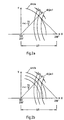
- Fig. 2a substantially corresponds to Fig. 5 with the only difference that there is not only one but a plurality of hyperbolas shown.
- each hyperbola represents the locations of all points having a receiving delay difference of ⁇ tk between the first and the second receiver 200' and 200''.
- the delay time interval ⁇ tk can be varied or can be kept fixed. By varying the value of ⁇ tk the distance between two successive hyperbolas is varied and in that way the distance between two scanning points in the space can be varied.
- Fig. 2b illustrates another modus of operation which differs from the one illustrated in Fig. 2a in the way that additionally the first receiving time T1 at which reflections of the rate of the transmitted radar signal are expected in the receiving signal is changed.
- a variation of the receiving time T1 lets to a plurality of circles, e.g. shells, having different radii according to the different receiving times T1.
- the Y-Z or the X-Z-plane can be mapped by appropriately arranging the transceiver and the second receiver.
- a second embodiment of the invention is shown in Fig. 3. It differs from the first embodiment in that there is not only one second receiver 200'' provided additionally to the transceiver but several receivers 200 n .
- ⁇ tn represents a delay time interval with respect to Tn-1 the time when the signal is received at receiver n-1.
- a variation of T1 or ⁇ tn enables a scanning of the space with a desired density or resolution.
- n-1 receivers since there is not only one but n-1 receivers except the receiver in the transceiver provided, they can be arranged on the co-ordinate axes of a three dimensional space, in that the whole space can be scanned. Evaluation of the receiving signals is done under consideration of the delay time intervals ⁇ tn which represents the delay time between two signals received at receivers n-1 and n.
- the tolerance of the systems is a lot smaller than in conventional systems.
- the claimed systems avoid large uncertainties in values for ⁇ tk and ⁇ tn arising from the evaluation of the difference between Tk or Tn and Tk-1 or Tn-1, respectively, as done in the prior art, by the directly setting the delay time differences ⁇ tk and ⁇ tn between two successively activated receivers. Since ⁇ tk and ⁇ tn can be determined more precisely a similar close tolerance in the position determination is achieved.
Landscapes
- Engineering & Computer Science (AREA)
- Radar, Positioning & Navigation (AREA)
- Remote Sensing (AREA)
- Computer Networks & Wireless Communication (AREA)
- Physics & Mathematics (AREA)
- General Physics & Mathematics (AREA)
- Radar Systems Or Details Thereof (AREA)
Claims (10)
- Verfahren zum Scannen eines Raums, insbesondere des Inneren eines Fahrzeugs, zum Erkennen eines Objekts darin, umfassend die Schritte des
Sendens eines Radarsignals in den Raum,
Empfangens eines Signals an einer ersten Position zu einer ersten Empfangszeit T1 nach der Sendung und an einer zweiten Position zu einer zweiten Empfangszeit T2 = T1 + δt2, wobei T2 für den Verzögerungszeitintervall δt2 bezüglich T1 verzögert ist und wobei der Abstand ΔR zwischen der ersten und zweiten Position die Bedingung erfüllt, daß ΔR > c x δt ist, wobei c die Lichtgeschwindigkeit repräsentiert,
Auswertens von Reflexionen, die in dem empfangenen Signal auf das Radarsignal zurückverfolgt sind, unter Berücksichtigung der verschiedenen Positionen und Empfangszeiten zum Erkennen des Objekts und zum Bestimmen seiner Lage in dem Raum,
Aktivierens des Empfangs des Signals an der zweiten Position nach T2 für eine vorbestimmte Anzahl von k - 2 mal Tk = Tk - 1 + δtk mit k ≥ 3, wobei δtk einen Verzögerungszeitintervall bezüglich Tk - 1 repräsentiert. - Verfahren nach Anspruch 1, dadurch gekennzeichnet, daß T1 variiert wird oder unverändert bleibt, nachdem die vorbestimmte Anzahl von k - 2 Signalen an der zweiten Position empfangen wurde und bevor das Verfahren wiederholt wird.
- Verfahren zum Scannen eines Raums, insbesondere des Inneren eines Fahrzeugs, zum Erkennen eines Objekts darin, umfassend die Schritte des
Sendens eines Radarsignals in den Raum,
Empfangens eines Signals an einer ersten Position zu einer ersten Empfangszeit T1 nach der Sendung und an einer zweiten Position zu einer zweiten Empfangszeit T2 = T1 + δt2, wobei T2 für den Verzögerungszeitintervall δt2 bezüglich T1 verzögert ist und wobei der Abstand ΔR zwischen der ersten und zweiten Position die Bedingung erfüllt, daß ΔR > c x δt ist, wobei c die Lichtgeschwindigkeit repräsentiert,
Auswertens von Reflexionen, die in dem empfangenen Signal auf das Radarsignal zurückverfolgt sind, unter Berücksichtigung der verschiedenen Positionen und Empfangszeiten zum Erkennen des Objekts und zum Bestimmen seiner Lage in dem Raum,
Aktivierens des Empfangs des Signals bei n - 2, wobei n = 3 ist, weiteren Positionen 3...n jeweils zu Zeiten Tn = Tn - 1 + δtn, wobei δtk einen Verzögerungszeitintervall bezüglich Tn - 1 repräsentiert. - Verfahren nach Anspruch 3, dadurch gekennzeichnet, daß δtn - 1 = δtn für alle n ≥ 3 ist.
- Verfahren nach Anspruch 4, dadurch gekennzeichnet, daß δtn für alle n ≥ 3 jeweils variabel ist.
- Radarsystem, das eines der Verfahren nach Anspruch 1 bis 5 ausführt, umfassend:einen Sender, der das Radarsystem in den Raum sendet,n Empfänger, die das Signal an den n verschiedenen Positionen der Empfänger zu verschiedenen Zeiten gemäß den Verfahren empfangen, undeine Auswertungseinheit, die Reflexionen, die auf das Radarsignal zurückverfolgt sind, unter Berücksichtigung der verschiedenen Positionen und Empfangszeiten zum Erkennen eines Objekts und zum Bestimmen seiner Lage in dem Raum auswertet.
- Radarsystem nach Anspruch 6, dadurch gekennzeichnet, daß der Sender und der erste (n = 1) Empfänger zusammengelegt sind und einen Transceiver ausbilden.
- Radarsystem nach einem der Ansprüche 6 oder 7, dadurch gekennzeichnet, daß der Sender ein Schaltgerät umfaßt, das Impulse, die von einem Impulsgeber des Senders vorgesehen sind, vor der Sendung über eine Antenne in Impulse mit jeweils einer geringeren Breite umwandelt.
- Radarsystem nach einem der Ansprüche 6 bis 8, dadurch gekennzeichnet, daß jeder der n Empfänger eine variable Verzögerungseinheit umfaßt, die den Empfang des Empfangssignals bezüglich der Sendezeit des Radarsignals durch den Sender oder bezüglich der Empfangszeit des Empfangssignals an einem vorher aktivierten Empfänger ansteuert.
- Radarsystem nach einem der Ansprüche 6 bis 9, dadurch gekennzeichnet, daß die Empfänger jeweils auf rechtwinkligen Koordinatenachsen eines Koordinatensystems in dem Raum angeordnet sind.
Applications Claiming Priority (2)
| Application Number | Priority Date | Filing Date | Title |
|---|---|---|---|
| DE19903081 | 1999-01-27 | ||
| DE19903081 | 1999-01-27 |
Publications (3)
| Publication Number | Publication Date |
|---|---|
| EP1026520A2 EP1026520A2 (de) | 2000-08-09 |
| EP1026520A3 EP1026520A3 (de) | 2003-01-02 |
| EP1026520B1 true EP1026520B1 (de) | 2004-09-29 |
Family
ID=7895472
Family Applications (1)
| Application Number | Title | Priority Date | Filing Date |
|---|---|---|---|
| EP00101724A Expired - Lifetime EP1026520B1 (de) | 1999-01-27 | 2000-01-27 | Verfahren und Radarsystem zur Detektion eines Objektes mittels Abtastung eines Raums |
Country Status (2)
| Country | Link |
|---|---|
| EP (1) | EP1026520B1 (de) |
| DE (1) | DE60014202T2 (de) |
Families Citing this family (2)
| Publication number | Priority date | Publication date | Assignee | Title |
|---|---|---|---|---|
| RU2332683C2 (ru) * | 2006-10-03 | 2008-08-27 | Владимир Иванович Винокуров | Способ обнаружения радиолокационных сигналов и устройство для его осуществления |
| RU2337377C1 (ru) * | 2007-06-13 | 2008-10-27 | Александр Абрамович Часовской | Радиолокатор |
Family Cites Families (5)
| Publication number | Priority date | Publication date | Assignee | Title |
|---|---|---|---|---|
| GB1234764A (en) * | 1967-08-25 | 1971-06-09 | Nat Res Dev | Solid state radar |
| US5148175A (en) * | 1991-07-05 | 1992-09-15 | Sperry Marine Inc. | High resolution variable range gate generator with programmable timing |
| US5510800A (en) * | 1993-04-12 | 1996-04-23 | The Regents Of The University Of California | Time-of-flight radio location system |
| US5543799A (en) * | 1994-09-02 | 1996-08-06 | Zircon Corporation | Swept range gate radar system for detection of nearby objects |
| GB9520487D0 (en) * | 1995-10-06 | 1995-12-06 | Cambridge Consultants | Short range electromagnetic sensor |
-
2000
- 2000-01-27 EP EP00101724A patent/EP1026520B1/de not_active Expired - Lifetime
- 2000-01-27 DE DE60014202T patent/DE60014202T2/de not_active Expired - Lifetime
Also Published As
| Publication number | Publication date |
|---|---|
| DE60014202T2 (de) | 2005-02-17 |
| EP1026520A3 (de) | 2003-01-02 |
| EP1026520A2 (de) | 2000-08-09 |
| DE60014202D1 (de) | 2004-11-04 |
Similar Documents
| Publication | Publication Date | Title |
|---|---|---|
| US6611759B2 (en) | Method and device for detecting and evaluating objects in the vicinity of a motor vehicle | |
| EP0446678B1 (de) | Polystatisches Korrelationsradar | |
| JP2545958B2 (ja) | ディジタルビームフォーミングレーダ | |
| US5148175A (en) | High resolution variable range gate generator with programmable timing | |
| US6509864B1 (en) | Distance measuring device and method for calibrating a distance measuring device | |
| DE69430195D1 (de) | Ultrabreitbandbewegungssensor für radar | |
| JP2002538445A (ja) | 超音波乗物乗員位置検知システム | |
| EP0184424A2 (de) | Radargerät mit zusammengesetzten Impulsen und Mittel zur Unterdrückung der Interferenz zwischen den Impulsen | |
| US4375641A (en) | Method in a tracking radar to attain a large unambiguous range for detected targets by means of radar pulses with high repetition frequency | |
| KR101300085B1 (ko) | 신호-대-잡음비 증강을 위한 펄스 도플러 위상정합 방법 및시스템 | |
| SE0103356D0 (sv) | Sensoranordnung mit einem Puls-Echo-Radar | |
| EP1475646A2 (de) | Radarvorrichtung | |
| EP1026520B1 (de) | Verfahren und Radarsystem zur Detektion eines Objektes mittels Abtastung eines Raums | |
| US4203112A (en) | Method and system for increasing the distance which can be unambiguously measured by a radar system | |
| WO2000079299A1 (en) | Radar apparatus | |
| JP5506214B2 (ja) | 地中レーダ装置 | |
| NL8006069A (nl) | Werkwijze voor het op afstand bepalen van de toestand van de zee, en inrichting voor het toepassen van de werkwijze. | |
| RU96114930A (ru) | Способ калибровки радиолокатора и радиолокатор | |
| US5062088A (en) | Acoustic measuring system | |
| JPH0886859A (ja) | レーダ装置 | |
| JP2990237B2 (ja) | 目標信号自動検出方法および装置 | |
| JP3182448B2 (ja) | 可変周期相関型探知装置ならびに可変周期相関型信号検出装置 | |
| Lan et al. | Solution to range and velocity ambiguities based on frequency diversity MIMO radar | |
| RU2313110C1 (ru) | Волновой обнаружитель неоднородностей | |
| EP0980009B1 (de) | Radar |
Legal Events
| Date | Code | Title | Description |
|---|---|---|---|
| PUAI | Public reference made under article 153(3) epc to a published international application that has entered the european phase |
Free format text: ORIGINAL CODE: 0009012 |
|
| AK | Designated contracting states |
Kind code of ref document: A2 Designated state(s): AT BE CH CY DE DK ES FI FR GB GR IE IT LI LU MC NL PT SE |
|
| AX | Request for extension of the european patent |
Free format text: AL;LT;LV;MK;RO;SI |
|
| PUAL | Search report despatched |
Free format text: ORIGINAL CODE: 0009013 |
|
| AK | Designated contracting states |
Kind code of ref document: A3 Designated state(s): AT BE CH CY DE DK ES FI FR GB GR IE IT LI LU MC NL PT SE |
|
| AX | Request for extension of the european patent |
Free format text: AL;LT;LV;MK;RO;SI |
|
| RIC1 | Information provided on ipc code assigned before grant |
Free format text: 7G 01S 13/88 A, 7G 01S 13/87 B |
|
| 17P | Request for examination filed |
Effective date: 20030129 |
|
| 17Q | First examination report despatched |
Effective date: 20030401 |
|
| AKX | Designation fees paid |
Designated state(s): DE FR GB IT SE |
|
| GRAP | Despatch of communication of intention to grant a patent |
Free format text: ORIGINAL CODE: EPIDOSNIGR1 |
|
| RTI1 | Title (correction) |
Free format text: METHOD AND RADAR SYSTEM FOR SCANNING A SPACE IN ORDER TO DETECT AN OBJECT THEREIN |
|
| GRAS | Grant fee paid |
Free format text: ORIGINAL CODE: EPIDOSNIGR3 |
|
| GRAA | (expected) grant |
Free format text: ORIGINAL CODE: 0009210 |
|
| AK | Designated contracting states |
Kind code of ref document: B1 Designated state(s): DE FR GB IT SE |
|
| REG | Reference to a national code |
Ref country code: GB Ref legal event code: FG4D |
|
| REG | Reference to a national code |
Ref country code: IE Ref legal event code: FG4D |
|
| REF | Corresponds to: |
Ref document number: 60014202 Country of ref document: DE Date of ref document: 20041104 Kind code of ref document: P |
|
| REG | Reference to a national code |
Ref country code: SE Ref legal event code: TRGR |
|
| PGFP | Annual fee paid to national office [announced via postgrant information from national office to epo] |
Ref country code: GB Payment date: 20050128 Year of fee payment: 6 |
|
| ET | Fr: translation filed | ||
| PLBE | No opposition filed within time limit |
Free format text: ORIGINAL CODE: 0009261 |
|
| STAA | Information on the status of an ep patent application or granted ep patent |
Free format text: STATUS: NO OPPOSITION FILED WITHIN TIME LIMIT |
|
| 26N | No opposition filed |
Effective date: 20050630 |
|
| PG25 | Lapsed in a contracting state [announced via postgrant information from national office to epo] |
Ref country code: GB Free format text: LAPSE BECAUSE OF NON-PAYMENT OF DUE FEES Effective date: 20060127 |
|
| GBPC | Gb: european patent ceased through non-payment of renewal fee |
Effective date: 20060127 |
|
| REG | Reference to a national code |
Ref country code: FR Ref legal event code: TP Owner name: DELPHI INTERNATIONAL OPERATIONS LUXEMBOURG S.A, LU Effective date: 20131218 |
|
| REG | Reference to a national code |
Ref country code: DE Ref legal event code: R082 Ref document number: 60014202 Country of ref document: DE Representative=s name: MANITZ, FINSTERWALD & PARTNER GBR, DE |
|
| REG | Reference to a national code |
Ref country code: DE Ref legal event code: R082 Ref document number: 60014202 Country of ref document: DE Representative=s name: MANITZ, FINSTERWALD & PARTNER GBR, DE Effective date: 20140409 Ref country code: DE Ref legal event code: R081 Ref document number: 60014202 Country of ref document: DE Owner name: DELPHI INTERNATIONAL OPERATIONS LUXEMBOURG S.A, LU Free format text: FORMER OWNER: DELPHI TECHNOLOGIES, INC., TROY, US Effective date: 20140409 Ref country code: DE Ref legal event code: R081 Ref document number: 60014202 Country of ref document: DE Owner name: DELPHI INTERNATIONAL OPERATIONS LUXEMBOURG S.A, LU Free format text: FORMER OWNER: DELPHI TECHNOLOGIES, INC., TROY, MICH., US Effective date: 20140409 Ref country code: DE Ref legal event code: R082 Ref document number: 60014202 Country of ref document: DE Representative=s name: MANITZ FINSTERWALD PATENTANWAELTE PARTMBB, DE Effective date: 20140409 |
|
| REG | Reference to a national code |
Ref country code: FR Ref legal event code: PLFP Year of fee payment: 17 |
|
| REG | Reference to a national code |
Ref country code: FR Ref legal event code: PLFP Year of fee payment: 18 |
|
| REG | Reference to a national code |
Ref country code: FR Ref legal event code: PLFP Year of fee payment: 19 |
|
| REG | Reference to a national code |
Ref country code: DE Ref legal event code: R082 Ref document number: 60014202 Country of ref document: DE Representative=s name: MANITZ FINSTERWALD PATENT- UND RECHTSANWALTSPA, DE Ref country code: DE Ref legal event code: R081 Ref document number: 60014202 Country of ref document: DE Owner name: APTIV TECHNOLOGIES LIMITED, BB Free format text: FORMER OWNER: DELPHI INTERNATIONAL OPERATIONS LUXEMBOURG S.A R.L., 4940 HAUTCHARAGE, LU Ref country code: DE Ref legal event code: R082 Ref document number: 60014202 Country of ref document: DE Representative=s name: MANITZ FINSTERWALD PATENTANWAELTE PARTMBB, DE Ref country code: DE Ref legal event code: R081 Ref document number: 60014202 Country of ref document: DE Owner name: APTIV TECHNOLOGIES LIMITED, BB Free format text: FORMER OWNER: DELPHI INTERNATIONAL OPERATIONS LUXEMBOURG S.A R.L., 4940 BASCHARAGE, LU |
|
| PGFP | Annual fee paid to national office [announced via postgrant information from national office to epo] |
Ref country code: FR Payment date: 20190125 Year of fee payment: 20 Ref country code: IT Payment date: 20190123 Year of fee payment: 20 Ref country code: DE Payment date: 20190129 Year of fee payment: 20 |
|
| PGFP | Annual fee paid to national office [announced via postgrant information from national office to epo] |
Ref country code: SE Payment date: 20190129 Year of fee payment: 20 |
|
| REG | Reference to a national code |
Ref country code: DE Ref legal event code: R071 Ref document number: 60014202 Country of ref document: DE |
|
| REG | Reference to a national code |
Ref country code: SE Ref legal event code: EUG |