EP1026534A1 - Système de télescope orientable - Google Patents
Système de télescope orientable Download PDFInfo
- Publication number
- EP1026534A1 EP1026534A1 EP00101743A EP00101743A EP1026534A1 EP 1026534 A1 EP1026534 A1 EP 1026534A1 EP 00101743 A EP00101743 A EP 00101743A EP 00101743 A EP00101743 A EP 00101743A EP 1026534 A1 EP1026534 A1 EP 1026534A1
- Authority
- EP
- European Patent Office
- Prior art keywords
- mirror
- telescope arrangement
- arrangement
- telescope
- curved mirror
- Prior art date
- Legal status (The legal status is an assumption and is not a legal conclusion. Google has not performed a legal analysis and makes no representation as to the accuracy of the status listed.)
- Granted
Links
- 230000005540 biological transmission Effects 0.000 claims description 19
- 238000003384 imaging method Methods 0.000 claims description 16
- 230000005855 radiation Effects 0.000 abstract 1
- 210000003128 head Anatomy 0.000 description 15
- 230000003287 optical effect Effects 0.000 description 3
- 230000006978 adaptation Effects 0.000 description 1
- 230000004075 alteration Effects 0.000 description 1
- 230000001419 dependent effect Effects 0.000 description 1
- 238000005553 drilling Methods 0.000 description 1
- 230000002349 favourable effect Effects 0.000 description 1
- 230000003760 hair shine Effects 0.000 description 1
- 238000003702 image correction Methods 0.000 description 1
- 238000009434 installation Methods 0.000 description 1
- 230000005012 migration Effects 0.000 description 1
- 238000013508 migration Methods 0.000 description 1
- 230000008092 positive effect Effects 0.000 description 1
- 210000001747 pupil Anatomy 0.000 description 1
- 230000035945 sensitivity Effects 0.000 description 1
- 230000006641 stabilisation Effects 0.000 description 1
- 238000011105 stabilization Methods 0.000 description 1
Images



Classifications
-
- G—PHYSICS
- G02—OPTICS
- G02B—OPTICAL ELEMENTS, SYSTEMS OR APPARATUS
- G02B17/00—Systems with reflecting surfaces, with or without refracting elements
- G02B17/02—Catoptric systems, e.g. image erecting and reversing system
- G02B17/06—Catoptric systems, e.g. image erecting and reversing system using mirrors only, i.e. having only one curved mirror
- G02B17/0626—Catoptric systems, e.g. image erecting and reversing system using mirrors only, i.e. having only one curved mirror using three curved mirrors
- G02B17/0642—Catoptric systems, e.g. image erecting and reversing system using mirrors only, i.e. having only one curved mirror using three curved mirrors off-axis or unobscured systems in which not all of the mirrors share a common axis of rotational symmetry, e.g. at least one of the mirrors is warped, tilted or decentered with respect to the other elements
-
- G—PHYSICS
- G02—OPTICS
- G02B—OPTICAL ELEMENTS, SYSTEMS OR APPARATUS
- G02B17/00—Systems with reflecting surfaces, with or without refracting elements
- G02B17/02—Catoptric systems, e.g. image erecting and reversing system
- G02B17/06—Catoptric systems, e.g. image erecting and reversing system using mirrors only, i.e. having only one curved mirror
- G02B17/0605—Catoptric systems, e.g. image erecting and reversing system using mirrors only, i.e. having only one curved mirror using two curved mirrors
- G02B17/0621—Catoptric systems, e.g. image erecting and reversing system using mirrors only, i.e. having only one curved mirror using two curved mirrors off-axis or unobscured systems in which not all of the mirrors share a common axis of rotational symmetry, e.g. at least one of the mirrors is warped, tilted or decentered with respect to the other elements
Definitions
- the invention relates to a directional telescopic arrangement according to the preamble of Claim 1.
- Such a directional telescope arrangement is particularly suitable for a stabilized one Aerial camera or reconnaissance camera suitable.
- a generic telescope arrangement is known from EP 0 385 079 A2.
- This for the A telescopic arrangement provided in a tracked vehicle is a mirror telescope after Cassegrain with a Nasmyth arrangement, in which a central drilling of the Main mirror is avoided by arching in front of the main mirror or the first A plane mirror deflects the beam path by 90 °.
- the object of the invention is an improved straightenable telescope arrangement with high Provide light intensity and a large field of view.
- the first curved mirror and the second curved mirrors arranged obliquely relative to the viewing direction of the telescope arrangement and the second curved mirror lies outside the one on the entrance side up to the first curved one Beam path running in a mirror.
- This can be done especially with fast Cassegrain telescope arrangements considerable shadowing from the second curved mirror and possibly the plan deflecting mirror, which shows both the light intensity and the image quality minimized, avoided.
- the plane deflecting mirror can be made in this way be arranged so that it is no longer surrounded by the imaging beam, whereby in the case of a motor-driven deflecting mirror, the design requirements for the Drive are significantly reduced, which is due to the sensitivity and accuracy of the drive and thereby also has a very positive effect on the image quality.
- the directional range of the telescope arrangement be particularly large.
- Outlook head can e.g. a directional range of plus / minus 140 ° in relation to a longitudinal axis the telescope arrangement, which correspond to the direction of flight in the case of an aerial camera would be achieved.
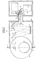
- FIG. 1 shows a telescopic arrangement 1 according to the invention in a front view seen axial longitudinal section and Figure 2 shows the telescope assembly 1 in one sectional side view according to the arrows II of Figure 1.
- the telescopic arrangement 1 comprises a first curved mirror 3, which one along it a line of sight 5 incident light bundle 7 collects and on a second curved Mirror 9 steers.
- the second curved mirror 9 directs the parallel light beam 7 over one Intermediate focus or an intermediate image 11 on a flat deflecting mirror 13, which the Beams of light 7 orthogonal to the plane of the drawing in FIG. 1 into one recognizable in FIG Transmission system 15 forwards.
- the transmission system 15 comprises a large aspherical curved mirror 17 and Plane mirror 19, 21, 23 and 25.
- the intermediate image 11 is created by the transmission system 15 transmitted to a further focus or intermediate image 27, with the plane mirrors 19, 21, 23 and 25 an adaptation to externally predeterminable installation conditions can be achieved can.
- the light beam 7 is emitted by a dichroic beam splitter 29 split into an infrared portion 31 and a visible portion 33.
- the infrared portion 31 is from a refractive optic 35 via a pivotable mirror 37 to a Infrared camera unit 39 steered.
- the visible part 33 of the beam is over a refractive optics 41 and a pivotable deflecting mirror 43 to a visible light capturing camera unit 45 steered.
- the pivotable deflecting mirror 37 and 43 can serve both for scanning the image field and for image migration compensation if the telescopic arrangement 1 on a moving telescopic support, e.g. one Reconnaissance aircraft is used.
- the first curved mirror 3 and the second curved mirror 9 are relative to the line of sight 5 or to a continuation 47 of the line of sight between mirror 3 and mirror 9 obliquely arranged, the second curved mirror 9 outside of the curved up to the first Mirror 3 extending beam path or beam 7 is arranged.
- This oblique and asymmetrical arrangement of mirrors 3 and 9 is therefore a shade-free Schiefspiegler system implemented.
- the curved mirrors 3 and 9 are received in a view head 49 and together with the viewing head 49 pivotable about a directional axis 51.
- the transmission system 15 together with the downstream detector optics is also very schematic in one Detector housing 53 shown arranged, which is substantially transverse to Directional axis 51 extends.
- the plane deflection mirror arranged in the region of the directional axis 51 13 follows a pivotal movement of the viewing head 49 about the directional axis 51 with half Angular velocity, d. H. when the view head 49 is pivoted by one Angle ⁇ , the plane deflecting mirror 13 must also be pivoted about the directional axis 51, however, this only by an angle ⁇ / 2.
- the directional telescopic arrangement 1 shown schematically in Figures 1 and 2 includes an asymmetrical arrangement of two imaging systems connected in series with focus 11 in between, the first being formed from mirrors 3 and 9 System has a high light intensity and the second system, the transmission system 15 with the curved mirror 17 comprises.
- the telescopic arrangement 1 all three domed mirrors 3, 9 and 17 in particular by their three fully aspherically correctable Areas for image correction are used.
- the telescopic arrangement 1 a high light intensity and a large field of view within the corrected area, whereby the optical structure of the telescope arrangement 1, in particular for focal lengths from approx. one meter upwards and apertures above approx. 320 mm.
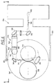
- FIG. 3 shows another view according to the invention in a view corresponding to FIG. 1 directional telescope assembly 101.
- the telescope assembly 1 corresponding elements of Telescope arrangement 101 have the same reference numbers, increased by the number 100. For the description of which is referred to the description of the telescopic arrangement 1.
- the telescopic arrangement 101 comprises between the second curved mirror 109 and the detector housing-side transmission system in addition a flat deflecting mirror 112 a further flat deflecting mirror 114.
- the two Deflecting mirrors 112 and 114 are arranged in the region of the directional axis 151 and are at a pivoting of the outlook head 149 about the directional axis 151 does not also pivot.
- the telescope arrangement 101 thus has a periscope-like structure.
- the result Conditional design simplification compared to the telescope arrangement 1 must, however through a in the area of the transmission system and the camera instrumentation of the Telescope assembly 101 image rotation to be eliminated.
- the third curved mirror of the telescope arrangement 101 is analogous to the telescope arrangement 1 arranged in the transmission system side of the detector housing and therefore not in FIG. 3 detect.
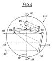
- FIG. 4 shows a further telescope arrangement 201 according to the invention
- Telescope arrangement 1 corresponding elements of the telescope arrangement 201 carry the same reference numbers increased by the number 200.
- the telescope assembly 201 comprises a fourth domed mirror 218, which plan the beam of rays 207 from the second curved mirror 209 to the Deflecting mirror 213 deflects.
- the plane deflecting mirror 213 follows the deflecting mirror analogously 13 of the telescopic arrangement 1 a pivoting movement of the viewing head 249 around the Straightening axis 251 with half the angular velocity.
- FIGS A fourth telescope arrangement according to the invention is shown schematically in FIGS shown.
- Lookout head 349 is in a sectional plan view in FIG. 5 and in a view in FIG Recognize side view.
- the terms top view and side view refer to one of the preferred application forms of the telescope arrangement according to the invention for Lateral view from an aircraft, with directional axis 351 essentially orthogonal to the flight direction and a longitudinal axis 302 of a detector housing 353 in to be arranged essentially parallel to the direction of flight.
- the telescope arrangement 301 comprises a first curved one designed as a concave mirror Mirror 303, which shines a light beam 307 incident along a line of sight 305 onto a Convex mirror formed second domed mirror 309 concentrated.
- the imaging beam path is the second curved mirror 309 as a concave mirror trained third curved mirror 310 downstream.
- the imaging beam path continues from the concave mirror 310 to a planar one Deflecting mirror 312 and from this to a further plan deflecting mirror 314.
- the imaging beam path from the plane deflection mirror 314 is further deflected to a third planar deflecting mirror 316.
- a focus or Intermediate image 311 is created and that the plane mirror 314 and 316 in the area of the directional axis 351 are arranged, the plane mirrors 314 and 312 and the curved mirrors 303, 309 and 310 together with the viewing head 349 can be pivoted about the directional axis 351 are, while the plane mirror 316 does not follow a pivoting movement of the viewing head, but relative to the detector housing 353 always assumes the same orientation and position.
- FIG. 5 The section line indicated by arrows VII in FIG. 5 is relative to the longitudinal axis of the detector housing 302 rotated by an angle of 30 °.
- Figures 6 and 7 can be the Take the orientations of the flat deflecting mirrors 312, 314 and 316.
- FIGS. 5 to 7 also show that which is arranged in the detector housing 353 or relative to it Detector housing 353 stationary transmission system 315 of the telescope arrangement 301 detect.
- the imaging beam of a dichroic beam splitter 329 into an infrared portion 331 and a visible portion 333 split.
- the infrared portion 331 is via refractive optics 335, one as a Dove prism or Taylor prism trained image erection unit 336, further plane Deflecting mirror 338 to form an intermediate focus or intermediate image 328 to one a pivotable deflecting mirror and a detector unit comprising an infrared camera 339 managed.
- the detector unit 339 essentially corresponds to that in FIG Connection with the detector unit described in FIG. 2.
- the visible beam 331 is only schematic over one shown refractive optics 341, a deflection element 342, an image erection unit 346 and plane deflection mirrors 360 and 362 led to a detector unit 345. Also in Beam path of the visible light beam 331 is between the deflecting mirror 362 and an intermediate focus or an intermediate image 329, which like the Intermediate image 328 also lies in the area of the longitudinal axis 302 of the detector housing 353.
- the beam splitting takes place in an area of the Imaging beam path with divergent light beam.
- the area of Imaging beam path with a parallel light beam after the beam splitter 329 is in each case used for image erection.
- the transmission system 315 enables the transmission of the Intermediate image 311 to intermediate images 328 and 329 with intersecting optical channels, an area 354 narrowing due to the mounting of the telescope arrangement of the detector housing 353 need not be expanded.
- the optical structure of the telescope arrangement 301 is particularly suitable for focal lengths below approximately one meter and fields of view in the range of 2 ° to 5 ° or even above out.
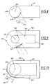
- FIG. 8 shows a telescope arrangement 401 according to the invention with a lookout head 449, which is relative to a directional axis 451 which is orthogonal to the drawing plane of FIG Detector housing 453 is rotatable, shown very schematically.
- the lookout head 449 points a spherical viewing window 450 which can be pivoted together with this, through which a light bundle 407 enters along the viewing direction 405.
- FIG. 9 shows a telescopic arrangement 501 accommodated in a telescopic container 502 shown schematically, wearing the corresponding to the elements of Figure 8 Elements of FIG. 9 have the same reference numerals as in FIG. 8, increased by the number 100.
- the telescopic container 502 is separate about a directional axis 551 has pivotable container hood 570 with a viewing window 571.
- This decoupled arrangement of view head 549 and tracked window 571 is in the With regard to the use of the telescopic arrangement 501 as an aircraft-based one Reconnaissance camera particularly favorable for stabilization.
- the Telescopic container 502 arranged as a so-called pod on the fuselage of the carrier aircraft.
- FIG. 10 shows a telescopic arrangement 601 in a telescopic container 602, which is fixed Has lookout window 671.
- the elements of FIG. 8 corresponding to the elements of FIG 10 has the same reference numerals as in FIG. 8, increased by the number 200.
Landscapes
- Physics & Mathematics (AREA)
- General Physics & Mathematics (AREA)
- Optics & Photonics (AREA)
- Telescopes (AREA)
Applications Claiming Priority (2)
| Application Number | Priority Date | Filing Date | Title |
|---|---|---|---|
| DE19904687 | 1999-02-05 | ||
| DE19904687A DE19904687A1 (de) | 1999-02-05 | 1999-02-05 | Richtbare Teleskopanordnung |
Publications (2)
| Publication Number | Publication Date |
|---|---|
| EP1026534A1 true EP1026534A1 (fr) | 2000-08-09 |
| EP1026534B1 EP1026534B1 (fr) | 2004-06-02 |
Family
ID=7896535
Family Applications (1)
| Application Number | Title | Priority Date | Filing Date |
|---|---|---|---|
| EP00101743A Expired - Lifetime EP1026534B1 (fr) | 1999-02-05 | 2000-01-28 | Système de télescope orientable |
Country Status (3)
| Country | Link |
|---|---|
| US (1) | US6441957B1 (fr) |
| EP (1) | EP1026534B1 (fr) |
| DE (2) | DE19904687A1 (fr) |
Cited By (4)
| Publication number | Priority date | Publication date | Assignee | Title |
|---|---|---|---|---|
| EP1907898A4 (fr) * | 2005-07-01 | 2010-11-24 | Flir Systems | Systeme de stabilisation d'image |
| US9298014B2 (en) | 2005-07-01 | 2016-03-29 | Flir Systems, Inc. | Image stabilization system |
| CN110727092A (zh) * | 2019-10-08 | 2020-01-24 | 中国科学院光电技术研究所 | 一种基于自由曲面的离轴反射式两镜扩束系统 |
| WO2021150336A1 (fr) * | 2020-01-22 | 2021-07-29 | Raytheon Company | Capteur multicanal utilisant un triplet réfléchissant arrêté par l'arrière |
Families Citing this family (9)
| Publication number | Priority date | Publication date | Assignee | Title |
|---|---|---|---|---|
| DE10229816A1 (de) * | 2002-06-28 | 2004-01-15 | Carl Zeiss Smt Ag | Vorrichtung zur Erzeugung einer konvergenten Lichtwellenfront und System zur interferometrischen Linsenflächenvermessung |
| US6970286B1 (en) | 2004-06-23 | 2005-11-29 | Corning Incorporated | Multiple field of view reflective telescope |
| IL166267A0 (en) | 2005-01-13 | 2006-01-15 | Oleg Lliich Epshtein | Three mirror anastigmatic telescope |
| US7741557B2 (en) * | 2005-12-19 | 2010-06-22 | Corning Incorporated | Apparatus for obtaining radiant energy |
| DE102006025210A1 (de) * | 2006-05-29 | 2007-12-06 | Burkhard Koch | Abschattungsfreies Spiegelteleskop |
| US8154712B2 (en) * | 2008-07-23 | 2012-04-10 | Corning Incorporated | Insertion of laser path in multiple field of view reflective telescope |
| US8947778B2 (en) * | 2010-06-01 | 2015-02-03 | Richard F. Horton | Two mirror unobscured telescopes with tilted focal surfaces |
| DE102012017049A1 (de) | 2012-08-29 | 2014-03-06 | Khs Gmbh | Vorrichtung zum Inspizieren von Gegenständen |
| US10761307B2 (en) * | 2016-12-06 | 2020-09-01 | Raytheon Company | Bypass optical switch and methods |
Citations (5)
| Publication number | Priority date | Publication date | Assignee | Title |
|---|---|---|---|---|
| EP0385079A2 (fr) * | 1989-03-03 | 1990-09-05 | STN ATLAS Elektronik GmbH | Système de visualisation pour véhicules en chaîne |
| US5309276A (en) * | 1991-08-29 | 1994-05-03 | Optical Research Associates | Catoptric optical system including concave and convex reflectors |
| EP0601871A1 (fr) * | 1992-12-11 | 1994-06-15 | Hughes Aircraft Company | Système réflectif grand-angulaire lumineux sans obturation avec marche des rayons pliée |
| US5379157A (en) * | 1993-12-02 | 1995-01-03 | Hughes Aircraft Company | Compact, folded wide-angle large reflective unobscured optical system |
| EP0863421A1 (fr) * | 1997-02-26 | 1998-09-09 | HE HOLDINGS, INC. dba HUGHES ELECTRONICS | Un système optique réflectif |
Family Cites Families (3)
| Publication number | Priority date | Publication date | Assignee | Title |
|---|---|---|---|---|
| US4993818A (en) * | 1988-10-17 | 1991-02-19 | Hughes Aircraft Company | Continuous zoom all-reflective optical system |
| FR2711251B1 (fr) * | 1993-10-15 | 1996-01-26 | Matra Marconi Space France | Télescope pour imagerie infrarouge ou visible. |
| US6020994A (en) * | 1998-09-23 | 2000-02-01 | Raytheon Company | Integrated multifunctional multispectral sight assembly and method |
-
1999
- 1999-02-05 DE DE19904687A patent/DE19904687A1/de not_active Withdrawn
-
2000
- 2000-01-28 DE DE50006635T patent/DE50006635D1/de not_active Expired - Fee Related
- 2000-01-28 EP EP00101743A patent/EP1026534B1/fr not_active Expired - Lifetime
- 2000-02-03 US US09/497,256 patent/US6441957B1/en not_active Expired - Fee Related
Patent Citations (5)
| Publication number | Priority date | Publication date | Assignee | Title |
|---|---|---|---|---|
| EP0385079A2 (fr) * | 1989-03-03 | 1990-09-05 | STN ATLAS Elektronik GmbH | Système de visualisation pour véhicules en chaîne |
| US5309276A (en) * | 1991-08-29 | 1994-05-03 | Optical Research Associates | Catoptric optical system including concave and convex reflectors |
| EP0601871A1 (fr) * | 1992-12-11 | 1994-06-15 | Hughes Aircraft Company | Système réflectif grand-angulaire lumineux sans obturation avec marche des rayons pliée |
| US5379157A (en) * | 1993-12-02 | 1995-01-03 | Hughes Aircraft Company | Compact, folded wide-angle large reflective unobscured optical system |
| EP0863421A1 (fr) * | 1997-02-26 | 1998-09-09 | HE HOLDINGS, INC. dba HUGHES ELECTRONICS | Un système optique réflectif |
Cited By (6)
| Publication number | Priority date | Publication date | Assignee | Title |
|---|---|---|---|---|
| EP1907898A4 (fr) * | 2005-07-01 | 2010-11-24 | Flir Systems | Systeme de stabilisation d'image |
| US7862188B2 (en) | 2005-07-01 | 2011-01-04 | Flir Systems, Inc. | Image detection improvement via compensatory high frequency motions of an undedicated mirror |
| US9298014B2 (en) | 2005-07-01 | 2016-03-29 | Flir Systems, Inc. | Image stabilization system |
| CN110727092A (zh) * | 2019-10-08 | 2020-01-24 | 中国科学院光电技术研究所 | 一种基于自由曲面的离轴反射式两镜扩束系统 |
| WO2021150336A1 (fr) * | 2020-01-22 | 2021-07-29 | Raytheon Company | Capteur multicanal utilisant un triplet réfléchissant arrêté par l'arrière |
| US11287637B2 (en) | 2020-01-22 | 2022-03-29 | Raytheon Company | Multi-channel sensor using a rear-stopped reflective triplet |
Also Published As
| Publication number | Publication date |
|---|---|
| DE19904687A1 (de) | 2000-08-10 |
| DE50006635D1 (de) | 2004-07-08 |
| US6441957B1 (en) | 2002-08-27 |
| EP1026534B1 (fr) | 2004-06-02 |
Similar Documents
| Publication | Publication Date | Title |
|---|---|---|
| EP1022600B1 (fr) | Caméra stabilisée | |
| DE3529026C2 (fr) | ||
| EP0538671B1 (fr) | Autodirecteur, en particulier pour le guidage des missiles | |
| DE69626292T2 (de) | System für tag- und nachtsicht | |
| EP2533003B1 (fr) | Dispositif optique destiné au guidage du rayonnement d'une scène sur un détecteur | |
| EP1308748B1 (fr) | Capteur optique avec un trajet optique et un laser transmettant un faisceau parallèle à l'axe optique du trajet optique | |
| EP1026534B1 (fr) | Système de télescope orientable | |
| DE69829459T2 (de) | Optisches system und verfahren zur erzeugung von korrigierten optischen bildern | |
| DE102015217908A1 (de) | Lidarsensor | |
| DE2746076A1 (de) | Rundblickperiskop fuer tagsicht und waermebild | |
| DE3127990C2 (de) | Optisches Beobachtungsgerät | |
| DE3823647A1 (de) | Rundblick-periskop | |
| DE3300728A1 (de) | Ein im infraroten spektralbereich arbeitendes optisches beobachtungssystem | |
| EP2131229A2 (fr) | Dispositif doté d'un système de détermination optique | |
| EP0385079B1 (fr) | Système de visualisation pour véhicules en chaîne | |
| DE10135222B4 (de) | Vorrichtung zum Erfassen einer Objektszene | |
| DE3428990A1 (de) | Vorrichtung zur harmonisierung der optischen achsen eines visiers | |
| DE69111032T2 (de) | Selbst kalibrierendes optronisches System zur infraroten Beobachtung sowie ein richtungsweisender Korb ein solches System enthaltend. | |
| DE3630701A1 (de) | Optisches visiergeraet fuer helikopter | |
| EP1764639B1 (fr) | Télescope à réflecteurs obliques avec trois surfaces miroitées | |
| DE3931883C1 (fr) | ||
| EP0967583B1 (fr) | Dispositif détecteur optoélectronique | |
| EP2466246B1 (fr) | Optique cassegrain | |
| DE102010055492B4 (de) | Cassegrainoptik | |
| DE19720903B4 (de) | Einrichtung zur Achsparallelisierung eines Wärmebildgerätes |
Legal Events
| Date | Code | Title | Description |
|---|---|---|---|
| PUAI | Public reference made under article 153(3) epc to a published international application that has entered the european phase |
Free format text: ORIGINAL CODE: 0009012 |
|
| AK | Designated contracting states |
Kind code of ref document: A1 Designated state(s): DE FR GB |
|
| AX | Request for extension of the european patent |
Free format text: AL;LT;LV;MK;RO;SI |
|
| 17P | Request for examination filed |
Effective date: 20010206 |
|
| AKX | Designation fees paid |
Free format text: DE FR GB |
|
| 17Q | First examination report despatched |
Effective date: 20010329 |
|
| GRAP | Despatch of communication of intention to grant a patent |
Free format text: ORIGINAL CODE: EPIDOSNIGR1 |
|
| GRAS | Grant fee paid |
Free format text: ORIGINAL CODE: EPIDOSNIGR3 |
|
| GRAA | (expected) grant |
Free format text: ORIGINAL CODE: 0009210 |
|
| AK | Designated contracting states |
Kind code of ref document: B1 Designated state(s): DE FR GB |
|
| REG | Reference to a national code |
Ref country code: GB Ref legal event code: FG4D Free format text: NOT ENGLISH |
|
| REF | Corresponds to: |
Ref document number: 50006635 Country of ref document: DE Date of ref document: 20040708 Kind code of ref document: P |
|
| GBT | Gb: translation of ep patent filed (gb section 77(6)(a)/1977) |
Effective date: 20040811 |
|
| ET | Fr: translation filed | ||
| PLBE | No opposition filed within time limit |
Free format text: ORIGINAL CODE: 0009261 |
|
| STAA | Information on the status of an ep patent application or granted ep patent |
Free format text: STATUS: NO OPPOSITION FILED WITHIN TIME LIMIT |
|
| 26N | No opposition filed |
Effective date: 20050303 |
|
| PGFP | Annual fee paid to national office [announced via postgrant information from national office to epo] |
Ref country code: DE Payment date: 20080122 Year of fee payment: 9 Ref country code: GB Payment date: 20080124 Year of fee payment: 9 |
|
| PGFP | Annual fee paid to national office [announced via postgrant information from national office to epo] |
Ref country code: FR Payment date: 20080111 Year of fee payment: 9 |
|
| GBPC | Gb: european patent ceased through non-payment of renewal fee |
Effective date: 20090128 |
|
| PG25 | Lapsed in a contracting state [announced via postgrant information from national office to epo] |
Ref country code: DE Free format text: LAPSE BECAUSE OF NON-PAYMENT OF DUE FEES Effective date: 20090801 |
|
| REG | Reference to a national code |
Ref country code: FR Ref legal event code: ST Effective date: 20091030 |
|
| PG25 | Lapsed in a contracting state [announced via postgrant information from national office to epo] |
Ref country code: GB Free format text: LAPSE BECAUSE OF NON-PAYMENT OF DUE FEES Effective date: 20090128 |
|
| PG25 | Lapsed in a contracting state [announced via postgrant information from national office to epo] |
Ref country code: FR Free format text: LAPSE BECAUSE OF NON-PAYMENT OF DUE FEES Effective date: 20090202 |