EP1026540A1 - Réseau thermiquement accordable à fibre optique comprenant boitier pour performance améliorée - Google Patents
Réseau thermiquement accordable à fibre optique comprenant boitier pour performance améliorée Download PDFInfo
- Publication number
- EP1026540A1 EP1026540A1 EP00300565A EP00300565A EP1026540A1 EP 1026540 A1 EP1026540 A1 EP 1026540A1 EP 00300565 A EP00300565 A EP 00300565A EP 00300565 A EP00300565 A EP 00300565A EP 1026540 A1 EP1026540 A1 EP 1026540A1
- Authority
- EP
- European Patent Office
- Prior art keywords
- grating
- fiber
- packaged
- vessel
- optical fiber
- Prior art date
- Legal status (The legal status is an assumption and is not a legal conclusion. Google has not performed a legal analysis and makes no representation as to the accuracy of the status listed.)
- Withdrawn
Links
- 239000013307 optical fiber Substances 0.000 title claims description 13
- 238000004806 packaging method and process Methods 0.000 title description 5
- 239000000835 fiber Substances 0.000 claims abstract description 55
- 238000010438 heat treatment Methods 0.000 claims description 11
- 239000011248 coating agent Substances 0.000 claims description 6
- 238000000576 coating method Methods 0.000 claims description 6
- 238000001816 cooling Methods 0.000 claims 2
- 238000002955 isolation Methods 0.000 abstract description 4
- 239000003570 air Substances 0.000 description 19
- 230000003287 optical effect Effects 0.000 description 13
- 239000006185 dispersion Substances 0.000 description 5
- 239000000463 material Substances 0.000 description 4
- 230000000737 periodic effect Effects 0.000 description 4
- 239000002019 doping agent Substances 0.000 description 3
- 230000020169 heat generation Effects 0.000 description 3
- 230000002123 temporal effect Effects 0.000 description 3
- VYPSYNLAJGMNEJ-UHFFFAOYSA-N Silicium dioxide Chemical compound O=[Si]=O VYPSYNLAJGMNEJ-UHFFFAOYSA-N 0.000 description 2
- 229920001971 elastomer Polymers 0.000 description 2
- 239000011521 glass Substances 0.000 description 2
- 239000002184 metal Substances 0.000 description 2
- 230000003595 spectral effect Effects 0.000 description 2
- 238000001228 spectrum Methods 0.000 description 2
- 239000004698 Polyethylene Substances 0.000 description 1
- 230000001133 acceleration Effects 0.000 description 1
- 239000004964 aerogel Substances 0.000 description 1
- 239000012080 ambient air Substances 0.000 description 1
- 238000005253 cladding Methods 0.000 description 1
- 230000001419 dependent effect Effects 0.000 description 1
- 230000000694 effects Effects 0.000 description 1
- 229910001651 emery Inorganic materials 0.000 description 1
- 230000002708 enhancing effect Effects 0.000 description 1
- 230000007613 environmental effect Effects 0.000 description 1
- 238000001914 filtration Methods 0.000 description 1
- 239000012530 fluid Substances 0.000 description 1
- 239000006260 foam Substances 0.000 description 1
- 229910052732 germanium Inorganic materials 0.000 description 1
- GNPVGFCGXDBREM-UHFFFAOYSA-N germanium atom Chemical compound [Ge] GNPVGFCGXDBREM-UHFFFAOYSA-N 0.000 description 1
- 230000005484 gravity Effects 0.000 description 1
- BHEPBYXIRTUNPN-UHFFFAOYSA-N hydridophosphorus(.) (triplet) Chemical compound [PH] BHEPBYXIRTUNPN-UHFFFAOYSA-N 0.000 description 1
- 230000002452 interceptive effect Effects 0.000 description 1
- 230000007774 longterm Effects 0.000 description 1
- 239000004033 plastic Substances 0.000 description 1
- 229920003023 plastic Polymers 0.000 description 1
- -1 polyethylene Polymers 0.000 description 1
- 229920000573 polyethylene Polymers 0.000 description 1
- 238000004321 preservation Methods 0.000 description 1
- 230000001902 propagating effect Effects 0.000 description 1
- 230000005855 radiation Effects 0.000 description 1
- 238000002310 reflectometry Methods 0.000 description 1
- 239000004065 semiconductor Substances 0.000 description 1
- 230000035945 sensitivity Effects 0.000 description 1
- 238000007493 shaping process Methods 0.000 description 1
- 239000000377 silicon dioxide Substances 0.000 description 1
- 229920002379 silicone rubber Polymers 0.000 description 1
- 239000004945 silicone rubber Substances 0.000 description 1
- 230000006641 stabilisation Effects 0.000 description 1
- 238000011105 stabilization Methods 0.000 description 1
- 230000003068 static effect Effects 0.000 description 1
- 230000036962 time dependent Effects 0.000 description 1
- 238000009424 underpinning Methods 0.000 description 1
Images

Classifications
-
- H—ELECTRICITY
- H01—ELECTRIC ELEMENTS
- H01S—DEVICES USING THE PROCESS OF LIGHT AMPLIFICATION BY STIMULATED EMISSION OF RADIATION [LASER] TO AMPLIFY OR GENERATE LIGHT; DEVICES USING STIMULATED EMISSION OF ELECTROMAGNETIC RADIATION IN WAVE RANGES OTHER THAN OPTICAL
- H01S3/00—Lasers, i.e. devices using stimulated emission of electromagnetic radiation in the infrared, visible or ultraviolet wave range
- H01S3/05—Construction or shape of optical resonators; Accommodation of active medium therein; Shape of active medium
- H01S3/06—Construction or shape of active medium
- H01S3/063—Waveguide lasers, i.e. whereby the dimensions of the waveguide are of the order of the light wavelength
- H01S3/067—Fibre lasers
- H01S3/06754—Fibre amplifiers
- H01S3/06758—Tandem amplifiers
-
- G—PHYSICS
- G02—OPTICS
- G02B—OPTICAL ELEMENTS, SYSTEMS OR APPARATUS
- G02B6/00—Light guides; Structural details of arrangements comprising light guides and other optical elements, e.g. couplings
- G02B6/02—Optical fibres with cladding with or without a coating
- G02B6/02057—Optical fibres with cladding with or without a coating comprising gratings
- G02B6/02076—Refractive index modulation gratings, e.g. Bragg gratings
- G02B6/02123—Refractive index modulation gratings, e.g. Bragg gratings characterised by the method of manufacture of the grating
-
- G—PHYSICS
- G02—OPTICS
- G02B—OPTICAL ELEMENTS, SYSTEMS OR APPARATUS
- G02B6/00—Light guides; Structural details of arrangements comprising light guides and other optical elements, e.g. couplings
- G02B6/02—Optical fibres with cladding with or without a coating
- G02B6/02057—Optical fibres with cladding with or without a coating comprising gratings
- G02B6/02076—Refractive index modulation gratings, e.g. Bragg gratings
- G02B6/02195—Refractive index modulation gratings, e.g. Bragg gratings characterised by means for tuning the grating
- G02B6/02204—Refractive index modulation gratings, e.g. Bragg gratings characterised by means for tuning the grating using thermal effects, e.g. heating or cooling of a temperature sensitive mounting body
-
- G—PHYSICS
- G02—OPTICS
- G02B—OPTICAL ELEMENTS, SYSTEMS OR APPARATUS
- G02B6/00—Light guides; Structural details of arrangements comprising light guides and other optical elements, e.g. couplings
- G02B6/24—Coupling light guides
- G02B6/26—Optical coupling means
- G02B6/28—Optical coupling means having data bus means, i.e. plural waveguides interconnected and providing an inherently bidirectional system by mixing and splitting signals
- G02B6/293—Optical coupling means having data bus means, i.e. plural waveguides interconnected and providing an inherently bidirectional system by mixing and splitting signals with wavelength selective means
- G02B6/29304—Optical coupling means having data bus means, i.e. plural waveguides interconnected and providing an inherently bidirectional system by mixing and splitting signals with wavelength selective means operating by diffraction, e.g. grating
- G02B6/29316—Light guides comprising a diffractive element, e.g. grating in or on the light guide such that diffracted light is confined in the light guide
- G02B6/29317—Light guides of the optical fibre type
- G02B6/29319—With a cascade of diffractive elements or of diffraction operations
- G02B6/2932—With a cascade of diffractive elements or of diffraction operations comprising a directional router, e.g. directional coupler, circulator
-
- G—PHYSICS
- G02—OPTICS
- G02B—OPTICAL ELEMENTS, SYSTEMS OR APPARATUS
- G02B6/00—Light guides; Structural details of arrangements comprising light guides and other optical elements, e.g. couplings
- G02B6/24—Coupling light guides
- G02B6/26—Optical coupling means
- G02B6/28—Optical coupling means having data bus means, i.e. plural waveguides interconnected and providing an inherently bidirectional system by mixing and splitting signals
- G02B6/293—Optical coupling means having data bus means, i.e. plural waveguides interconnected and providing an inherently bidirectional system by mixing and splitting signals with wavelength selective means
- G02B6/29304—Optical coupling means having data bus means, i.e. plural waveguides interconnected and providing an inherently bidirectional system by mixing and splitting signals with wavelength selective means operating by diffraction, e.g. grating
- G02B6/29316—Light guides comprising a diffractive element, e.g. grating in or on the light guide such that diffracted light is confined in the light guide
- G02B6/29317—Light guides of the optical fibre type
- G02B6/29322—Diffractive elements of the tunable type
-
- G—PHYSICS
- G02—OPTICS
- G02B—OPTICAL ELEMENTS, SYSTEMS OR APPARATUS
- G02B6/00—Light guides; Structural details of arrangements comprising light guides and other optical elements, e.g. couplings
- G02B6/24—Coupling light guides
- G02B6/26—Optical coupling means
- G02B6/28—Optical coupling means having data bus means, i.e. plural waveguides interconnected and providing an inherently bidirectional system by mixing and splitting signals
- G02B6/293—Optical coupling means having data bus means, i.e. plural waveguides interconnected and providing an inherently bidirectional system by mixing and splitting signals with wavelength selective means
- G02B6/29379—Optical coupling means having data bus means, i.e. plural waveguides interconnected and providing an inherently bidirectional system by mixing and splitting signals with wavelength selective means characterised by the function or use of the complete device
- G02B6/29395—Optical coupling means having data bus means, i.e. plural waveguides interconnected and providing an inherently bidirectional system by mixing and splitting signals with wavelength selective means characterised by the function or use of the complete device configurable, e.g. tunable or reconfigurable
-
- G—PHYSICS
- G02—OPTICS
- G02F—OPTICAL DEVICES OR ARRANGEMENTS FOR THE CONTROL OF LIGHT BY MODIFICATION OF THE OPTICAL PROPERTIES OF THE MEDIA OF THE ELEMENTS INVOLVED THEREIN; NON-LINEAR OPTICS; FREQUENCY-CHANGING OF LIGHT; OPTICAL LOGIC ELEMENTS; OPTICAL ANALOGUE/DIGITAL CONVERTERS
- G02F1/00—Devices or arrangements for the control of the intensity, colour, phase, polarisation or direction of light arriving from an independent light source, e.g. switching, gating or modulating; Non-linear optics
- G02F1/01—Devices or arrangements for the control of the intensity, colour, phase, polarisation or direction of light arriving from an independent light source, e.g. switching, gating or modulating; Non-linear optics for the control of the intensity, phase, polarisation or colour
- G02F1/011—Devices or arrangements for the control of the intensity, colour, phase, polarisation or direction of light arriving from an independent light source, e.g. switching, gating or modulating; Non-linear optics for the control of the intensity, phase, polarisation or colour in optical waveguides, not otherwise provided for in this subclass
- G02F1/0115—Devices or arrangements for the control of the intensity, colour, phase, polarisation or direction of light arriving from an independent light source, e.g. switching, gating or modulating; Non-linear optics for the control of the intensity, phase, polarisation or colour in optical waveguides, not otherwise provided for in this subclass in optical fibres
-
- G—PHYSICS
- G02—OPTICS
- G02F—OPTICAL DEVICES OR ARRANGEMENTS FOR THE CONTROL OF LIGHT BY MODIFICATION OF THE OPTICAL PROPERTIES OF THE MEDIA OF THE ELEMENTS INVOLVED THEREIN; NON-LINEAR OPTICS; FREQUENCY-CHANGING OF LIGHT; OPTICAL LOGIC ELEMENTS; OPTICAL ANALOGUE/DIGITAL CONVERTERS
- G02F1/00—Devices or arrangements for the control of the intensity, colour, phase, polarisation or direction of light arriving from an independent light source, e.g. switching, gating or modulating; Non-linear optics
- G02F1/01—Devices or arrangements for the control of the intensity, colour, phase, polarisation or direction of light arriving from an independent light source, e.g. switching, gating or modulating; Non-linear optics for the control of the intensity, phase, polarisation or colour
- G02F1/0147—Devices or arrangements for the control of the intensity, colour, phase, polarisation or direction of light arriving from an independent light source, e.g. switching, gating or modulating; Non-linear optics for the control of the intensity, phase, polarisation or colour based on thermo-optic effects
-
- H—ELECTRICITY
- H04—ELECTRIC COMMUNICATION TECHNIQUE
- H04B—TRANSMISSION
- H04B10/00—Transmission systems employing electromagnetic waves other than radio-waves, e.g. infrared, visible or ultraviolet light, or employing corpuscular radiation, e.g. quantum communication
- H04B10/29—Repeaters
- H04B10/291—Repeaters in which processing or amplification is carried out without conversion of the main signal from optical form
- H04B10/293—Signal power control
- H04B10/294—Signal power control in a multiwavelength system, e.g. gain equalisation
- H04B10/2941—Signal power control in a multiwavelength system, e.g. gain equalisation using an equalising unit, e.g. a filter
-
- G—PHYSICS
- G02—OPTICS
- G02B—OPTICAL ELEMENTS, SYSTEMS OR APPARATUS
- G02B6/00—Light guides; Structural details of arrangements comprising light guides and other optical elements, e.g. couplings
- G02B6/02—Optical fibres with cladding with or without a coating
- G02B6/02057—Optical fibres with cladding with or without a coating comprising gratings
- G02B6/02076—Refractive index modulation gratings, e.g. Bragg gratings
- G02B6/0208—Refractive index modulation gratings, e.g. Bragg gratings characterised by their structure, wavelength response
- G02B6/021—Refractive index modulation gratings, e.g. Bragg gratings characterised by their structure, wavelength response characterised by the core or cladding or coating, e.g. materials, radial refractive index profiles, cladding shape
- G02B6/02104—Refractive index modulation gratings, e.g. Bragg gratings characterised by their structure, wavelength response characterised by the core or cladding or coating, e.g. materials, radial refractive index profiles, cladding shape characterised by the coating external to the cladding, e.g. coating influences grating properties
-
- G—PHYSICS
- G02—OPTICS
- G02B—OPTICAL ELEMENTS, SYSTEMS OR APPARATUS
- G02B6/00—Light guides; Structural details of arrangements comprising light guides and other optical elements, e.g. couplings
- G02B6/02—Optical fibres with cladding with or without a coating
- G02B6/02057—Optical fibres with cladding with or without a coating comprising gratings
- G02B6/02076—Refractive index modulation gratings, e.g. Bragg gratings
- G02B6/02171—Refractive index modulation gratings, e.g. Bragg gratings characterised by means for compensating environmentally induced changes
- G02B6/02176—Refractive index modulation gratings, e.g. Bragg gratings characterised by means for compensating environmentally induced changes due to temperature fluctuations
- G02B6/0218—Refractive index modulation gratings, e.g. Bragg gratings characterised by means for compensating environmentally induced changes due to temperature fluctuations using mounting means, e.g. by using a combination of materials having different thermal expansion coefficients
-
- G—PHYSICS
- G02—OPTICS
- G02F—OPTICAL DEVICES OR ARRANGEMENTS FOR THE CONTROL OF LIGHT BY MODIFICATION OF THE OPTICAL PROPERTIES OF THE MEDIA OF THE ELEMENTS INVOLVED THEREIN; NON-LINEAR OPTICS; FREQUENCY-CHANGING OF LIGHT; OPTICAL LOGIC ELEMENTS; OPTICAL ANALOGUE/DIGITAL CONVERTERS
- G02F2201/00—Constructional arrangements not provided for in groups G02F1/00 - G02F7/00
- G02F2201/30—Constructional arrangements not provided for in groups G02F1/00 - G02F7/00 grating
- G02F2201/307—Reflective grating, i.e. Bragg grating
-
- H—ELECTRICITY
- H01—ELECTRIC ELEMENTS
- H01S—DEVICES USING THE PROCESS OF LIGHT AMPLIFICATION BY STIMULATED EMISSION OF RADIATION [LASER] TO AMPLIFY OR GENERATE LIGHT; DEVICES USING STIMULATED EMISSION OF ELECTROMAGNETIC RADIATION IN WAVE RANGES OTHER THAN OPTICAL
- H01S2301/00—Functional characteristics
- H01S2301/04—Gain spectral shaping, flattening
Definitions
- the present invention relates to thermally adjustable optical fiber grating devices, and, in particular, to such devices packaged for enhanced performance.
- an optical fiber is a thin strand of glass capable of transmitting optical signals containing a large amount of information over long distances with very low loss
- it is a small diameter waveguide comprising a core having a first index of refraction surrounded by a cladding having a second (lower) index of refraction.
- Typical optical fibers are made of high purity silica with minor concentrations of dopants to control the index of refraction.
- Optical gratings are important elements for selectively controlling specific wavelengths of light within optical systems such as optical communication systems.
- Such gratings include Bragg gratings and long period gratings.
- Gratings typically comprise a body of material and a plurality of substantially equally spaced optical grating elements such as index perturbations, slits or grooves. The ability to dynamically modify these gratings would be highly useful.
- Such Bragg gratings have found use in a variety of applications including filtering, adding and dropping signal channels, stabilization of semiconductor lasers, reflection of fiber amplifier pump energy, and compensation for waveguide dispersion.
- Waveguide Bragg gratings are conventionally fabricated by doping a waveguide core with one or more dopants sensitive to ultraviolet light, e.g. germanium or phosphorous, and exposing the waveguide at spatially periodic intervals to a high intensity ultraviolet light source, e.g. an excimer laser.
- the ultraviolet light interacts with the photosensitive dopant to produce long-term perturbations in the local index of refraction.
- the appropriate periodic spacing of perturbations to achieve a conventional grating can be obtained by use of a physical mask, a phase mask, or a pair of interfering beams.
- gratings which can be controllably altered in center wavelength, bandwith and/or dispersion.
- Long-period fiber grating devices provide wavelength dependent loss and may be used for spectral shaping.
- a long-period grating couples optical power between two copropagating modes with very low back reflections. It typically comprises a length of optical waveguide wherein a plurality of refractive index perturbations are spaced along the waveguide by a periodic distance ⁇ ' which is large compared to the wavelength ⁇ of the transmitted light.
- long-period gratings use a periodic spacing ⁇ ' which is typically at least 10 times larger than the transmitted wavelength, i.e. ⁇ ' ⁇ 10 ⁇ .
- ⁇ ' is in the range 15-1500 micrometers, and the width of a perturbation is in the range 1/5 ⁇ ' to 4/5 ⁇ '.
- the spacing ⁇ ' can vary along the length of the grating. Long-period gratings are particularly useful for equalizing amplifier gain at different wavelengths of an optical communications system. See, for example, United States Patent No. 5,430,817 issued to A.M. Vengsarkar on July 4, 1995.
- Thermally adjustable optical fiber gratings are promising elements for optical communication systems. Electrically controlled heating elements in thermal contact with the fiber vary the fiber temperature, producing variations in both the index of refraction and the spacing between successive perturbations. The heating can be uniform along the length of the grating to adjust the center wavelength or it can vary along the grating to adjust the bandwidth and/or dispersion of the grating. Optical grating devices with thermally adjustable bandwidth are described, for example, in the aforementioned United States Patent Application S.N. 09/183,048, which is incorporated herein by reference.
- thermally adjustable gratings for dispersion compensation require a linear response.
- Conventional adjustable gratings exhibit instabilities and nonuniform heating which fall short of the performance needed for critical applications. Accordingly there is a need for enhancing the performance of thermally adjustable gratings.
- the vessel is sufficiently larger than the fiber to avoid contact with the grating yet sufficiently small to isolate the grating from substantial air currents.
- the vessel is a cylindrical tube having elastomeric end seals.
- Advantageously microcapillary tubes passing through the elastomeric seals provide openings for the fiber to pass through the tube.
- Part I describes a thermally adjustable grating device packaged for enhanced performance
- Part II presents the theoretical underpinnings of the enhanced performance.
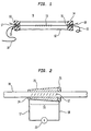
- Fig. 1 illustrates a packaging arrangement 9 wherein a length of fiber 10 including a thermally adjustable grating 11 is disposed within a vessel 12 for thermal isolation such as a cylindrical tube.
- the vessel 12 is sufficiently larger in diameter than the fiber to be spaced from the fiber and thus avoid contact with the grating and yet is sufficiently small in diameter to avoid substantial ambient air currents in the region of the grating.
- the vessel is less than 5 cm in inside diameter and preferably 1 cm or less.
- the vessel 12 is sealed at both ends by elastomeric stoppers 13, 14. It is believed that the vessel could be advantageously coated with a heat reflective coating.
- microcapillary tubes 15, 16 passing through elastomeric stoppers 13, 14 respectively, provide openings for the fiber 10 to pass through the vessel 12.
- Wires 17, 18 can also pass through tubes 15, 16 to permit connection of grating heating elements (not shown) with an electrical source.
- Fig. 2 illustrates an exemplary thermally adjustable grating 11 useful in the embodiment of Fig. 1.
- the grating 11 comprises a sequence of index perturbations 12 in fiber 10.
- the grating 11 is disposed in thermal contact with an electrically controllable heat-transducing body 23, which can be a heat-generating body or a body which actively removes heat.
- the body 23 is typically a heat-generating body such as a resistive film on the fiber.
- the body 23 can be uniform in resistance along the grating 11 to provide uniform heating of the grating and thus permit adjustment of the grating center wavelength.
- the body 23 can vary in local resistance along the grating to provide different heating at different local regions of the grating and thereby permit adjustment of the grating bandwidth.
- a pair of electrodes 24, 25 provides electrical contact with wires 17, 18 from an electrical source 26.
- the device is packaged as depicted in Fig. 1 with a package comprising a thin polyethylene tube (1 cm dia.) with silicone rubber seals on its ends. The tube extended 2 cm beyond either end of the grating. Glass microcapillary tubes inserted in holes in the rubber seals allow the fiber to be inserted into the plastic tube. Electrical connection to the fiber is made near the rubber seals. Passing current through the metal coating causes Joule heating of the fiber. Primarily through the thermo-optic effect, this heating causes a shift peak of the Bragg resonance.
- the package performs several important functions (i) it reduces the rate of heat flow from the fiber to the surroundings, thereby increasing the efficiency of the devices, (ii) it reduces temporal jitter of the reflection peak that arises from uncontrolled, time dependent flow of heat from the fiber to the surroundings and (iii) it eliminates variations in temperature that can arise from spatially non-uniform heat flow out of the fiber.
- the temporal tuning stability and repeatability, preservation of spectral characteristics, and low power consumption are significantly better than those of previously reported gratings that use a similar design, but do not incorporate the thermal isolation package.
- Fig. 3 is a graphical illustration comparing the reflectivity spectrum of the above-described packaged thermally adjustable grating with that of an unpackaged similar thermally adjustable grating (both are operated at an applied voltage of 2.5 V). As can be seen, the grating with the package has a characteristic more closely approximately the ideal, particularly at the long wavelength edge.
- Heat transport from a heated optical fiber device can occur through three modes: radiation, conduction, and convection.
- Convection arises from movement of the medium in contact with the fiber device, typically air. It is desirable to minimize convective heat transport for several reasons.
- convection can strongly augment heat transport.
- convection can add significantly to temporal variations in the device performance. For example, if the velocity of air flowing around the fiber device changes, so will the rate of heat transport away from the fiber. This will change the temperature profile of the device and degrade the device stability. Convection can also lead to instabilities when flow is turbulent.
- the Prandl number is reported as 0.71. All these values come from Krieth & Black, p. 520. One can see that the rate of heat loss, which depends on the Nusselt number, changes strongly with the flow rate of air across a device, and approximately as the 1/3 to 1/2 power of the velocity of air far from the fiber. Suppose the rate heat generation at the fiber surface (q) over a length of fiber (L) is a uniform, constant value q/L.
- Tf the temperature of the fiber
- T ⁇ the ambient temperature far from the fiber.
- Grashof number ⁇ g ⁇ 2 ( T f - T ⁇ ) L 2 ⁇ 2 (pp.
- Kreith and Black give correlations for an air space between two vertical plates separated by a distance b and with a temperature difference DT.
- the Nusselt number is unity for Gr ⁇ 2000 for a correlation from a study by M. Jacob (M. Jacob, "Free Heat Convection Through Enclosed Plane Gas Layers," Trans. ASME. vol. 68, pp. 189-94, April 1946.).
- a study by Emery and Chu gives a Nusselt number of unity for Rayleigh numbers less than 1000 (A. Emery and N. C. Chu, "Heat Transfer Across Vertical Layers," J. Heat Transfer, vol. 87, no. 1, pp.
- Equating Gr to 1-2 x 10 3 gives a value of b of ⁇ 3-6 mm, or an enclosure diameter on the order of a centimeter. This is a realizable diameter for a commercial device.
- the fiber device can easily be packaged in a cylinder of that size or even somewhat smaller.
Landscapes
- Physics & Mathematics (AREA)
- Optics & Photonics (AREA)
- General Physics & Mathematics (AREA)
- Nonlinear Science (AREA)
- Electromagnetism (AREA)
- Engineering & Computer Science (AREA)
- Computer Networks & Wireless Communication (AREA)
- Signal Processing (AREA)
- Manufacturing & Machinery (AREA)
- Plasma & Fusion (AREA)
- Light Guides In General And Applications Therefor (AREA)
- Diffracting Gratings Or Hologram Optical Elements (AREA)
- Optical Fibers, Optical Fiber Cores, And Optical Fiber Bundles (AREA)
- Mechanical Light Control Or Optical Switches (AREA)
Applications Claiming Priority (2)
| Application Number | Priority Date | Filing Date | Title |
|---|---|---|---|
| US09/241,460 US6351585B1 (en) | 1998-10-30 | 1999-02-02 | Thermally adjustable optical fiber grating device with packaging for enhanced performance |
| US241460 | 2005-09-30 |
Publications (1)
| Publication Number | Publication Date |
|---|---|
| EP1026540A1 true EP1026540A1 (fr) | 2000-08-09 |
Family
ID=22910777
Family Applications (1)
| Application Number | Title | Priority Date | Filing Date |
|---|---|---|---|
| EP00300565A Withdrawn EP1026540A1 (fr) | 1999-02-02 | 2000-01-26 | Réseau thermiquement accordable à fibre optique comprenant boitier pour performance améliorée |
Country Status (3)
| Country | Link |
|---|---|
| US (1) | US6351585B1 (fr) |
| EP (1) | EP1026540A1 (fr) |
| JP (1) | JP4024978B2 (fr) |
Cited By (7)
| Publication number | Priority date | Publication date | Assignee | Title |
|---|---|---|---|---|
| FR2828289A1 (fr) * | 2001-08-06 | 2003-02-07 | Cit Alcatel | Compensateur de dispersion large bande accordable |
| US6763043B2 (en) | 1998-12-04 | 2004-07-13 | Cidra Corporation | Tunable grating-based dispersion compensator |
| US6792009B2 (en) | 1998-12-04 | 2004-09-14 | Cidra Corporation | Tunable grating-based channel filter parking device |
| EP2060456A1 (fr) * | 2007-11-14 | 2009-05-20 | Goodrich Corporation | Algorithme pour déterminer le refroidissement de roue et de frein |
| EP2111678A4 (fr) * | 2007-02-02 | 2013-07-03 | Finisar Corp | Emballage stabilisant la temperature pour composants optoelectroniques dans un module d'emetteur |
| CN111504854A (zh) * | 2020-04-13 | 2020-08-07 | 中国矿业大学 | 一种牛顿流体粘度的温差型测量装置及测量方法 |
| CN112946813A (zh) * | 2021-02-22 | 2021-06-11 | 西安石油大学 | 一种光纤光栅的封装结构 |
Families Citing this family (29)
| Publication number | Priority date | Publication date | Assignee | Title |
|---|---|---|---|---|
| US6941044B2 (en) * | 2001-07-25 | 2005-09-06 | Teraxion Inc. | Tunable optical structure for the compensation of chromatic dispersion in a light signal |
| US6879755B2 (en) * | 2001-07-25 | 2005-04-12 | Teraxion Inc. | Optical structure for the compensation of chromatic dispersion and dispersion slope in a light signal |
| CA2369953A1 (fr) * | 2002-01-28 | 2003-07-28 | Jds Uniphase Inc. | Compensateur de dispersion pour fibres optiques a reseau de bragg a reglage thermique |
| AU2003203087A1 (en) * | 2002-02-07 | 2003-09-02 | Teraxion Inc. | Power efficient assemblies for applying a temperature gradient to a refractive index grating |
| US6847763B2 (en) * | 2002-12-17 | 2005-01-25 | Fitel U.S.A. Corp | Colorless tunable dispersion compensator |
| US8792531B2 (en) * | 2003-02-25 | 2014-07-29 | Finisar Corporation | Optical beam steering for tunable laser applications |
| US7580639B2 (en) * | 2003-12-29 | 2009-08-25 | Verizon Business Global Llc | Characterization and control of optical dispersion compensating element |
| US6950578B1 (en) | 2004-05-28 | 2005-09-27 | Fitel Usa Corp. | Highly index-sensitive optical devices including long period fiber gratings |
| WO2008080171A1 (fr) * | 2006-12-22 | 2008-07-03 | Finisar Corporation | Émetteur optique comportant un laser accordable à modulation directe et un élément de remise en forme de spectre optique périodique |
| US7941057B2 (en) * | 2006-12-28 | 2011-05-10 | Finisar Corporation | Integral phase rule for reducing dispersion errors in an adiabatically chirped amplitude modulated signal |
| US8131157B2 (en) | 2007-01-22 | 2012-03-06 | Finisar Corporation | Method and apparatus for generating signals with increased dispersion tolerance using a directly modulated laser transmitter |
| US7991291B2 (en) * | 2007-02-08 | 2011-08-02 | Finisar Corporation | WDM PON based on DML |
| US8027593B2 (en) | 2007-02-08 | 2011-09-27 | Finisar Corporation | Slow chirp compensation for enhanced signal bandwidth and transmission performances in directly modulated lasers |
| US8204386B2 (en) | 2007-04-06 | 2012-06-19 | Finisar Corporation | Chirped laser with passive filter element for differential phase shift keying generation |
| US7991297B2 (en) | 2007-04-06 | 2011-08-02 | Finisar Corporation | Chirped laser with passive filter element for differential phase shift keying generation |
| US7778295B2 (en) * | 2007-05-14 | 2010-08-17 | Finisar Corporation | DBR laser with improved thermal tuning efficiency |
| US8160455B2 (en) | 2008-01-22 | 2012-04-17 | Finisar Corporation | Method and apparatus for generating signals with increased dispersion tolerance using a directly modulated laser transmitter |
| US8260150B2 (en) | 2008-04-25 | 2012-09-04 | Finisar Corporation | Passive wave division multiplexed transmitter having a directly modulated laser array |
| US8331745B2 (en) * | 2009-03-18 | 2012-12-11 | Teraxion Inc. | Assembly for applying a temperature gradient to a refractive index grating and chromatic dispersion compensator |
| US8199785B2 (en) * | 2009-06-30 | 2012-06-12 | Finisar Corporation | Thermal chirp compensation in a chirp managed laser |
| US9217681B2 (en) | 2009-07-16 | 2015-12-22 | Hamidreza Alemohammad | Optical fiber sensor and methods of manufacture |
| US20130062530A1 (en) * | 2011-09-08 | 2013-03-14 | Yu Chih CHANG | Biochemical material detection system |
| US11464451B1 (en) | 2020-03-11 | 2022-10-11 | Huxley Medical, Inc. | Patch for improved biometric data capture and related processes |
| US11660005B1 (en) | 2021-06-04 | 2023-05-30 | Huxley Medical, Inc. | Processing and analyzing biometric data |
| US12178552B1 (en) | 2021-06-04 | 2024-12-31 | Huxley Medical, Inc. | Systems and processes for detecting oxygen saturation and compensating for skin tone variation |
| US12279853B1 (en) | 2021-08-24 | 2025-04-22 | Huxley Medical, Inc. | Photoplethysmography sensors and processes |
| US12114980B1 (en) | 2021-08-24 | 2024-10-15 | Huxley Medical, Inc. | Photoplethysmography sensors and processes |
| US12575741B1 (en) | 2024-04-15 | 2026-03-17 | Huxley Medical, Inc. | Systems and processes for detecting oxygen saturation and compensating for skin tone variation |
| USD1123167S1 (en) | 2024-09-09 | 2026-04-21 | Huxley Medical, Inc. | Wearable medical device |
Citations (7)
| Publication number | Priority date | Publication date | Assignee | Title |
|---|---|---|---|---|
| US5367589A (en) * | 1993-10-22 | 1994-11-22 | At&T Bell Laboratories | Optical fiber package |
| JPH08286040A (ja) * | 1995-04-17 | 1996-11-01 | Sumitomo Electric Ind Ltd | 光ファイバ型回折格子 |
| EP0770890A1 (fr) * | 1995-10-23 | 1997-05-02 | Fujikura Ltd. | Filtre à fibre optique |
| JPH10206620A (ja) * | 1997-01-21 | 1998-08-07 | Oki Electric Ind Co Ltd | 周期変調回折格子 |
| JPH10221658A (ja) * | 1997-02-04 | 1998-08-21 | Nippon Telegr & Teleph Corp <Ntt> | 波長可変ファイバグレーティングフィルタ |
| EP0867736A2 (fr) * | 1997-03-26 | 1998-09-30 | Jds Fitel Inc. | Procédé et dispositif pour accorder la longueur d'ondes et la bande passante d'un réseau de diffraction optique |
| WO1998059267A1 (fr) * | 1997-06-19 | 1998-12-30 | Uniphase Fibre Components Pty, Limited | Boitier pour reseau de bragg, stable en temperature et a post-reglage permettant un ajustement precis de la frequence centrale |
Family Cites Families (6)
| Publication number | Priority date | Publication date | Assignee | Title |
|---|---|---|---|---|
| US5159601A (en) * | 1991-07-17 | 1992-10-27 | General Instrument Corporation | Method for producing a tunable erbium fiber laser |
| US5502782A (en) * | 1995-01-09 | 1996-03-26 | Optelecom, Inc. | Focused acoustic wave fiber optic reflection modulator |
| US5671307A (en) * | 1995-04-10 | 1997-09-23 | Universite Laval | Use of a temperature gradient to impose a chirp on a fibre bragg grating |
| US5757540A (en) * | 1996-09-06 | 1998-05-26 | Lucent Technologies Inc. | Long-period fiber grating devices packaged for temperature stability |
| US6011886A (en) * | 1997-10-16 | 2000-01-04 | Lucent Technologies Inc. | Recoatable temperature-insensitive long-period gratings |
| US5987200A (en) * | 1997-10-27 | 1999-11-16 | Lucent Technologies Inc. | Device for tuning wavelength response of an optical fiber grating |
-
1999
- 1999-02-02 US US09/241,460 patent/US6351585B1/en not_active Expired - Lifetime
-
2000
- 2000-01-26 EP EP00300565A patent/EP1026540A1/fr not_active Withdrawn
- 2000-02-02 JP JP2000024572A patent/JP4024978B2/ja not_active Expired - Fee Related
Patent Citations (7)
| Publication number | Priority date | Publication date | Assignee | Title |
|---|---|---|---|---|
| US5367589A (en) * | 1993-10-22 | 1994-11-22 | At&T Bell Laboratories | Optical fiber package |
| JPH08286040A (ja) * | 1995-04-17 | 1996-11-01 | Sumitomo Electric Ind Ltd | 光ファイバ型回折格子 |
| EP0770890A1 (fr) * | 1995-10-23 | 1997-05-02 | Fujikura Ltd. | Filtre à fibre optique |
| JPH10206620A (ja) * | 1997-01-21 | 1998-08-07 | Oki Electric Ind Co Ltd | 周期変調回折格子 |
| JPH10221658A (ja) * | 1997-02-04 | 1998-08-21 | Nippon Telegr & Teleph Corp <Ntt> | 波長可変ファイバグレーティングフィルタ |
| EP0867736A2 (fr) * | 1997-03-26 | 1998-09-30 | Jds Fitel Inc. | Procédé et dispositif pour accorder la longueur d'ondes et la bande passante d'un réseau de diffraction optique |
| WO1998059267A1 (fr) * | 1997-06-19 | 1998-12-30 | Uniphase Fibre Components Pty, Limited | Boitier pour reseau de bragg, stable en temperature et a post-reglage permettant un ajustement precis de la frequence centrale |
Non-Patent Citations (4)
| Title |
|---|
| G. W. YOFFE, PETER A. KRUG, F. OUELLETTE, D. A. THORNCRAFT: "Passive temperature-compensating package for optical fiber gratings", XP000534305 * |
| LIMBERGER H G ET AL: "IEEE PHOTONICS TECHNOLOGY LETTERS,US,IEEE INC. NEW YORK", IEEE PHOTONICS TECHNOLOGY LETTERS,US,IEEE INC. NEW YORK, vol. 10, no. 3, 1 March 1998 (1998-03-01), pages 361 - 363, XP000740673, ISSN: 1041-1135 * |
| PATENT ABSTRACTS OF JAPAN vol. 1997, no. 03 31 March 1997 (1997-03-31) * |
| PATENT ABSTRACTS OF JAPAN vol. 1998, no. 13 30 November 1998 (1998-11-30) * |
Cited By (8)
| Publication number | Priority date | Publication date | Assignee | Title |
|---|---|---|---|---|
| US6763043B2 (en) | 1998-12-04 | 2004-07-13 | Cidra Corporation | Tunable grating-based dispersion compensator |
| US6792009B2 (en) | 1998-12-04 | 2004-09-14 | Cidra Corporation | Tunable grating-based channel filter parking device |
| FR2828289A1 (fr) * | 2001-08-06 | 2003-02-07 | Cit Alcatel | Compensateur de dispersion large bande accordable |
| EP1283433A3 (fr) * | 2001-08-06 | 2003-02-19 | Alcatel | Compensateur de dispersion large bande accordable |
| EP2111678A4 (fr) * | 2007-02-02 | 2013-07-03 | Finisar Corp | Emballage stabilisant la temperature pour composants optoelectroniques dans un module d'emetteur |
| EP2060456A1 (fr) * | 2007-11-14 | 2009-05-20 | Goodrich Corporation | Algorithme pour déterminer le refroidissement de roue et de frein |
| CN111504854A (zh) * | 2020-04-13 | 2020-08-07 | 中国矿业大学 | 一种牛顿流体粘度的温差型测量装置及测量方法 |
| CN112946813A (zh) * | 2021-02-22 | 2021-06-11 | 西安石油大学 | 一种光纤光栅的封装结构 |
Also Published As
| Publication number | Publication date |
|---|---|
| JP2000227523A (ja) | 2000-08-15 |
| US6351585B1 (en) | 2002-02-26 |
| JP4024978B2 (ja) | 2007-12-19 |
Similar Documents
| Publication | Publication Date | Title |
|---|---|---|
| US6351585B1 (en) | Thermally adjustable optical fiber grating device with packaging for enhanced performance | |
| EP1030472B1 (fr) | Système de communication optique muni de modules de compensation automatique de la dispersion | |
| US6275629B1 (en) | Optical grating devices with adjustable chirp | |
| US6829415B2 (en) | Optical waveguide devices with electro-wetting actuation | |
| US7043115B2 (en) | Tunable optical filter | |
| US7239778B2 (en) | Active in-fiber optic components powered by in-fiber light | |
| US5619600A (en) | Near-field photon tunneling devices using liquid metal | |
| JP3386417B2 (ja) | 再構成性のためのクラッディング感度を強化した光ファイバ回折格子デバイス | |
| JP2001077756A (ja) | 温度に起因する分散の変動を補償するための自動分散補償モジュールを組み込む光ファイバ通信システム | |
| US6317548B1 (en) | Temperature and optical length control of optical fibers and optical waveguide devices | |
| US6498877B1 (en) | Tunable optical fiber bragg and long period grating | |
| US6879755B2 (en) | Optical structure for the compensation of chromatic dispersion and dispersion slope in a light signal | |
| US6856731B2 (en) | Heat tunable optical devices with linearity compensation | |
| Dabarsyah et al. | Adjustable dispersion-compensation devices with wavelength tunability based on enhanced thermal chirping of fiber Bragg gratings | |
| US6807340B2 (en) | Fiber bragg grating dispersion compensator | |
| CN101581835B (zh) | 一种基于磁致伸缩的啁啾光栅调谐装置 | |
| EP1498752A1 (fr) | Arrangement pour la compensation thermique d'un réseau de diffraction dans une fibre optique | |
| Iodice et al. | Transient analysis of a high-speed thermo-optic modulator integrated in an all-silicon waveguide | |
| Zhang et al. | Programmable all-fiber structured waveshaper based on linearly chirped fiber Bragg grating and digital thermal controller | |
| Rogers et al. | Temperature stabilised operation of tunable fibre grating devices that use distributed on-fibre thin film heaters | |
| US9256065B1 (en) | System and method for compensating thermal dependent loss in variable optical attenuators | |
| WO2000070379A1 (fr) | Filtre reglable en amplitude | |
| US20020181878A1 (en) | Dynamic chromatic dispersion control using coupled optical waveguides | |
| JP2002258070A (ja) | 分散補償ファイバグレーティングモジュール | |
| Eggleton et al. | Temperature stabilized tunable fiber grating devices with integrated on-fiber thin film heaters |
Legal Events
| Date | Code | Title | Description |
|---|---|---|---|
| PUAI | Public reference made under article 153(3) epc to a published international application that has entered the european phase |
Free format text: ORIGINAL CODE: 0009012 |
|
| AK | Designated contracting states |
Kind code of ref document: A1 Designated state(s): DE FR GB IT |
|
| AX | Request for extension of the european patent |
Free format text: AL;LT;LV;MK;RO;SI |
|
| 17P | Request for examination filed |
Effective date: 20010125 |
|
| AKX | Designation fees paid |
Free format text: DE FR GB IT |
|
| 17Q | First examination report despatched |
Effective date: 20070629 |
|
| RAP3 | Party data changed (applicant data changed or rights of an application transferred) |
Owner name: LUCENT TECHNOLOGIES INC. |
|
| STAA | Information on the status of an ep patent application or granted ep patent |
Free format text: STATUS: THE APPLICATION HAS BEEN WITHDRAWN |
|
| 18W | Application withdrawn |
Effective date: 20111104 |