EP1026918A2 - Procédé de sauvegarde pour des connexions de signalisation - Google Patents
Procédé de sauvegarde pour des connexions de signalisation Download PDFInfo
- Publication number
- EP1026918A2 EP1026918A2 EP99116602A EP99116602A EP1026918A2 EP 1026918 A2 EP1026918 A2 EP 1026918A2 EP 99116602 A EP99116602 A EP 99116602A EP 99116602 A EP99116602 A EP 99116602A EP 1026918 A2 EP1026918 A2 EP 1026918A2
- Authority
- EP
- European Patent Office
- Prior art keywords
- layer
- link
- primary
- signalling
- port
- Prior art date
- Legal status (The legal status is an assumption and is not a legal conclusion. Google has not performed a legal analysis and makes no representation as to the accuracy of the status listed.)
- Granted
Links
- 230000011664 signaling Effects 0.000 title claims abstract description 372
- 238000000034 method Methods 0.000 title claims abstract description 82
- 230000002159 abnormal effect Effects 0.000 claims abstract description 52
- 238000012546 transfer Methods 0.000 claims abstract description 34
- 238000004891 communication Methods 0.000 claims description 50
- 238000001514 detection method Methods 0.000 claims description 29
- 238000012544 monitoring process Methods 0.000 claims 23
- 239000010410 layer Substances 0.000 description 297
- 239000003795 chemical substances by application Substances 0.000 description 71
- 241001393742 Simian endogenous retrovirus Species 0.000 description 26
- 239000004820 Pressure-sensitive adhesive Substances 0.000 description 6
- 230000006978 adaptation Effects 0.000 description 3
- 230000005540 biological transmission Effects 0.000 description 3
- 230000000977 initiatory effect Effects 0.000 description 3
- 230000008569 process Effects 0.000 description 3
- 230000009471 action Effects 0.000 description 2
- 239000002356 single layer Substances 0.000 description 2
- 238000012795 verification Methods 0.000 description 2
- TVZRAEYQIKYCPH-UHFFFAOYSA-N 3-(trimethylsilyl)propane-1-sulfonic acid Chemical compound C[Si](C)(C)CCCS(O)(=O)=O TVZRAEYQIKYCPH-UHFFFAOYSA-N 0.000 description 1
- 230000004075 alteration Effects 0.000 description 1
- 238000012937 correction Methods 0.000 description 1
- 230000000694 effects Effects 0.000 description 1
- 239000002346 layers by function Substances 0.000 description 1
- 230000007246 mechanism Effects 0.000 description 1
- 238000012986 modification Methods 0.000 description 1
- 230000004048 modification Effects 0.000 description 1
- 238000012545 processing Methods 0.000 description 1
- 230000004044 response Effects 0.000 description 1
- 239000000126 substance Substances 0.000 description 1
- 230000001360 synchronised effect Effects 0.000 description 1
Images


Classifications
-
- H—ELECTRICITY
- H04—ELECTRIC COMMUNICATION TECHNIQUE
- H04L—TRANSMISSION OF DIGITAL INFORMATION, e.g. TELEGRAPHIC COMMUNICATION
- H04L49/00—Packet switching elements
- H04L49/30—Peripheral units, e.g. input or output ports
- H04L49/3081—ATM peripheral units, e.g. policing, insertion or extraction
-
- H—ELECTRICITY
- H04—ELECTRIC COMMUNICATION TECHNIQUE
- H04Q—SELECTING
- H04Q11/00—Selecting arrangements for multiplex systems
- H04Q11/04—Selecting arrangements for multiplex systems for time-division multiplexing
- H04Q11/0428—Integrated services digital network, i.e. systems for transmission of different types of digitised signals, e.g. speech, data, telecentral, television signals
- H04Q11/0478—Provisions for broadband connections
-
- H—ELECTRICITY
- H04—ELECTRIC COMMUNICATION TECHNIQUE
- H04Q—SELECTING
- H04Q3/00—Selecting arrangements
- H04Q3/0016—Arrangements providing connection between exchanges
- H04Q3/0025—Provisions for signalling
-
- H—ELECTRICITY
- H04—ELECTRIC COMMUNICATION TECHNIQUE
- H04L—TRANSMISSION OF DIGITAL INFORMATION, e.g. TELEGRAPHIC COMMUNICATION
- H04L12/00—Data switching networks
- H04L12/54—Store-and-forward switching systems
- H04L12/56—Packet switching systems
- H04L12/5601—Transfer mode dependent, e.g. ATM
- H04L2012/5625—Operations, administration and maintenance [OAM]
- H04L2012/5627—Fault tolerance and recovery
-
- H—ELECTRICITY
- H04—ELECTRIC COMMUNICATION TECHNIQUE
- H04L—TRANSMISSION OF DIGITAL INFORMATION, e.g. TELEGRAPHIC COMMUNICATION
- H04L12/00—Data switching networks
- H04L12/54—Store-and-forward switching systems
- H04L12/56—Packet switching systems
- H04L12/5601—Transfer mode dependent, e.g. ATM
- H04L2012/5629—Admission control
- H04L2012/563—Signalling, e.g. protocols, reference model
Definitions
- a backup procedure employing standby signalling links for improving signalling performance reliability of interfaces controlled by such links, particularly in a DSS2 asynchronous transfer mode network.
- the physical layer (L1) interfaces directly with a physical transmission medium. It provides for the transparent transmission of a digital data stream across the physical link between network elements.
- the intelligence managing the data stream and protocols residing above the physical layer are transparently conveyed by the physical layer.
- the data link layer (L2) is primarily responsible for providing a reliable communications path across the physical layer on behalf of the network layer. Typically this entails that the link layer perform error detection and in some cases, error correction.
- the data link control functions at this layer establish a peer-to-peer relationship across each physical link between network elements.
- the function of the network layer generally is to provide reliable, in sequence delivery of protocol data between higher layer (e.g., transport layer) entities.
- the network layer must have an end-to-end addressing capability.
- a unique network-layer (end-to-end) address is assigned to each network-layer capable network element, which may communicate with its peers over a route of intermediate elements through the network.
- the network layer also provides call processing functionality.
- Digital subscriber signalling system no. 2 is a well known example of such a network layer protocol.
- the digital subscriber signalling system no. 2 is an asynchronous transfer mode (ATM) protocol which specifies the procedures for establishing, maintaining and clearing of network connections at the user-network interface (UNI) of a broadband integrated service digital network (B-ISDN).
- ATM asynchronous transfer mode
- ITU-T International Telecommunications Union, Telecommunications Standardization Sector
- B-ISDN Broadband Integrated Services Digital Network
- DSS 2 Digital Subscriber Signalling System No. 2
- UNI User-Network Interface
- a signalling link controls multiple interfaces. Failure of the interface carrying the signalling link will result in the tearing down of all calls controlled by the signalling link, even though the interfaces carrying the actual calls are still operational. When non-associated signalling is employed, the reliability of the signalling performance for the interfaces controlled by the signalling link may be unacceptable.
- the present invention improves such reliability by providing a backup procedure employing standby signalling links.
- Proxy Signalling is an optional capability, as specified by the ATM Forum, in ATM UNI Signalling Specification, Version 4.0, af-sig-0061.000, which allows a user known as a proxy signalling agent (PSA), to perform signalling for one or more users that do not support signalling.
- PSA proxy signalling agent
- a single PSA can control a large number of interfaces on different switches in the ATM network.
- the reliability of proxy signalling is improved by using a backup PSA.
- the present invention supports redundant PSAs when they operate in an active and standby fashion; that is, with only one of the PSAs active at any time to provide messages at ATM Layer 3 (i.e. the network layer).
- the present invention applies to the interface between terminal or endpoint equipment and a communications network, such as an ATM network or other connection-based communications system.
- a communications network such as an ATM network or other connection-based communications system.
- the invention when non-associated signalling is used, the invention allows the peer DSS2 (Layer 3) signalling entities at the terminal equipment and ATM Switch to use two ATM Adaptation Layer Service Specific Sublayer (SAAL Layer 2, or datalink layer) connections, i.e. an active and a standby.
- SAAL Layer 2, or datalink layer ATM Adaptation Layer Service Specific Sublayer
- the invention allows a redundant pair of PSAs operating in an active/standby fashion to control the same interfaces on an ATM switch using different DSS2 signalling links from each PSA, but terminating on one DSS2 link in the ATM switch.
- the invention thus enables the Layer 3 entity at the ATM Switch to use up to four Layer 2 connections, i.e. two connections to the active PSA and two connections to the standby PSA. In both cases, only one of the Layer 2 connections is active at any time to carry signalling messages.
- the invention provides a method of improving the signalling performance reliability of an interface between two signalling agents and a network element (such as an ATM switch in a DSS2 asynchronous transfer mode network).
- a network element such as an ATM switch in a DSS2 asynchronous transfer mode network.
- a Layer 2 connection (the "primary link") is established between a first Layer 2 port of the signalling agent and a first Layer 2 port of the network element; and, a Layer 2 connection (the "primary backup link”) is established between a second Layer 2 port of the signalling agent and a second Layer 2 port of the network element.
- the Layer 2 ports are coupled to Layer 3 segments of the signalling agent and the network element respectively, in accordance with established network communication protocols.
- the primary link is maintained in an active state in which all signalling messages directed to the interface are transferred between the Layer 3 segments over the primary link.
- the primary backup link is maintained in a standby state, such that it is active between the second set of Layer 2 ports, but inactive between the Layer 3 segments.
- the primary link Upon abnormal operation of the primary link, the primary link is temporarily switched into an inactive state to prevent further transfer over the primary link of signalling messages directed to the interface; and, the primary backup link is switched into an active state in which all signalling messages directed to the interface are transferred between the Layer 3 segments over the primary backup link.
- a Layer 2 connection (the "primary link") is established between a first Layer 2 port of the primary signalling agent and a first Layer 2 port of the network element; a Layer 2 connection (the “primary backup link”) is established between a second Layer 2 port of the primary signalling agent and a second Layer 2 port of the network element; a Layer 2 connection (the “secondary link”) is established between a first Layer 2 port of the secondary signalling agent and a third Layer 2 port of the network element; and, a Layer 2 connection (the “secondary backup link”) is established between a second Layer 2 port of the secondary signalling agent and a fourth Layer 2 port of the network element.
- the Layer 2 ports are coupled to Layer 3 segments of the signalling agents and the network element respectively, in accordance with established network communication protocols.
- the primary signalling agent is active, and the primary link is maintained in an active state in which all signalling messages directed to the interface are transferred between the Layer 3 segments over the primary link.
- the primary backup link is maintained in a standby state in which the primary backup link is active between the primary signalling agent second Layer 2 port and the network element second Layer 2 port, but inactive between the Layer 3 segments.
- the secondary link is maintained in a standby state in which the secondary link is active between the secondary signalling agent first Layer 2 port and the network element third Layer 2 port but inactive between the Layer 3 segments; and, the secondary backup link is maintained in a standby state in which the secondary backup link is active between the secondary signalling agent second Layer 2 port and the network element fourth Layer 2 port but inactive between the Layer 3 segments.
- the primary link Upon abnormal operation of the primary link and during normal operation of the Layer 2 connections to the secondary signalling agents, the primary link is temporarily switched into an inactive state to prevent further transfer over the primary link of signalling messages directed to the interface; and the primary backup link is switched into an active state in which all signalling messages directed to the interface are transferred between the Layer 3 segments over the primary backup link.
- the secondary link and the secondary backup link are maintained in their respective standby states.
- the links to the primary agent are temporarily switched into an inactive state to prevent further transfer over the primary link of signalling messages directed to the interface; and the secondary link is switched into an active state in which all signalling messages directed to the interface are transferred between the Layer 3 segments over the secondary link.
- the secondary backup link is maintained in a standby state.
- the invention provides a method of improving the signalling performance reliability of an interface between a signalling agent and a network element.
- a Layer 2 primary link is established between a first Layer 2 port of the signalling agent and a first Layer 2 port of the network element.
- the signalling agent first Layer 2 port is further coupled to a Layer 3 segment of the signalling agent, and the network element first Layer 2 port is further coupled to a Layer 3 segment of the network element.
- a Layer 2 primary backup link is established between a second Layer 2 port of the signalling agent and a second Layer 2 port of the network element.
- the signalling agent second Layer 2 port is further coupled to the Layer 3 segment of the signalling agent, and the network element second Layer 2 port is further coupled to the Layer 3 segment of the network element.
- the primary link During normal operation of the primary link, the primary link is maintained in an active state in which all signalling messages directed to the interface are transferred between the Layer 3 segments over the primary link; with the primary backup link being maintained in a standby state in which the primary backup link is active between the second Layer 2 ports but inactive between the Layer 3 segments.
- the primary link Upon abnormal operation of the primary link, the primary link is maintained in an inactive state to prevent further transfer over the primary link of signalling messages directed to the interface; and, the primary backup link is maintained in an active state in which all signalling messages directed to the interface are transferred between the Layer 3 segments over the primary backup link.
- the invention provides a method of improving the signalling performance reliability of an interface between first and second network elements.
- a Layer 2 primary link is established between a first Layer 2 port of the first network element and a first Layer 2 port of the second network element.
- the first network element first Layer 2 port is further coupled to a Layer 3 segment of the first network element and the second network element first Layer 2 port is further coupled to a Layer 3 segment of the second network element.
- a Layer 2 primary backup link is established between a second Layer 2 port of the first network element and a second Layer 2 port of the second network element.
- the first network element second Layer 2 port is further coupled to the Layer 3 segment of the first network element
- the second network element second Layer 2 port is further coupled to the Layer 3 segment of the second network element.
- the primary link During normal operation of the primary link, the primary link is maintained in an active state in which all signalling messages directed to the interface are transferred between the Layer 3 segments over the primary link; and, the primary backup link is maintained in a standby state in which the primary backup link is active between the second Layer 2 ports but inactive between the Layer 3 segments.
- the primary link Upon abnormal operation of the primary link, the primary link is maintained in an inactive state to prevent further transfer over the primary link of signalling messages directed to the interface; and, the primary backup link is maintained in an active state in which all signalling messages directed to the interface are transferred between the Layer 3 segments over the primary backup link.
- the invention provides a method of improving the signalling performance reliability of an interface between a first signalling agent, a second signalling agent and a network element.
- a primary link is established between a first Layer 2 port of the first signalling agent and a first Layer 2 port of the network element.
- the first signalling agent first Layer 2 port is further coupled to a Layer 3 segment of the first signalling agent, and the network element first Layer 2 port is further coupled to a Layer 3 segment of the network element.
- a secondary link is established between a first Layer 2 port of the second signalling agent and a second Layer 2 port of the network element.
- the second signalling agent first Layer 2 port is further coupled to a Layer 3 segment of the second signalling agent, and the network element second Layer 2 port is further coupled to the Layer 3 segment of the network element.
- the primary link is maintained in an active state in which all signalling messages directed to the interface are transferred between the Layer 3 segments over the primary link; and, the secondary link is maintained in a standby state in which the secondary link is active between the second signalling agent first Layer 2 port and the network element second Layer 2 port but inactive between the Layer 3 segments.
- the primary link Upon abnormal operation of the first signalling agent and during normal operation of the second signalling agent the primary link is maintained in an inactive state to prevent further transfer over the primary link of signalling messages directed to the interface; and, the secondary link is maintained in an active state in which all signalling messages directed to the interface are transferred between the Layer 3 segments over the secondary link.
- the invention provides a method of improving the signalling performance reliability of an interface between a signalling agent and a connection-based communications system.
- a datalink layer primary link is established between a first datalink layer port of the signalling agent and a first datalink layer port of the communications systems.
- the signalling agent first datalink layer port is further coupled to a network layer segment of the signalling agent, and the communications system first datalink layer port is further coupled to a network layer segment of the communications system.
- a datalink layer primary backup link is established between a second datalink layer port of the signalling agent and a second datalink layer port of the communications system.
- the signalling agent second datalink layer port is further coupled to the network layer segment of the signalling agent, and the communications system second datalink layer port is further coupled to the network layer segment of the communications system.
- the primary link is maintained in an active state in which all signalling messages directed to the interface are transferred between the network layer segments over the primary link; and, the primary backup link is maintained in a standby state in which the primary backup link is active between the second datalink layer ports but inactive between the network layer segments.
- the primary link Upon abnormal operation of the primary link, the primary link is maintained in an inactive state to prevent further transfer over the primary link of signalling messages directed to the interface; and, the primary backup link is maintained in an active state in which all signalling messages directed to the interface are transferred between the network layer segments over the primary backup link.
- the invention provides a method of improving the signalling performance reliability of an interface between a first signalling agent, a second signalling agent and a connection-based communications system.
- a primary link is established between a first datalink layer port of the first signalling agent and a first datalink layer port of the communications system.
- the first signalling agent first datalink layer port is further coupled to a network layer segment of the first signalling agent
- the communications system first datalink layer port is further coupled to a network layer segment of the communications system.
- a secondary link is established between a first datalink layer port of the second signalling agent and a second datalink layer port of the communications system.
- the second signalling agent first datalink layer port is further coupled to a network layer segment of the second signalling agent, and the communications system second datalink layer port is further coupled to the network layer segment of the communications system.
- the primary link is maintained in an active state in which all signalling messages directed to the interface are transferred between the network layer segments over the primary link; and, the secondary link is maintained in a standby state in which the secondary link is active between the second signalling agent first datalink layer port and the communications system second datalink layer port but inactive between the network layer segments.
- the primary link Upon abnormal operation of the first signalling agent and during normal operation of the second signalling agent, the primary link is maintained in an inactive state to prevent further transfer over the primary link of signalling messages directed to the interface; and, the secondary link is maintained in an active state in which all signalling messages directed to the interface are transferred between the network layer segments over the secondary link.
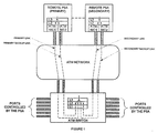
- Figure 1 depicts a pair of redundant proxy signalling agents, both having backup links in accordance with the invention.
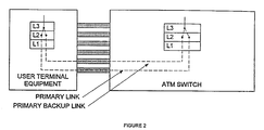
- Figure 2 provides an example of non-associated signalling with a backup link in accordance with the invention.
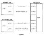
- Figure 3 depicts an architecture for implementing a backup procedure with redundant proxy signalling agents, in accordance with the invention.
- Figure 4 depicts an architecture for implementing a backup procedure with a non-redundant signalling agent, in accordance with the invention.
- Figure 5 is a table particularizing the Layer 3 timer T321 used in the preferred embodiment.
- Figure 6 is a table particularizing the Layer 2 connection timer TWait used in the preferred embodiment.
- Figure 7 particularizes the link status information element is used to convey the desired status of a Layer 2 connection.
- the invention solves two problems, as previously indicated.
- the first problem is to improve the reliability of signalling links when one signalling link is used to control multiple interfaces on a network element, for example, a switch or router.
- the second problem is to allow a redundant pair of Proxy Signalling Agents, which are operating in an active/standby fashion, to control the same interfaces on the network element using different signalling links from each PSA, but terminating on one signalling link in the network element.
- the first problem is solved by using two link layer or Layer 2 connections between peer network layer or Layer 3 entities. While both connections may be active at Layer 2, only one of the Layer 2 connections can be used at any one time to carry signalling messages between the peer Layer 3 entities. Initially one connection is made active for use by Layer 3, and when that connection fails a switch-over protocol is used to bring the other connection into service. Layer 3 continues to use this connection even after the first connection is reconnected at Layer 2. Thus, a switch-over only occurs when a failure occurs on the Layer 2 connection that is used by the Layer 3 entity.
- the second problem is solved by connecting the Layer 2 connections from each PSA to a single Layer 3 entity on the network element, for instance an ATM switch, and defining a procedure for switching between the connections. Since only one PSA can be active at any one time, only the Layer 2 connection to the active PSA can be used to carry signalling messages for Layer 3. This solution also supports the use of backup Layer 2 connections from each PSA to the ATM Switch.
- FIG. 1 shows an example of proxy signalling using a backup procedure in accordance with the invention.
- a redundant pair of "proxy signalling agents” operate in an active and standby fashion. Only one of the PSAs is active at any given time.
- the active PSA controls one or more ports on the ATM switch.
- the other PSA becomes active and takes over the control of the ports, as hereinafter explained. Throughout the take over process, all stable calls on these ports are maintained.
- FIG. 2 depicts an example of the backup procedure of the present invention as applied to non-associated signalling.
- the User Terminal Equipment has one or more facilities to the ATM switch which are controlled by a single Layer 3 (L3) signalling entity.
- the Layer 3 entity has two Layer 2 (L2) connections created on two physically separate facilities. Signalling messages are sent over one Layer 2 connection (the "primary link”) and the other (the “primary backup link”) acts as a standby. When the active Layer 2 connection fails, the standby is made active.
- FIG. 3 depicts the architecture of the backup procedure when redundant proxy signalling agents are used to control one or more ports on an ATM Switch.
- the primary PSA is the agent that is designated to be active when the system is first initialized.
- the secondary PSA (if present) assumes a standby role when the system is first initialized.
- a redundant pair of Layer 2 connections is supported from each agent.
- the Layer 2 connections to the primary PSA are provisioned as the primary and primary backup links, and the Layer 2 connections to the secondary PSA are provisioned as the secondary and secondary backup links.
- the backup links to each PSA are optional. If these backup links are used, they increase reliability and reduce the need to switch between agents when a link fails, since the process of switching between agents is more disruptive than switching between links to the same agent.
- This backup procedure requires that the PSA redundancy procedure keep the Layer 3 entity in the standby PSA synchronized with the Layer 3 entity in the active PSA.
- Figure 4 depicts the architecture of the backup procedure when non-redundant signalling agents are used. In this case, only the primary and primary backup links are required.
- This Layer 2 connection is provisioned between the ATM switch and the user terminal equipment or primary PSA.
- the Layer 3 entity is functionally equivalent to a signalling link as defined by the ITU-T in the aforementioned Q.2931 publication. This allows the same Layer 3 entity to operate with peer Layer 3 entities that do not support this procedure.
- the primary link is always present.
- This Layer 2 connection is provisioned between the ATM switch and the primary PSA, and serves as a backup for the primary link. It is used when a failure is detected on the primary link.
- the protocol used to switch between the primary and primary backup links is described below.
- This Layer 2 connection is provisioned between the ATM switch and the secondary PSA. It is used only when the secondary PSA becomes active.
- the protocol used to switch between the primary and secondary links is described below.
- This Layer 2 connection is provisioned between the ATM switch and the secondary PSA, and serves as a backup for the secondary link.
- the protocol used to switch between the secondary and secondary backup links is described below.
- the designations as primary link, primary backup link, secondary link and secondary backup link are agreed upon at subscription time by both sides of the interface. All connections are functionally equivalent in providing signalling for an ATM Layer 3 entity and only one of the connections is active at any given time to carry signalling messages for the Layer 3 entity.
- the order in which a Layer 2 connection is selected to provide signalling messages to Layer 3 on initiation or when all connections are out of service is: primary link, primary backup link, secondary link and secondary backup link respectively. That is, the primary link has the highest priority and the secondary backup link has the lowest priority with respect to link selection.
- Each Layer 2 connection is an assured mode signalling ATM adaptation layer (AAL) connection established between the peer Layer 2 entities.
- AAL ATM adaptation layer
- Each Layer 2 connection may be in one of the following states with respect to its Layer 3 entity:
- a Layer 2 connection is in the IS state when it is active at Layer 2 and is being used to carry Layer 3 signalling messages. Only one of the Layer 2 connections that serve a particular Layer 3 entity can be in the IS state at any one time.
- the IS state is an invalid state for a Layer 2 connection connected to a standby PSA.
- a Layer 2 connection is in the STBY state when it is active at Layer 2 but is not being used to carry Layer 3 signalling messages.
- a Layer 2 connection is in the CON state when it is inactive at Layer 2 and is periodically requested by Layer 3 to establish the connection.
- the connection is placed in the STBY state either when an AAL_ESTABLISH-confirm or when an AAL_ESTABLISH-indication primitive is received from Layer 2, as hereinafter explained.
- a Layer 2 connection is in the OOS state when it is inactive at Layer 2. While in the OOS state, the response to an invitation to a connection establishment is met with the transmission of an AAL_RELEASE-request, as hereinafter explained.
- the OOS state is entered when the connection is administratively disabled or when it is placed in this state by Layer 3 to eliminate it as candidate for the active link. If the connection enters the OOS state after being administratively disabled, then it is placed in the OOS state only after it is administratively enabled.
- a timer (TWait) is started for the connection, as hereinafter explained. On expiry of TWait, the connection is placed in the CON state.
- Each Layer 3 entity in the ATM switch, user terminal equipment or PSA is in one of the following states at any one time:
- a Layer 3 entity is in the Up state if it is administratively enabled and one of its Layer 2 connections is in the IS state.
- a Layer 3 entity can only exchange messages with its peer entity when it is in the Up state. This state is invalid for a Layer 3 entity in the standby PSA, since it cannot bring any of its connections to the IS state.
- a Layer 3 entity is in the Connecting state if it is administratively enabled and in the process of bringing up one of its Layer 2 connections to the IS state.
- the Layer 3 entity is placed in the Up state when one of its Layer 2 connections enters the IS state.
- When a Layer 3 entity is placed in the Connecting state it places all of its administratively enabled Layer 2 connections in the CON state.
- a Layer 3 entity in the standby PSA must not try to bring any of its connections to the IS state, but must immediately be placed in the Standby state when one of its connections is placed in the STBY state.
- a Layer 3 entity is in the Standby state if it is administratively enabled; if none of its Layer 2 connections are in the IS state, and if at least one of its Layer 2 connections is in the STBY state. This state is only valid for a Layer 3 entity in the standby PSA.
- a Layer 3 entity set is in the Down state if it is administratively disabled, or if it is administratively enabled and all of its Layer 2 connections are in the OOS state. When a Layer 3 entity is administratively disabled, all of its Layer 2 connections will be administratively disabled and hence placed in the OOS state.
- the procedures for establishing and releasing of the signalling AAL connection are applied in accordance with the aforementioned ITU-T, Q.2931 DSS2 Signalling Specification.
- the switch-over between the primary link and primary backup link, or between the secondary link and secondary backup link can be initiated by either signalling entity and uses the same procedure.
- the switch-over between the primary and secondary links can only be initiated by the signalling entity in the PSA.
- the switch-over protocol uses SERVICE and SERVICE ACKNOWLEDGE messages to bring the STBY link into the IS condition, and to avoid any possible deadlock condition.
- the messages are sent as parameter data of the AAL_UNITDATA primitive. The format and coding of the messages is described below. These messages can only be sent or received when the Layer 2 connection is in the STBY or IS state. Receipt of these messages in any other state is ignored.
- a Layer 3 entity in the ATM switch and user terminal equipment brings up the primary link first. More particularly, the Layer 3 entity in the active PSA brings up the primary link first if it is the primary PSA, and brings up the secondary link first if it is the secondary PSA. At this stage, all Layer 2 connections are in the CON state.
- a Layer 3 entity uses the following procedure to bring a Layer 2 connection to the IS state. This procedure is not used by a Layer 3 entity in the standby PSA. The standby PSA does not attempt to bring any of its connections to the IS state, but brings its connections to the STBY state only.
- L1 and L2 be any two Layer 2 connections that are used by the Layer 3 entity such that L1 ⁇ L2.
- L1 and L2 are connections from the set ⁇ primary link, primary backup link, secondary link, secondary backup link ⁇ for the Layer 3 entity in the ATM switch;
- L1 and L2 are connections from the set ⁇ primary link, primary backup ⁇ for the user terminal equipment and primary PSA;
- L1 and L2 are connections from the set ⁇ secondary link, secondary backup link ⁇ for the secondary PSA.
- T321 is stopped. This message is received only by the Layer 3 entity on the ATM switch.
- the SERVICE messages are not sent on the connection and the connection goes from the OOS state to the IS state when the connection is established to the far end. This also applies to the primary PSA when the secondary PSA does not exist.
- the Layer 3 entity uses the SERVICE and SERVICE ACKNOWLEDGE messages to verify the status of the link once it is active at Layer 2.
- the SERVICE ACKNOWLEDGE message optionally includes the status of all other Layer 2 connections provisioned at the remote Layer 3 entity.
- a connection active at Layer 2 (i.e. in the IS or STBY state) is declared as failed when an AAL_RELEASE-indication primitive is received from Layer 2.
- a failed connection in the IS state is placed in the OOS state, and a failed connection in the STBY state is placed in the CON state, as determined by the switch-over procedure.
- a failed connection in the STBY state is placed in the CON state.
- an AAL_RELEASE-request primitive is sent on the connection and it is placed in the OOS state.
- L1 and L2 represent either the primary link and primary backup link; or, the secondary link and secondary backup link.
- L1 represents a Layer 2 connection to the active PSA
- L2 represents a Layer 2 connection to the standby PSA.
- the SERV ACK message includes the link status of all Layer 2 connections provisioned for the Layer 3 entity on the switch.
- Timer T309 (described in the aforementioned ITU-T, Q.2931 publication) is started and one of the following events occurs:
- T309 is stopped. All calls in the active state are maintained, and the status enquiry procedure described in ⁇ 5.6.11 of the aforementioned ITU-T, Q.2931 publication is invoked for each call.
- the ATM switch assumes that the primary and secondary PSAs communicate through some external mechanism to determine who should assume the roles of active and standby agents.
- the PSAs can use the link status passed back in the SERV ACK messages to determine which PSA has the "better" view of the network.
- the Layer 3 entity When a signalling connection goes out of the IS state and none of the other connections of the Layer 3 entity are in the STBY state, the Layer 3 entity enters the Connecting state and the following procedure is applied:
- FIG. 5 is a table which particularizes the Layer 3 timer T321 used in the preferred embodiment, as explained above.
- FIG. 6 is a table which particularizes the Layer 2 connection timer TWait used in the preferred embodiment, as explained above.
- Messages are sent using the AAL_UNITDATA primitive as described in ITU-T, B-ISDN Signalling ATM Adaptation Layer - Service Specific Coordination Function for Support of Signalling at the User Network Interface (SSCF at UNI), ITU-T, Q.2130 (07/94).
- the SERVICE message has the format shown in the following table: Message Type: SERVICE Significance: Local Direction: Both Information Element Reference ( infra ) Type Length Protocol Discriminator 4.2.1 M 1 Call Reference 4.2.2 M (note 1) 4 Message Type 4.2.3 M 2 Message Length 4.2.4 M 2 Link Status 4.2.6 M (note 2) 5 Notes: 1. This message is sent with the global call reference defined in ⁇ 4.3 of the aforementioned Q.2931 publication. 2. This message contains the desired state of the link when used during initialization and link switch-over procedures. Contains the present state of the link when used during the link verification procedure.
- the SERVICE ACKNOWLEDGE message has the format shown in the following table: Message Type: SERVICE ACKNOWLEDGE Significance: Local Direction: Both Information Element Reference ( infra ) Type Length Protocol Discriminator 4.2.1 M 1 Call Reference 4.2.2 M (note 1) 4 Message Type 4.2.3 M 2 Message Length 4.2.4 M 2 Link Status 4.2.6 M (note 2) 5 Notes: 1.
- This message is sent with the global call reference defined in ⁇ 4.3 of the aforementioned Q.2931 publication. 2.
- the first instance of this information element is mandatory and indicates the status of the link which is used to send this message. Subsequent instances of this information element optionally indicate the link status of the other links that are provisioned for the Layer 3 entity. This information element may appear a maximum of four times in this message, i.e. once for each of the four possible link types.
- the purpose of the protocol discriminator is to distinguish the messages defined for the backup procedure from other messages that may be sent on the AAL_UNITDATA primitive.
- the protocol discriminator is the first octet of every message and has the binary value "0100 0011".
- the call reference is the second part of every message.
- the format of the call reference is defined in ⁇ 4.3 of the aforementioned Q.2931 publication.
- the message type identifies the function of the message being sent.
- the message type is the third part of every message and has the format defined in ⁇ 4.4.1 of the aforementioned Q.2931 publication.
- Octet 1 of the message type has the value "00001111” for the SERVICE message, and the value "00000111” for the SERVICE ACKNOWLEDGE message.
- the Flag field of octet 2 is set to "0", and the message action indicator field is set to "01".
- the message length identifies the length of the contents of the message.
- the message length is the fourth part of every message and its coding follows the rules prescribed in ⁇ 4.4.2 of the aforementioned Q.2931 publication.
- variable length information elements follow the coding rules prescribed in ⁇ 4.5 of the aforementioned Q.2931 publication.
- the link status information element used to convey the desired status of a Layer 2 connection is shown in Figure 7.
Landscapes
- Engineering & Computer Science (AREA)
- Computer Networks & Wireless Communication (AREA)
- Signal Processing (AREA)
- Data Exchanges In Wide-Area Networks (AREA)
- Computer And Data Communications (AREA)
Applications Claiming Priority (4)
| Application Number | Priority Date | Filing Date | Title |
|---|---|---|---|
| CA002261323A CA2261323A1 (fr) | 1999-02-05 | 1999-02-05 | Procedure de sauvegarde pour liaisons de signalisation basee sur le systeme dss-2 |
| CA2261323 | 1999-02-05 | ||
| CA2278442 | 1999-07-23 | ||
| CA 2278442 CA2278442A1 (fr) | 1999-02-05 | 1999-07-23 | Procedure de sauvegarde pour liaisons de signalisation |
Publications (3)
| Publication Number | Publication Date |
|---|---|
| EP1026918A2 true EP1026918A2 (fr) | 2000-08-09 |
| EP1026918A3 EP1026918A3 (fr) | 2001-09-12 |
| EP1026918B1 EP1026918B1 (fr) | 2004-10-27 |
Family
ID=25680803
Family Applications (1)
| Application Number | Title | Priority Date | Filing Date |
|---|---|---|---|
| EP19990116602 Expired - Lifetime EP1026918B1 (fr) | 1999-02-05 | 1999-08-25 | Procédé de sauvegarde pour des connexions de signalisation |
Country Status (3)
| Country | Link |
|---|---|
| EP (1) | EP1026918B1 (fr) |
| CA (1) | CA2278442A1 (fr) |
| DE (1) | DE69921443T2 (fr) |
Cited By (3)
| Publication number | Priority date | Publication date | Assignee | Title |
|---|---|---|---|---|
| EP1309142A1 (fr) * | 2001-10-30 | 2003-05-07 | Hewlett-Packard Company | Système et procédé de communication |
| WO2003047156A1 (fr) * | 2001-11-30 | 2003-06-05 | Zte Corporation | Procede de sauvegardes redondantes de liaisons de signaux dans un reseau ip |
| US7274672B2 (en) | 2001-10-31 | 2007-09-25 | Hewlett-Packard Development Company, L.P. | Data processing system and method |
Families Citing this family (3)
| Publication number | Priority date | Publication date | Assignee | Title |
|---|---|---|---|---|
| CN101488844B (zh) * | 2009-02-23 | 2012-01-11 | 中兴通讯股份有限公司 | 一种板间通信链路切换控制的方法和系统以及一种接口板 |
| US9288140B2 (en) | 2012-07-09 | 2016-03-15 | Coriant Operations, Inc. | Multichassis failover and recovery for MLPPP wireless backhaul |
| US9059902B2 (en) | 2012-08-24 | 2015-06-16 | Coriant Operations, Inc | Procedures, apparatuses, systems, and computer-readable media for operating primary and backup network elements |
-
1999
- 1999-07-23 CA CA 2278442 patent/CA2278442A1/fr not_active Abandoned
- 1999-08-25 DE DE69921443T patent/DE69921443T2/de not_active Expired - Lifetime
- 1999-08-25 EP EP19990116602 patent/EP1026918B1/fr not_active Expired - Lifetime
Non-Patent Citations (2)
| Title |
|---|
| HSING D K ET AL: "A RESTORATION METHODOLOGY BASED ON PRE-PLANNED SOURCE ROUTING IN ATM NETWORKS" IEEE INTERNATIONAL CONFERENCE ON COMMUNICATIONS (ICC),US,NEW YORK, NY: IEEE, 8 June 1997 (1997-06-08), pages 277-282, XP000740245 ISBN: 0-7803-3926-6 * |
| LEE S -W ET AL: "FAST RESTORATION SUPPORT OF CCS (COMMON CHANNEL SIGNALING) PROTOCOL IN ATM BASED FPLMTS NETWORK" IEICE TRANSACTIONS ON COMMUNICATIONS,JP,INSTITUTE OF ELECTRONICS INFORMATION AND COMM. ENG. TOKYO, vol. E80-B, no. 10, 1 October 1997 (1997-10-01), pages 1472-1481, XP000734542 ISSN: 0916-8516 * |
Cited By (4)
| Publication number | Priority date | Publication date | Assignee | Title |
|---|---|---|---|---|
| EP1309142A1 (fr) * | 2001-10-30 | 2003-05-07 | Hewlett-Packard Company | Système et procédé de communication |
| US7085960B2 (en) | 2001-10-30 | 2006-08-01 | Hewlett-Packard Development Company, L.P. | Communication system and method |
| US7274672B2 (en) | 2001-10-31 | 2007-09-25 | Hewlett-Packard Development Company, L.P. | Data processing system and method |
| WO2003047156A1 (fr) * | 2001-11-30 | 2003-06-05 | Zte Corporation | Procede de sauvegardes redondantes de liaisons de signaux dans un reseau ip |
Also Published As
| Publication number | Publication date |
|---|---|
| CA2278442A1 (fr) | 2000-08-05 |
| DE69921443T2 (de) | 2006-03-02 |
| EP1026918A3 (fr) | 2001-09-12 |
| EP1026918B1 (fr) | 2004-10-27 |
| DE69921443D1 (de) | 2004-12-02 |
Similar Documents
| Publication | Publication Date | Title |
|---|---|---|
| US6594228B1 (en) | Backup procedure for signalling links | |
| US7590053B2 (en) | Multiple endpoint protection using SPVCs | |
| US6292463B1 (en) | Method and apparatus for recovering from a signalling failure in a switched connection data transmission network | |
| US5959972A (en) | Method of port/link redundancy in an ATM switch | |
| US6567425B1 (en) | Bearer independent signaling protocol | |
| US6327252B1 (en) | Automatic link establishment between distributed servers through an NBMA network | |
| US7065041B2 (en) | Method for resilient call setup through ATM networks for Softswitch applications | |
| US7747753B2 (en) | Network interconnection apparatus, network node apparatus, and packet transfer method for high speed, large capacity inter-network communication | |
| EP1320219B1 (fr) | Appareil et procédé pour la transmission de paquets de OAM entre des réseaux ATM et des réseaux de commutation en cas d' erreurs | |
| JP4576165B2 (ja) | 分散型保護スイッチング | |
| US6311288B1 (en) | System and method for virtual circuit backup in a communication network | |
| US5982745A (en) | LAN bridging redundancy | |
| EP1260066B1 (fr) | Redondance de liaison d'interconnexion dans un noeud de commutation modulaire | |
| US20100195648A1 (en) | Facilitating IP-based multicasting control connections | |
| US6442132B1 (en) | High availability ATM virtual connections | |
| EP1026918B1 (fr) | Procédé de sauvegarde pour des connexions de signalisation | |
| JP2991501B2 (ja) | パケットモードデータ接続をリルーティングする方法 | |
| AU772655B2 (en) | Method and apparatus for providing reliable communications in an intelligent network | |
| JPH11275097A (ja) | ネットワークシステム | |
| US6671253B1 (en) | Method and system for providing peer redundancy to asynchronous transfer mode emulated local-area networks | |
| JP2001156798A (ja) | Vc切替え方法およびatm交換機 | |
| EP1151585B1 (fr) | Etablissement de voies de commande internes dans un noeud atm | |
| JPH11284633A (ja) | 通信ネットワークにおける障害復旧方法 | |
| US6810009B1 (en) | Connection setting method in ATM network | |
| JP2000156690A (ja) | Atm svc二重化システム |
Legal Events
| Date | Code | Title | Description |
|---|---|---|---|
| PUAI | Public reference made under article 153(3) epc to a published international application that has entered the european phase |
Free format text: ORIGINAL CODE: 0009012 |
|
| AK | Designated contracting states |
Kind code of ref document: A2 Designated state(s): AT BE CH CY DE DK ES FI FR GB GR IE IT LI LU MC NL PT SE Kind code of ref document: A2 Designated state(s): DE ES FR GB IT |
|
| AX | Request for extension of the european patent |
Free format text: AL;LT;LV;MK;RO;SI |
|
| RAP1 | Party data changed (applicant data changed or rights of an application transferred) |
Owner name: ALCATEL NETWORKS CORPORATION SOCIETE PAR ACTIONS D |
|
| RAP1 | Party data changed (applicant data changed or rights of an application transferred) |
Owner name: ALCATEL CANADA INC. |
|
| PUAL | Search report despatched |
Free format text: ORIGINAL CODE: 0009013 |
|
| AK | Designated contracting states |
Kind code of ref document: A3 Designated state(s): AT BE CH CY DE DK ES FI FR GB GR IE IT LI LU MC NL PT SE |
|
| AX | Request for extension of the european patent |
Free format text: AL;LT;LV;MK;RO;SI |
|
| 17P | Request for examination filed |
Effective date: 20020312 |
|
| AKX | Designation fees paid |
Free format text: DE ES FR GB IT |
|
| GRAP | Despatch of communication of intention to grant a patent |
Free format text: ORIGINAL CODE: EPIDOSNIGR1 |
|
| GRAS | Grant fee paid |
Free format text: ORIGINAL CODE: EPIDOSNIGR3 |
|
| GRAA | (expected) grant |
Free format text: ORIGINAL CODE: 0009210 |
|
| AK | Designated contracting states |
Kind code of ref document: B1 Designated state(s): DE ES FR GB IT |
|
| PG25 | Lapsed in a contracting state [announced via postgrant information from national office to epo] |
Ref country code: ES Free format text: LAPSE BECAUSE OF FAILURE TO SUBMIT A TRANSLATION OF THE DESCRIPTION OR TO PAY THE FEE WITHIN THE PRESCRIBED TIME-LIMIT Effective date: 20041027 |
|
| REG | Reference to a national code |
Ref country code: GB Ref legal event code: FG4D |
|
| REF | Corresponds to: |
Ref document number: 69921443 Country of ref document: DE Date of ref document: 20041202 Kind code of ref document: P |
|
| PLBE | No opposition filed within time limit |
Free format text: ORIGINAL CODE: 0009261 |
|
| STAA | Information on the status of an ep patent application or granted ep patent |
Free format text: STATUS: NO OPPOSITION FILED WITHIN TIME LIMIT |
|
| 26N | No opposition filed |
Effective date: 20050728 |
|
| ET | Fr: translation filed | ||
| REG | Reference to a national code |
Ref country code: GB Ref legal event code: 732E |
|
| REG | Reference to a national code |
Ref country code: FR Ref legal event code: TP |
|
| REG | Reference to a national code |
Ref country code: FR Ref legal event code: GC Effective date: 20130611 |
|
| REG | Reference to a national code |
Ref country code: GB Ref legal event code: 732E Free format text: REGISTERED BETWEEN 20130912 AND 20130918 |
|
| REG | Reference to a national code |
Ref country code: FR Ref legal event code: RG Effective date: 20141015 |
|
| REG | Reference to a national code |
Ref country code: FR Ref legal event code: PLFP Year of fee payment: 18 |
|
| PGFP | Annual fee paid to national office [announced via postgrant information from national office to epo] |
Ref country code: IT Payment date: 20160825 Year of fee payment: 18 |
|
| REG | Reference to a national code |
Ref country code: FR Ref legal event code: PLFP Year of fee payment: 19 |
|
| PGFP | Annual fee paid to national office [announced via postgrant information from national office to epo] |
Ref country code: DE Payment date: 20170822 Year of fee payment: 19 Ref country code: FR Payment date: 20170822 Year of fee payment: 19 Ref country code: GB Payment date: 20170822 Year of fee payment: 19 |
|
| PG25 | Lapsed in a contracting state [announced via postgrant information from national office to epo] |
Ref country code: IT Free format text: LAPSE BECAUSE OF NON-PAYMENT OF DUE FEES Effective date: 20170825 |
|
| REG | Reference to a national code |
Ref country code: DE Ref legal event code: R119 Ref document number: 69921443 Country of ref document: DE |
|
| GBPC | Gb: european patent ceased through non-payment of renewal fee |
Effective date: 20180825 |
|
| PG25 | Lapsed in a contracting state [announced via postgrant information from national office to epo] |
Ref country code: DE Free format text: LAPSE BECAUSE OF NON-PAYMENT OF DUE FEES Effective date: 20190301 |
|
| PG25 | Lapsed in a contracting state [announced via postgrant information from national office to epo] |
Ref country code: FR Free format text: LAPSE BECAUSE OF NON-PAYMENT OF DUE FEES Effective date: 20180831 |
|
| PG25 | Lapsed in a contracting state [announced via postgrant information from national office to epo] |
Ref country code: GB Free format text: LAPSE BECAUSE OF NON-PAYMENT OF DUE FEES Effective date: 20180825 |