EP1027019B1 - Vorrichtung zum mahlenden zerkleinern von granulatähnlichem haufwerk - Google Patents
Vorrichtung zum mahlenden zerkleinern von granulatähnlichem haufwerk Download PDFInfo
- Publication number
- EP1027019B1 EP1027019B1 EP98929323A EP98929323A EP1027019B1 EP 1027019 B1 EP1027019 B1 EP 1027019B1 EP 98929323 A EP98929323 A EP 98929323A EP 98929323 A EP98929323 A EP 98929323A EP 1027019 B1 EP1027019 B1 EP 1027019B1
- Authority
- EP
- European Patent Office
- Prior art keywords
- drum
- housing
- pressure
- pressure body
- grinding
- Prior art date
- Legal status (The legal status is an assumption and is not a legal conclusion. Google has not performed a legal analysis and makes no representation as to the accuracy of the status listed.)
- Expired - Lifetime
Links
- 210000000988 bone and bone Anatomy 0.000 claims abstract description 11
- 239000002245 particle Substances 0.000 claims abstract description 9
- 238000010276 construction Methods 0.000 claims description 8
- 230000000149 penetrating effect Effects 0.000 claims description 3
- 230000002093 peripheral effect Effects 0.000 claims 2
- 229910001220 stainless steel Inorganic materials 0.000 claims 1
- 239000010935 stainless steel Substances 0.000 claims 1
- 238000007373 indentation Methods 0.000 description 5
- 239000000463 material Substances 0.000 description 2
- 238000004904 shortening Methods 0.000 description 2
- 229910000811 surgical stainless steel Inorganic materials 0.000 description 2
- 229910000838 Al alloy Inorganic materials 0.000 description 1
- 229910000831 Steel Inorganic materials 0.000 description 1
- 238000005299 abrasion Methods 0.000 description 1
- XAGFODPZIPBFFR-UHFFFAOYSA-N aluminium Chemical compound [Al] XAGFODPZIPBFFR-UHFFFAOYSA-N 0.000 description 1
- 229910052782 aluminium Inorganic materials 0.000 description 1
- 230000004323 axial length Effects 0.000 description 1
- 230000002146 bilateral effect Effects 0.000 description 1
- 230000015572 biosynthetic process Effects 0.000 description 1
- 229940036811 bone meal Drugs 0.000 description 1
- 239000002374 bone meal Substances 0.000 description 1
- 239000011248 coating agent Substances 0.000 description 1
- 238000000576 coating method Methods 0.000 description 1
- 230000002349 favourable effect Effects 0.000 description 1
- 238000003780 insertion Methods 0.000 description 1
- 230000037431 insertion Effects 0.000 description 1
- 229910001234 light alloy Inorganic materials 0.000 description 1
- 238000000034 method Methods 0.000 description 1
- 238000000465 moulding Methods 0.000 description 1
- 239000000843 powder Substances 0.000 description 1
- 230000001105 regulatory effect Effects 0.000 description 1
- 239000010959 steel Substances 0.000 description 1
- 238000001356 surgical procedure Methods 0.000 description 1
- 231100000167 toxic agent Toxicity 0.000 description 1
Images
Classifications
-
- B—PERFORMING OPERATIONS; TRANSPORTING
- B02—CRUSHING, PULVERISING, OR DISINTEGRATING; PREPARATORY TREATMENT OF GRAIN FOR MILLING
- B02C—CRUSHING, PULVERISING, OR DISINTEGRATING IN GENERAL; MILLING GRAIN
- B02C19/00—Other disintegrating devices or methods
- B02C19/20—Disintegrating by grating
-
- A—HUMAN NECESSITIES
- A61—MEDICAL OR VETERINARY SCIENCE; HYGIENE
- A61F—FILTERS IMPLANTABLE INTO BLOOD VESSELS; PROSTHESES; DEVICES PROVIDING PATENCY TO, OR PREVENTING COLLAPSING OF, TUBULAR STRUCTURES OF THE BODY, e.g. STENTS; ORTHOPAEDIC, NURSING OR CONTRACEPTIVE DEVICES; FOMENTATION; TREATMENT OR PROTECTION OF EYES OR EARS; BANDAGES, DRESSINGS OR ABSORBENT PADS; FIRST-AID KITS
- A61F2/00—Filters implantable into blood vessels; Prostheses, i.e. artificial substitutes or replacements for parts of the body; Appliances for connecting them with the body; Devices providing patency to, or preventing collapsing of, tubular structures of the body, e.g. stents
- A61F2/02—Prostheses implantable into the body
- A61F2/30—Joints
- A61F2/46—Special tools for implanting artificial joints
- A61F2/4644—Preparation of bone graft, bone plugs or bone dowels, e.g. grinding or milling bone material
-
- A—HUMAN NECESSITIES
- A61—MEDICAL OR VETERINARY SCIENCE; HYGIENE
- A61F—FILTERS IMPLANTABLE INTO BLOOD VESSELS; PROSTHESES; DEVICES PROVIDING PATENCY TO, OR PREVENTING COLLAPSING OF, TUBULAR STRUCTURES OF THE BODY, e.g. STENTS; ORTHOPAEDIC, NURSING OR CONTRACEPTIVE DEVICES; FOMENTATION; TREATMENT OR PROTECTION OF EYES OR EARS; BANDAGES, DRESSINGS OR ABSORBENT PADS; FIRST-AID KITS
- A61F2/00—Filters implantable into blood vessels; Prostheses, i.e. artificial substitutes or replacements for parts of the body; Appliances for connecting them with the body; Devices providing patency to, or preventing collapsing of, tubular structures of the body, e.g. stents
- A61F2/02—Prostheses implantable into the body
- A61F2/28—Bones
- A61F2002/2835—Bone graft implants for filling a bony defect or an endoprosthesis cavity, e.g. by synthetic material or biological material
-
- A—HUMAN NECESSITIES
- A61—MEDICAL OR VETERINARY SCIENCE; HYGIENE
- A61F—FILTERS IMPLANTABLE INTO BLOOD VESSELS; PROSTHESES; DEVICES PROVIDING PATENCY TO, OR PREVENTING COLLAPSING OF, TUBULAR STRUCTURES OF THE BODY, e.g. STENTS; ORTHOPAEDIC, NURSING OR CONTRACEPTIVE DEVICES; FOMENTATION; TREATMENT OR PROTECTION OF EYES OR EARS; BANDAGES, DRESSINGS OR ABSORBENT PADS; FIRST-AID KITS
- A61F2/00—Filters implantable into blood vessels; Prostheses, i.e. artificial substitutes or replacements for parts of the body; Appliances for connecting them with the body; Devices providing patency to, or preventing collapsing of, tubular structures of the body, e.g. stents
- A61F2/02—Prostheses implantable into the body
- A61F2/30—Joints
- A61F2/46—Special tools for implanting artificial joints
- A61F2/4644—Preparation of bone graft, bone plugs or bone dowels, e.g. grinding or milling bone material
- A61F2002/4645—Devices for grinding or milling bone material
Definitions
- the invention relates to a device for grinding of granulate-like piles - especially of Bone particles, according to the preamble of the independent claim.
- Grinders of the type mentioned above are for example as cancellous bone mills can be found in DE 38 08 409 A1.
- This cancellous bone mill has one on a storage shaft for the cancellous material to be shredded Slider housing, the inner surface together flush with the inner surfaces of the storage chute form a continuous guide for a slide.
- the slider is by a working cylinder under constant pressure delivered against a grinding drum of the mill.
- the reaction part of this working cylinder is with the valve housing connected.
- DE 37 34 714 proposes a bioosteomicrotome by means of a largely non-slip base plate sitting on a work table and its Cutting cylinder operated by means of a swiveling hand lever becomes.
- One between the hand lever and the cutting cylinder The directional lock provided ensures that the cutting cylinder only when the hand lever is pivoted in the direction of the user and the base plate is operated during the Cutting cylinder with opposite movement in its Position remains.
- the reception of the crushed graft serves as a receptacle that can be inserted into the cutting cylinder.
- the inventor has Aim set for use in the medical field to offer improved grinder, which is made of granulate-like Bone particles or the like Pile a powdery Regrind produced.
- the feed shaft containing base part pivotable about an axis stored - movable cover part of the housing slidable Pressure body at that end remote from the printing surface of a spring as an energy store for yielding pressure equalization applied.
- the pressure body on the cover part at an angle be pivotally mounted so that in the open state the device rotates freely on the hinged cover part Pressure body swings to the shaft mouth during the closing process and can be sunk into the feed shaft.
- the corresponding to the drum jacket in the position of use curved - printing surface becomes after filling the bone particles or the like. in the feed chute the pile put on and exercises on it - depending from its level - constant pressure.
- the cross section of that printing surface offering crosshead and guided in the feed shaft of the pressure hull fill the shaft cross section with play, that is, the entire part-cylindrical part of the shaft floor Area of the drum mantle - this in the Cross-sectional shape adjusted - overlay.
- the feed shaft should cross with its axis - the Grinding drum receiving - channel in the cuboid base part of the housing can be provided, which is preferably made of die-cast aluminum is made and with the regrind in Touching inner surfaces are lined with surgical steel are to toxic compounds with regard to those To hold the light alloy of the housing.
- P refers the pressure body consists of the mentioned crosshead and one molded onto this - forming shoulder-like heels Sliding section, which is in a guide space of the Bearing body engages and there advantageously by means Set elements is positively guided.
- the bearing body can be transverse to at least one Stroke direction of the pressure body pivoted axis be on both sides of the bearing body in one parallel to the contact edges of the cover part in the Flanked oblong hole supports the movement adjust the pressure body to the position of the shaft mouth can - if desired, the length of the Elongated hole through at least one of its longitudinal cross section shortening pressure pin can be changed.
- the pivoting movement of the bearing body or with it connected pressure body can by boundary surfaces Deformation of the lid part can be limited.
- a stop pin be provided in at least one side wall - also for limitation the swivel path of the bearing body - .
- the grinding drum which is in the channel of the mill base an axial protruding from one of its end faces Bearing pin in a bearing recess of the base part is stored. It is also open elsewhere and hers Mouth surrounded by a radial collar that fits into one shoulder-like ring heel of the base part securing the position intervenes.
- the bearing pin Circumferential groove as a guide element for one Rotary handle forming rotary device provided;
- the Bearing pin of polygonal cross section rests in one corresponding recess of a grip sleeve of the twist grip, wherein a retaining element of the rotary handle in that circumferential groove engages radially;
- this holding element can be the free one Ball end of a partially penetrating the grip sleeve Be folding lever or a simple radial pin.
- the breakthroughs or holes in the drum casing enforce this for the sake of better powder passage according to the invention at an angle of inclination Straight lines of diameter of the grinding drum, this Tilt angle preferably between 40 ° and 50 ° - especially around 45 °.
- the geometric locations these breakthroughs in the sieve-like drum jacket are in the rest by nodes of a construction network determined by radial construction lines and this in an angle intersecting other construction lines is formed - these preferably measure approximately 50 ° to 70 °, especially about 60 °.
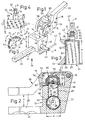
- a grinder or grinder 10 for crushing - not for the sake of clarity in the drawing reproduced - has surgical bone parts a housing-like base part or mill base 12, for example cuboid shape one on a hinge tongue 14 of the Mill base 12 by at least one axle pin 16 hinged cover part or mill cover 18, the / the supplemented the mill base 12 to form a housing.
- the grip profile 20 of the mill base 12 is circulating for better handling Handle throats 21 equipped.
- the mill base 12 penetrates - across the handle profiles 20 - a tubular channel 22 of diameter d, for example 30 mm, which receives a grinding drum 24. Latter is open on one end and the resulting the drum axis A crossing mouth 25 of a ring-like Radial collar 26 surrounded. This is in the installed position the grinding drum 24 in a shoulder-like ring heel 23, the - comprising the channel 22 - in a side surface 13 of the grinding base 12 is molded. Is other the grinding drum 24 with the axial length e of about 60 mm an end plate 28 closed, one of which is axial Bearing pin 30 protrudes. In the bearing pin 30 is - under Formation of an end plate 31 - a circumferential groove 32 is formed; four flats 34 close to the drum of the bearing pin 30, which i. w. create a square.
- the grinding drum 24 When assembling the mill 10, the grinding drum 24 in inserted that channel 22 and their bearing pin 30 through one serving as a bearing recess central hole 36 one Channel 22 - as part of the other side surface 13 - one end covering mold plate 38 pushed until the Front plate 28 of this form plate 38 on the inside and the Radial collar 26 the shoulder-like paragraph described 23 concerns. Then the bearing pin 30 is from the outside a grip sleeve 40 of a twist grip 42 is attached to that square-like area of the bearing pin 30 in one corresponding recess 41 of the grip sleeve 40 is seated. Then 3, the rotary handle 42 according to FIG Circumferential groove 32 protruding radial screw 43 on bearing pin 30 set so that when turning the handle 42 over a spoke rod 44 penetrating it diametrically Grinding drum 24 is rotated.
- a lever 45 running parallel to the spoke rod 44 is hinged in one end in a slot-like recess 46 and carries a detent ball 47 at the other end; this sits in the use position of the rotary handle 42 a in the circumferential groove 32 of the bearing pin 30th
- the grinding drum rotates 24 in the mill base 12 on a molded in this - rectangular cross section - feed chute 48 of Width k (k ⁇ d).
- the grinding drum 24 forms an in Direction of rotation z curved - sieve-like - bottom for the Feed chute 48; in the cylindrical drum shell 50 the Grinding drum 24 is provided with a pattern of openings 52.
- the mill cover 18 rests in its closed position lateral support edges 17 of a lid head 19 End faces 15 of the mill base 12 and sets its body continued.
- the mill cover 18 has an indentation 54 provided which in the closed position of the mill 10 - Fig. 2nd - Above the end face 15 of the mill base 12 is.
- This indentation 54 takes a bearing body 56 for one that can be lowered into the feed shaft 48 and has a cross-section filling pressure body 58; whose the Mill drum 24 assigned partially cylindrical curved Pressure area 60 is the outer diameter d of the drum shell 50 adjusted.
- the pressure body 58 offers shoulder-like shoulders on both sides 64 on; the pressure body 58 is approximately "T" -shaped with a crosshead delimited by that pressure surface 60 59 and a stamp-like flanked by paragraphs 64 Sliding section 66 which protrudes into that guide space 62.
- Parallel to axis B is that of the mill base 12 with the mill cover 18 connecting pin 16 protrude from the bearing body 56 bolts 74 on both sides in each Elongated hole 76 of the flank walls delimiting the indentation 54 78 of the lid head 19.
- the roof plate 79 ends at a distance from the axle hole 80 in FIG Flank wall 78 with an edge inclined to the indentation 54 82. Between this and that axle hole 80 one places the Cross section of the recess 54 shortening molding 84 of the Flank wall 78 on. Form these bilateral projections 84 - - Stop edges running parallel to pivot pin 77 86 for the pivotable about the axis Q of the screw pins 74 Bearing body 56.
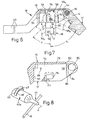
- 6 - on both sides of the vertical position here in the closed position of the mill 10 - each shows an end position of the pressure body 58 when the bearing body 56 is pivoted. 6, a swivel angle q of approximately 45 ° for the bearing body 56 a shown in broken lines or the pressure body 58 a can be seen when the latter strikes a wall surface 55 of the indentation 54.
- the other end position 58 b of the pressure body 58, indicated by dashed lines, is - as described - determined by the stop edges 86 of the projections 84 with a swivel angle q 1 of approximately 70 ° here.
- the mill 10 is primarily used to produce bone meal for surgical procedures.
- the bone particles are at open mill 10 according to FIG. 1 in the insertion direction x in the feed shaft 48 is applied to the drum shell 52.
- the pendulum pressure body arrives 58 into the feed chute 48 and begins the bone particles to press against the drum shell 52.
- the energy store (s) 72 becomes the pressure of the printing surface 60 - with constant pressure by the user on the Handle profiles 20 - depending on the thickness of the particle layer regulated; so the user can be independent of the thickness of the particle layer, the mill 10 always with apply constant force.
- stop or brake pins 88 are for setting the exact Swivel radius of the pressure body 58 or its introduction in the feed shaft 48 necessary.
- the surfaces of the feed shaft 48, the pressure body 60 and of the tubular channel 22 are with stainless surgical Steel lined to contaminate the bone material with abrasion of die-cast from an aluminum alloy Hold the mill base 12 down.
- This disguise can be a coating or one in the feed chute 48 or the steel pipe 22 inserted and fixed there be that in the drawing for reasons of clarity is not shown.
Landscapes
- Health & Medical Sciences (AREA)
- Engineering & Computer Science (AREA)
- Transplantation (AREA)
- Food Science & Technology (AREA)
- Orthopedic Medicine & Surgery (AREA)
- Vascular Medicine (AREA)
- Public Health (AREA)
- Oral & Maxillofacial Surgery (AREA)
- Biomedical Technology (AREA)
- Heart & Thoracic Surgery (AREA)
- Physical Education & Sports Medicine (AREA)
- Life Sciences & Earth Sciences (AREA)
- Animal Behavior & Ethology (AREA)
- General Health & Medical Sciences (AREA)
- Cardiology (AREA)
- Veterinary Medicine (AREA)
- Disintegrating Or Milling (AREA)
- Crushing And Grinding (AREA)
- Surgical Instruments (AREA)
- Polishing Bodies And Polishing Tools (AREA)
- Finish Polishing, Edge Sharpening, And Grinding By Specific Grinding Devices (AREA)
- Crushing And Pulverization Processes (AREA)
Description
- Fig. 1:
- eine Schrägsicht auf eine erfindungsgemäße Mahlvorrichtung in geöffnetem Zustand mit seitlich abragendem Drehgriff;
- Fig. 2:
- eine teilweise geschnittene Seitenansicht der Mahlvorrichtung in geschlossener Mahlstellung;
- Fig. 3:
- eine gegenüber Fig. 1 vergrößerte und teilweise geschnittene Mahltrommel als Detail der Mahlvorrichtung;
- Fig. 4:
- einen Teil der Mahltrommel in Draufsicht;
- Fig. 5:
- einen Teilquerschnitt durch Fig. 4 nach deren Linie V - V;
- Fig. 6:
- einen Teil der Fig. 2 in einer gegenüber dieser anderen Anordnung;
- Fig. 7:
- einen vergrößerten Abschnitt eines Details der Fig. 6;
- Fig. 8:
- eine weitere Ausgestaltung des Drehgriffes.
Claims (17)
- Vorrichtung zum mahlenden Zerkleinern von granulatähnlichem Haufwerk, insbesondere von Knochenpartikeln, mit in einem kanalartigen Raum (22) eines Gehäuses (12, 18) gelagerter Mahltrommel (24), die einen siebartig perforierten Trommelmantel (50) aufweist sowie durch eine außerhalb des Gehäuses (12, 18) angeordnete Dreheinrichtung (42) um ihre Trommelachse (A) bewegbar ist, wobei der Trommelmantel (50) den Boden eines im Gehäuse vorgesehenen Zuführschachtes (48) bildet und in letzterem ein mit einer in Gebrauchsstellung dem Trommelmantel (50) gegenüberstehenden Druckfläche (60) ausgestatteter sowie an seinem von der Druckfläche (60) fernen Ende von zumindest einem Kraftspeicher (72) beaufschlagbarer beweglicher Druckkörper (58) angeordnet ist, dessen quer zur Trommelachse (A) verlaufende Breite geringer ist als-der Durchmesser (d) des Trommelmantels (50),
dadurch gekennzeichnet, dass der in einem an einem den Zuführschacht (48) enthaltenden Sockelteil (12) des Gehäuses (12, 18) um eine Achse (B) schwenkbar gelagerten Deckelteil (18) des Gehäuses (12, 18) gleitbare Druckkörper (58) an jenem von der Druckfläche (60) fernen Ende von einer Feder als Kraftspeicher (72) beaufschlagt ist. - Vorrichtung nach Anspruch 1, dadurch gekennzeichnet, dass der Druckkörper (58) am Deckelteil (18) schwenkbar (Winkel q, q1) gelagert ist.
- Vorrichtung mit querschnittlich entsprechend der Kontur des zylindrischen Trommelmantels (50) gekrümmter Druckfläche (60) nach Anspruch 1 oder 2, dadurch gekennzeichnet, dass der Querschnitt eines die. Druckfläche (60) enthaltenden und im Zuführschacht (48) geführten Querhauptes (59) des Druckkörpers (58) den Schachtquerschnitt mit Spiel ausfüllt.
- Vorrichtung nach einem der Ansprüche 1 bis 3, dadurch gekennzeichnet, dass das dem Kraftspeicher (72) zugekehrte Ende des Druckkörpers (58) in einem Lagerkörper (56) vorgesehen und dieser mit Spiel schwenkbar in einer Einformung (54) des Deckelteils (18) angebracht ist.
- Vorrichtung nach Anspruch 3 oder 4, dadurch gekennzeichnet, dass der Druckkörper (58) aus jenem Querhaupt (59) und einem an dieses unter Bildung schulterartiger Absätze (64) angeformten Gleitabschnitt (66) besteht, welcher in einen Führungsraum. (62) des Lagerkörpers (56) eingreift.
- Vorrichtung nach Anspruch 4 oder 5, dadurch gekennzeichnet, dass der Lagerkörper (56) um eine quer zur Hubrichtung des Druckkörpers (58) verlaufende Achse (Q) schwenkbar ist und diese beidseits des Lagerkörpers (56) in jeweils einem parallel zu Auflagekanten (17) des Deckelteils (18) in dessen Flankenwänden (78) verlaufenden Langloch (76) lagert.
- Vorrichtung nach Anspruch 6, dadurch gekennzeichnet, dass die Länge (f) des Langloches (76) durch wenigstens ein stiftartiges Element (77) veränderbar ist.
- Vorrichtung nach einem der Ansprüche 4 bis 7, dadurch gekennzeichnet, dass Begrenzungsflächen (55, 86) der Einformung (54) des Deckelteils (18) den Schwenkbereich des Druckkörpers (58) bestimmen.
- Vorrichtung nach einem der Ansprüche 4 bis 8, dadurch gekennzeichnet, dass in wenigstens einer Flankenwand (78) zur Begrenzung der schwenkbahn des Lagerkörpers (56) ein Anschlagstift (88) vorgesehen ist.
- Vorrichtung nach einem der Ansprüche 4 bis 9, dadurch gekennzeichnet, dass das dem Kraftspeicher (72) zugekehrte Ende des Druckkörpers (58) im Führungsraum (62) des Lagerkörpers (56) durch Kulissenelemente (68, 70) gegen den Kraftspeicher (72) anhebbar geführt ist.
- Vorrichtung mit von einer ihrer Stirnseiten abragendem axialem Lagerstift (30) im Gehäuse (12) gelagerter Mahltrommel (24) nach einem der Ansprüche 1 bis 10, dadurch gekennzeichnet, dass die andernends offene Mahltrommel (24) mit einem ihre Mündung (25) umgebenden Radialkragen (26) in einem schulterartigen Ringabsatz (23) des Sockelteils (12) gelagert ist.
- Vorrichtung nach Anspruch 11, dadurch gekennzeichnet, dass der Lagerstift (30) außerhalb des Sockelteils (12) eine Umfangsnut (32) als Führungselement für einen Drehgriff (42) als Dreheinrichtung aufweist.
- Vorrichtung nach Anspruch 11 oder 12, dadurch gekennzeichnet, dass der Lagerstift (30) polygonen Querschnittes undrehbar in einer entsprechenden Ausnehmung (41) einer Griffhülse (40) des Drehgriffes (42) ruht, wobei in die Umfangsnut (32) radial ein Halteelement (43, 47) des Drehgriffes (42) eingreift, das an der Griffhülse (40) des Drehgriffes (42) als das freie Ende eines die Griffhülse (40) teilweise durchsetzenden Klapphebels (45) ausgebildet ist.
- Vorrichtung nach wenigstens einem der Ansprüche 1 bis 13, dadurch gekennzeichnet, dass die Lagen der Durchbrüche oder Bohrungen (52) im siebartigen Trommelmantel (50) durch Knotenstellen -eines Konstruktionsnetzes bestimmt sind, das durch von Radialebenen am Trommelmantel (50) erzeugten Konstruktionslinien (E) und diese im einem Winkel (w) schneidenden weiteren Konstruktionslinien (F) auf den Trommelmantel (50) gebildet ist, wobei dieser Winkel (w) bevorzugt etwa 50° bis 70°, insbesondere etwa 60°, mißt.
- Vorrichtung nach Anspruch 14, dadurch gekennzeichnet, dass die Durchbrüche oder Bohrungen (52) den Trommelmantel (50) der Dicke (y) in einem Neigungwinkel (t) zu Durchmessergeraden (D) der Mahltrommel (24) durchsetzen, wobei der Neigungswinkel bevorzugt zwischen 40° und 50°, insbesondere etwa 45°, misst.
- Vorrichtung nach wenigstens einem der Ansprüche 1 bis 15, dadurch gekennzeichnet, dass die vom Mahlgut berührbaren Flächen (22, 48, 60) aus rostfreiem Stahl bestehen oder mit diesem beschichtet sind.
- Vorrichtung nach wenigstens einem der Ansprüche 1 bis 16, dadurch gekennzeichnet, dass sowohl vom Sockelteil (12) als auch vom Deckelteil (18) des Gehäuses (12, 18) jeweils ein Griffprofil (20) abragt und beide Griffprofile (20) in geschlossenem Zustand der Vorrichtung (10) ein parallel verlaufendes Griffpaar bilden.
Applications Claiming Priority (3)
| Application Number | Priority Date | Filing Date | Title |
|---|---|---|---|
| DE29719385U | 1997-10-31 | ||
| DE29719385U DE29719385U1 (de) | 1997-10-31 | 1997-10-31 | Vorrichtung zum mahlenden Zerkleinern von granulatähnlichem Haufwerk |
| PCT/EP1998/002874 WO1999022676A1 (de) | 1997-10-31 | 1998-05-15 | Vorrichtung zum mahlenden zerkleinern von granulatähnlichem haufwerk |
Publications (2)
| Publication Number | Publication Date |
|---|---|
| EP1027019A1 EP1027019A1 (de) | 2000-08-16 |
| EP1027019B1 true EP1027019B1 (de) | 2003-10-08 |
Family
ID=8048018
Family Applications (1)
| Application Number | Title | Priority Date | Filing Date |
|---|---|---|---|
| EP98929323A Expired - Lifetime EP1027019B1 (de) | 1997-10-31 | 1998-05-15 | Vorrichtung zum mahlenden zerkleinern von granulatähnlichem haufwerk |
Country Status (5)
| Country | Link |
|---|---|
| EP (1) | EP1027019B1 (de) |
| AT (1) | ATE251430T1 (de) |
| AU (1) | AU7912898A (de) |
| DE (2) | DE29719385U1 (de) |
| WO (1) | WO1999022676A1 (de) |
Families Citing this family (2)
| Publication number | Priority date | Publication date | Assignee | Title |
|---|---|---|---|---|
| DE29719385U1 (de) * | 1997-10-31 | 1998-02-12 | MONDEAL Medical Systems GmbH, 78532 Tuttlingen | Vorrichtung zum mahlenden Zerkleinern von granulatähnlichem Haufwerk |
| EP3378445A1 (de) * | 2017-03-23 | 2018-09-26 | Ronvig Dental Mfg. A/S | Knochenschleifer |
Family Cites Families (8)
| Publication number | Priority date | Publication date | Assignee | Title |
|---|---|---|---|---|
| US4706897A (en) * | 1986-10-29 | 1987-11-17 | Biodynamic Technologies Inc. | Apparatus for comminuting bone |
| DE3734714C1 (en) * | 1987-10-14 | 1988-12-08 | Leibinger Oswald Gmbh | Device for the preparation of comminuted bone grafts |
| DE3808409A1 (de) * | 1988-03-14 | 1989-09-28 | Werner Weinmueller | Knochenmuehle |
| FR2679793B1 (fr) * | 1991-08-02 | 1993-10-29 | Boutmy Ets | Dispositif de parcellisation de tissus osseux spongieux, en vue de leur compactage pour leur reimplantation. |
| FR2712483B1 (fr) * | 1993-11-19 | 1998-08-28 | Louis Setiey | Dispositif pour la réalisation de copeaux d'os, à utilisation en chirurgie orthopédique. |
| SE503270C2 (sv) * | 1994-08-22 | 1996-04-29 | Harry Wexell | Kvarn, förfarande för tillverkning av bentransplantationsmaterial och användning av kvarn för sådan tillverkning |
| DE19644015C1 (de) * | 1996-10-31 | 1998-01-02 | Roswitha Quetin | Knochenraspel |
| DE29719385U1 (de) * | 1997-10-31 | 1998-02-12 | MONDEAL Medical Systems GmbH, 78532 Tuttlingen | Vorrichtung zum mahlenden Zerkleinern von granulatähnlichem Haufwerk |
-
1997
- 1997-10-31 DE DE29719385U patent/DE29719385U1/de not_active Expired - Lifetime
-
1998
- 1998-05-15 AT AT98929323T patent/ATE251430T1/de not_active IP Right Cessation
- 1998-05-15 WO PCT/EP1998/002874 patent/WO1999022676A1/de not_active Ceased
- 1998-05-15 EP EP98929323A patent/EP1027019B1/de not_active Expired - Lifetime
- 1998-05-15 DE DE59809877T patent/DE59809877D1/de not_active Expired - Fee Related
- 1998-05-15 AU AU79128/98A patent/AU7912898A/en not_active Abandoned
Also Published As
| Publication number | Publication date |
|---|---|
| ATE251430T1 (de) | 2003-10-15 |
| DE59809877D1 (de) | 2003-11-13 |
| WO1999022676A1 (de) | 1999-05-14 |
| DE29719385U1 (de) | 1998-02-12 |
| EP1027019A1 (de) | 2000-08-16 |
| AU7912898A (en) | 1999-05-24 |
Similar Documents
| Publication | Publication Date | Title |
|---|---|---|
| DE69519862T2 (de) | Mühle, verfahren für die herstellung von knochentransplantationsmaterial und verwendung einer mühle für solch eine herstellung | |
| DE19509317A1 (de) | Implantat zum Einsetzen zwischen Wirbelkörper der Wirbelsäule als Platzhalter | |
| WO2007039613A1 (de) | Dosiereinrichtung für pulver- oder pastenförmige substanzen | |
| WO1993020901A1 (de) | Behälter mit druckgefäss zum regenerieren und lagern von tennisbällen | |
| EP1313392B1 (de) | Küchenreibe | |
| DE3119605A1 (de) | Raeumvorrichtung | |
| EP1931952A1 (de) | Dosiereinrichtung für pulver- oder pastenförmige substanzen | |
| EP1862715B1 (de) | Pressvorrichtung | |
| DE3333459A1 (de) | Fliehkraftbearbeitungsmaschine | |
| EP3275639A1 (de) | Stempel für eine rundläuferpresse | |
| EP1027019A1 (de) | Vorrichtung zum mahlenden zerkleinern von granulatähnlichem haufwerk | |
| WO2011054334A1 (de) | Fräswalze | |
| DE19903526B4 (de) | Separationseinrichtung für aus unterschiedlichen Stoffen zusammengesetzte Produkte | |
| DE202014004257U1 (de) | Rollenpresse zur Hochdruckbehandlung körnigen Mahlguts | |
| DE3626365A1 (de) | Vorrichtung sowie verfahren zur herstellung von mit einem seitlichen fortsatz versehenen tiefenzylindrischen oder kegeligen formkoerpern, insbesondere henkeltassen | |
| EP0690774B1 (de) | Presswerkzeug zum isostatischen pressen steilwandiger topfförmiger gegenstände aus keramischem granulat | |
| EP4279257B1 (de) | Tablettierwerkzeug | |
| DE202005012516U1 (de) | Kosmetikbehälter mit integriertem Mischereinsatz | |
| DE4037592A1 (de) | Werkzeuggriff fuer werkzeuge, insbesondere schraubendreher | |
| DE102019005890A1 (de) | Prallmühle zur Zerkleinerung von Feststoffen | |
| DE4216863A1 (de) | Verfahren zum Zerkleinern, vorzugsweise von Altreifen und Vorrichtung hierfür | |
| DE918896C (de) | Spritzgussmaschine zum Formen plastischer organischer Kunststoffe | |
| DE1627950C3 (de) | Vorrichtung zum Pressen von trockenem Gut oder Gemischen aus trockenen und feuchten Bestandteilen, insbesondere Trockengrünfutter in Stangen | |
| DE29801312U1 (de) | Werkzeuganordnung zur Herstellung von ringförmigen Preßlingen mit Hilfe einer Rundläuferpresse | |
| DE19801218A1 (de) | Knochenmühle |
Legal Events
| Date | Code | Title | Description |
|---|---|---|---|
| PUAI | Public reference made under article 153(3) epc to a published international application that has entered the european phase |
Free format text: ORIGINAL CODE: 0009012 |
|
| 17P | Request for examination filed |
Effective date: 20000418 |
|
| AK | Designated contracting states |
Kind code of ref document: A1 Designated state(s): AT BE CH DE DK ES FR GB GR IE IT LI NL PT SE |
|
| GRAH | Despatch of communication of intention to grant a patent |
Free format text: ORIGINAL CODE: EPIDOS IGRA |
|
| GRAS | Grant fee paid |
Free format text: ORIGINAL CODE: EPIDOSNIGR3 |
|
| GRAA | (expected) grant |
Free format text: ORIGINAL CODE: 0009210 |
|
| AK | Designated contracting states |
Kind code of ref document: B1 Designated state(s): AT BE CH DE DK ES FR GB GR IE IT LI NL PT SE |
|
| PG25 | Lapsed in a contracting state [announced via postgrant information from national office to epo] |
Ref country code: NL Free format text: LAPSE BECAUSE OF FAILURE TO SUBMIT A TRANSLATION OF THE DESCRIPTION OR TO PAY THE FEE WITHIN THE PRESCRIBED TIME-LIMIT Effective date: 20031008 Ref country code: IT Free format text: LAPSE BECAUSE OF FAILURE TO SUBMIT A TRANSLATION OF THE DESCRIPTION OR TO PAY THE FEE WITHIN THE PRESCRIBED TIME-LIMIT;WARNING: LAPSES OF ITALIAN PATENTS WITH EFFECTIVE DATE BEFORE 2007 MAY HAVE OCCURRED AT ANY TIME BEFORE 2007. THE CORRECT EFFECTIVE DATE MAY BE DIFFERENT FROM THE ONE RECORDED. Effective date: 20031008 Ref country code: IE Free format text: LAPSE BECAUSE OF FAILURE TO SUBMIT A TRANSLATION OF THE DESCRIPTION OR TO PAY THE FEE WITHIN THE PRESCRIBED TIME-LIMIT Effective date: 20031008 Ref country code: GB Free format text: LAPSE BECAUSE OF FAILURE TO SUBMIT A TRANSLATION OF THE DESCRIPTION OR TO PAY THE FEE WITHIN THE PRESCRIBED TIME-LIMIT Effective date: 20031008 Ref country code: FR Free format text: LAPSE BECAUSE OF FAILURE TO SUBMIT A TRANSLATION OF THE DESCRIPTION OR TO PAY THE FEE WITHIN THE PRESCRIBED TIME-LIMIT Effective date: 20031008 |
|
| REG | Reference to a national code |
Ref country code: GB Ref legal event code: FG4D Free format text: NOT ENGLISH |
|
| REG | Reference to a national code |
Ref country code: CH Ref legal event code: EP |
|
| REG | Reference to a national code |
Ref country code: IE Ref legal event code: FG4D Free format text: GERMAN |
|
| REF | Corresponds to: |
Ref document number: 59809877 Country of ref document: DE Date of ref document: 20031113 Kind code of ref document: P |
|
| PG25 | Lapsed in a contracting state [announced via postgrant information from national office to epo] |
Ref country code: SE Free format text: LAPSE BECAUSE OF FAILURE TO SUBMIT A TRANSLATION OF THE DESCRIPTION OR TO PAY THE FEE WITHIN THE PRESCRIBED TIME-LIMIT Effective date: 20040108 Ref country code: GR Free format text: LAPSE BECAUSE OF FAILURE TO SUBMIT A TRANSLATION OF THE DESCRIPTION OR TO PAY THE FEE WITHIN THE PRESCRIBED TIME-LIMIT Effective date: 20040108 Ref country code: DK Free format text: LAPSE BECAUSE OF FAILURE TO SUBMIT A TRANSLATION OF THE DESCRIPTION OR TO PAY THE FEE WITHIN THE PRESCRIBED TIME-LIMIT Effective date: 20040108 |
|
| PG25 | Lapsed in a contracting state [announced via postgrant information from national office to epo] |
Ref country code: ES Free format text: LAPSE BECAUSE OF FAILURE TO SUBMIT A TRANSLATION OF THE DESCRIPTION OR TO PAY THE FEE WITHIN THE PRESCRIBED TIME-LIMIT Effective date: 20040119 |
|
| REG | Reference to a national code |
Ref country code: CH Ref legal event code: NV Representative=s name: HIEBSCH & PEEGE AG PATENTANWAELTE |
|
| NLV1 | Nl: lapsed or annulled due to failure to fulfill the requirements of art. 29p and 29m of the patents act | ||
| GBV | Gb: ep patent (uk) treated as always having been void in accordance with gb section 77(7)/1977 [no translation filed] |
Effective date: 20031008 |
|
| PG25 | Lapsed in a contracting state [announced via postgrant information from national office to epo] |
Ref country code: BE Free format text: LAPSE BECAUSE OF NON-PAYMENT OF DUE FEES Effective date: 20040531 |
|
| REG | Reference to a national code |
Ref country code: IE Ref legal event code: FD4D |
|
| PLBE | No opposition filed within time limit |
Free format text: ORIGINAL CODE: 0009261 |
|
| STAA | Information on the status of an ep patent application or granted ep patent |
Free format text: STATUS: NO OPPOSITION FILED WITHIN TIME LIMIT |
|
| 26N | No opposition filed |
Effective date: 20040709 |
|
| EN | Fr: translation not filed | ||
| BERE | Be: lapsed |
Owner name: *MONDEAL MEDICAL SYSTEMS G.M.B.H. Effective date: 20040531 |
|
| PG25 | Lapsed in a contracting state [announced via postgrant information from national office to epo] |
Ref country code: PT Free format text: LAPSE BECAUSE OF NON-PAYMENT OF DUE FEES Effective date: 20040308 |
|
| REG | Reference to a national code |
Ref country code: CH Ref legal event code: PFA Owner name: MONDEAL MEDICAL SYSTEMS GMBH Free format text: MONDEAL MEDICAL SYSTEMS GMBH#MOLTKESTRASSE 41,#78532 TUTTLINGEN (DE) -TRANSFER TO- MONDEAL MEDICAL SYSTEMS GMBH#MOLTKESTRASSE 41,#78532 TUTTLINGEN (DE) |
|
| PGFP | Annual fee paid to national office [announced via postgrant information from national office to epo] |
Ref country code: CH Payment date: 20080526 Year of fee payment: 11 |
|
| PGFP | Annual fee paid to national office [announced via postgrant information from national office to epo] |
Ref country code: AT Payment date: 20080521 Year of fee payment: 11 |
|
| PGFP | Annual fee paid to national office [announced via postgrant information from national office to epo] |
Ref country code: DE Payment date: 20080722 Year of fee payment: 11 |
|
| REG | Reference to a national code |
Ref country code: CH Ref legal event code: PL |
|
| PG25 | Lapsed in a contracting state [announced via postgrant information from national office to epo] |
Ref country code: LI Free format text: LAPSE BECAUSE OF NON-PAYMENT OF DUE FEES Effective date: 20090531 Ref country code: CH Free format text: LAPSE BECAUSE OF NON-PAYMENT OF DUE FEES Effective date: 20090531 Ref country code: AT Free format text: LAPSE BECAUSE OF NON-PAYMENT OF DUE FEES Effective date: 20090515 |
|
| PG25 | Lapsed in a contracting state [announced via postgrant information from national office to epo] |
Ref country code: DE Free format text: LAPSE BECAUSE OF NON-PAYMENT OF DUE FEES Effective date: 20091201 |