EP1027092B1 - Gerät zum auftragen von flüssigkeiten auf die haut - Google Patents
Gerät zum auftragen von flüssigkeiten auf die haut Download PDFInfo
- Publication number
- EP1027092B1 EP1027092B1 EP98952817A EP98952817A EP1027092B1 EP 1027092 B1 EP1027092 B1 EP 1027092B1 EP 98952817 A EP98952817 A EP 98952817A EP 98952817 A EP98952817 A EP 98952817A EP 1027092 B1 EP1027092 B1 EP 1027092B1
- Authority
- EP
- European Patent Office
- Prior art keywords
- cartridge
- applicator
- liquid
- applicator according
- connecting means
- Prior art date
- Legal status (The legal status is an assumption and is not a legal conclusion. Google has not performed a legal analysis and makes no representation as to the accuracy of the status listed.)
- Expired - Lifetime
Links
- 239000007788 liquid Substances 0.000 title claims abstract description 46
- 239000012263 liquid product Substances 0.000 claims description 4
- 210000000078 claw Anatomy 0.000 claims description 3
- 230000000295 complement effect Effects 0.000 claims description 3
- 230000007423 decrease Effects 0.000 claims description 2
- 230000001681 protective effect Effects 0.000 claims description 2
- 238000003892 spreading Methods 0.000 claims description 2
- 230000001225 therapeutic effect Effects 0.000 claims 2
- 230000000903 blocking effect Effects 0.000 claims 1
- 239000000645 desinfectant Substances 0.000 abstract description 3
- 239000012530 fluid Substances 0.000 abstract description 2
- 238000004806 packaging method and process Methods 0.000 description 7
- 239000000463 material Substances 0.000 description 5
- 238000003860 storage Methods 0.000 description 5
- 230000002093 peripheral effect Effects 0.000 description 4
- 239000000047 product Substances 0.000 description 4
- 238000004500 asepsis Methods 0.000 description 3
- 230000003247 decreasing effect Effects 0.000 description 3
- 208000027418 Wounds and injury Diseases 0.000 description 2
- 239000008186 active pharmaceutical agent Substances 0.000 description 2
- 238000002788 crimping Methods 0.000 description 2
- 229940088679 drug related substance Drugs 0.000 description 2
- 229920003023 plastic Polymers 0.000 description 2
- -1 polypropylene Polymers 0.000 description 2
- 238000003466 welding Methods 0.000 description 2
- 239000004698 Polyethylene Substances 0.000 description 1
- 239000004743 Polypropylene Substances 0.000 description 1
- 239000013543 active substance Substances 0.000 description 1
- 239000011324 bead Substances 0.000 description 1
- 238000005452 bending Methods 0.000 description 1
- 230000001680 brushing effect Effects 0.000 description 1
- 230000005465 channeling Effects 0.000 description 1
- 238000004891 communication Methods 0.000 description 1
- 230000006378 damage Effects 0.000 description 1
- 238000009826 distribution Methods 0.000 description 1
- 238000001035 drying Methods 0.000 description 1
- 229940082150 encore Drugs 0.000 description 1
- 239000006260 foam Substances 0.000 description 1
- 239000011796 hollow space material Substances 0.000 description 1
- 208000014674 injury Diseases 0.000 description 1
- 238000003780 insertion Methods 0.000 description 1
- 230000037431 insertion Effects 0.000 description 1
- 238000012423 maintenance Methods 0.000 description 1
- 239000002991 molded plastic Substances 0.000 description 1
- 238000012856 packing Methods 0.000 description 1
- 239000004033 plastic Substances 0.000 description 1
- 229920000573 polyethylene Polymers 0.000 description 1
- 229920000642 polymer Polymers 0.000 description 1
- 229920001155 polypropylene Polymers 0.000 description 1
- 230000000750 progressive effect Effects 0.000 description 1
- 230000000717 retained effect Effects 0.000 description 1
Images


Classifications
-
- B—PERFORMING OPERATIONS; TRANSPORTING
- B65—CONVEYING; PACKING; STORING; HANDLING THIN OR FILAMENTARY MATERIAL
- B65D—CONTAINERS FOR STORAGE OR TRANSPORT OF ARTICLES OR MATERIALS, e.g. BAGS, BARRELS, BOTTLES, BOXES, CANS, CARTONS, CRATES, DRUMS, JARS, TANKS, HOPPERS, FORWARDING CONTAINERS; ACCESSORIES, CLOSURES, OR FITTINGS THEREFOR; PACKAGING ELEMENTS; PACKAGES
- B65D47/00—Closures with filling and discharging, or with discharging, devices
- B65D47/42—Closures with filling and discharging, or with discharging, devices with pads or like contents-applying means
-
- A—HUMAN NECESSITIES
- A61—MEDICAL OR VETERINARY SCIENCE; HYGIENE
- A61M—DEVICES FOR INTRODUCING MEDIA INTO, OR ONTO, THE BODY; DEVICES FOR TRANSDUCING BODY MEDIA OR FOR TAKING MEDIA FROM THE BODY; DEVICES FOR PRODUCING OR ENDING SLEEP OR STUPOR
- A61M35/00—Devices for applying media, e.g. remedies, on the human body
- A61M35/003—Portable hand-held applicators having means for dispensing or spreading integral media
- A61M35/006—Portable hand-held applicators having means for dispensing or spreading integral media using sponges, foams, absorbent pads or swabs as spreading means
Definitions
- the present invention relates to a skin liquid applicator, type comprising a hydrophilic pad for applying the liquid to an area to be treated and means for connecting the buffer to a storage cartridge liquid, which connecting means are suitable for mounting the buffer next to a liquid flow outlet from the cartridge.
- hydrophilic pad it is common to use a hydrophilic pad to apply to a injury a disinfectant liquid or a drug substance.
- hydrophilic buffer To avoid too rapid drying of the hydrophilic buffer, during its storage, it is known to store the hydrophilic buffer separately and the liquid intended to impregnate the tampon.
- the document FR-A-2,732,585 describes for example a package comprising two initially separate compartments in which are arranged on the one hand a hydrophilic buffer and on the other hand a liquid active product. Before using the tampon, the two compartments are put in communication, so that the active liquid product soaks the buffer.
- the object of the invention is to propose a suitable skin applicator to receive a liquid active product packaged separately, not requiring not obtaining specific certificates for the applicator associated with the independently certified liquid storage container, allowing convenient application of the liquid to a wound.
- the invention relates to a skin liquid applicator of the aforementioned type, characterized in that the tampon comprises a hydrophilic strip folded back on itself and the connecting means include means for holding the flow outlet of the cartridge embedded between the two folded edges of the strip.
- the invention also relates to a care kit, characterized in that it comprises at least one hermetically sealed cartridge containing an aseptic treatment liquid and at least one applicator such as defined above, an applicator being adapted to be mounted on a cartridge, which cartridge is initially separated from the applicator.
- the invention further relates to a care device, characterized in what it includes an applicator as defined above and a cartridge sealed containing an aseptic treatment liquid on which is mounted the applicator.
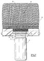
- FIGs 1 and 2 there is shown a skin applicator 10 mounted on a cartridge 12 for storing an aseptic liquid active product such than a disinfectant or drug substance.
- the cartridge is shown alone in Figure 3.
- Such cartridges are well known and are currently widely disseminated. They include, for example, a flexible body which is substantially cylindrical 14 made of molded plastic. The body is extended at its upper part by a plug 16 made integrally with the body.
- the body 14 In the vicinity of the plug 16, the body 14 generally comprises a peripheral groove 18 through which possibly extends a plastic web 20 produced during the assembly of the two half-shells forming the cartridge. Between the plug 16 and the groove 18, the cartridge has a progressively narrowed section forming a neck.
- the capacity of such cartridges is adapted to contain the necessary amount of liquid for single use. This capacity is between 1 ml and 5 ml and is for example equal to 2.5 ml, without these values are considered to be limiting.
- the applicator 10 shown in FIG. 1 essentially comprises a hydrophilic buffer 22 and means 24 for connecting the buffer 22 to the storage cartridge 12 opposite a liquid flow outlet out of it.
- Hydrophilic pad 22 has a hydrophilic strip 25, for example gauze.
- the connecting means 24 comprise two identical shaped blanks and joined. They are made of polymer, for example polypropylene or polyethylene. Once assembled, they form a necklace 26 of mounting on the cartridge, means 28 for holding the hydrophilic strip 25 and a hoop 30 for supporting this hydrophilic strip.
- Each blank has a half-collar 32 substantially in the form of semicircle and whose height is slightly less than the width of the throat 18.
- the half-collar is extended at each end by two sides coplanar 34 of rectangular shape.
- Each pan 34 is associated, in its lower part, to a flap 36 made of material and connected to the pan 34 by a fold line 38.
- the facing surfaces of the sides 34 and the flaps 36 are provided with pins 39 distributed according to conjugate patterns. They are suitable for maintaining the hydrophilic strip 25.
- the sides 34 on which are folded the flaps 36 form, as shown in the figure 4, band retaining claws 25.
- the two sides 34 are connected to each other by an arch 40 made of material, which has a general shape of U.
- This arch defines, with the half-collar 32, a rectangular hollow space 42. The latter has a size large enough to receive the neck of the cartridge and its cap 16.
- the thickness of the arch 40 decreases gradually from the sides 34 to the transverse end trigger guard connecting the two legs of the ark.
- the sides 34 comprise, preferably, added lateral projections 44 projecting from relative to the surface of the sides 34 and the arch 40 on the same side as the half-collar 32.
- one of the flaps 36 has on an external side wall a curved connecting lug 46 whose length substantially corresponds three times the thickness of the panels 34.
- the applicator is produced in the following manner.
- the two blanks are applied one on top of the other around the neck of a cartridge 12 sealed, so that the arches 40 and the sides 34 overlap two by two, the two half-collars 32 delimiting the collar 26 received in the groove 18 of the cartridge.
- the hydrophilic strip 25 is then folded back and on the other side of the arch 30 formed by the coupled arches 40.
- the length of the strip 25 is chosen so that the folded ends thereof come into contact with the pins 39 carried by the flaps 34, while remaining at distance from the fold lines 38.
- the hydrophilic strip 25 defines on either side of the arch 30 of the folded edges which form two areas application of the liquid product.
- the legs 46 are then folded down on either side of the two flanks joined together, so that the curved end of the legs 46 comes into support on the rear face of the flaps of the opposite blank.
- the flaps ensure retaining the hydrophilic strip, while the tabs 46 provide the securing the two blanks and holding the applicator on the cartridge.
- the applicator 10 is retained axially on the cartridge by the collar 26 engaged in the groove 18. However, the collar allows the rotation of the applicator around the axis of the cartridge.
- the two half-collars 32 connect to each other by a nip of width width gradually decreasing, able to receive the veil 20.
- the applicator is mounted on the cartridge in required aseptic conditions, as well as their packaging in a packaging such as a transparent plastic bag 50, shown in Figure 2.
- the aseptic conditions imposed for the bag 50 are less restrictive than those imposed for cartridge 12, since this sachet is not intended to directly contain an active substance.
- the pad thus being impregnated, the user can release it from its packing and brushing the area to be treated with the tampon, while not now that the cartridge body.
- the liquid product is applied by bringing the area to be treated into contact with one or other of the folded edges opposites of the strip which form the exposed areas of application of the liquid.
- the skin applicator can also be sold separately from the cartridge to which it must be associated for its use.
- the applicator is made as before, except for the first step in which the two blanks are joined without interposing a cartridge.
- the applicator thus formed can then be put in place later on a cartridge as shown in Figures 1 and 2.
- the projections 44 ensure, as shown in Figure 4, a spacing of the ends of the strip 25 in the region of the collar 26.
- the ends of the strip thus spaced from each other delimit a passage for introducing the plug 16 of a cartridge.
- the cartridge is introduced into the applicator by deformation elastic of the neck of the cartridge and the collar 26.
- the end plug 16 closing the fluid flow outlet is received after mounting in the rectangular space 42 delimited by the arch 30, as shown in FIGS. 1 and 2.
- the cartridge outlet is then encased between the two folded edges of the strip 25.
- the applicator can also be marketed in the form of a care kit comprising one or more applicators associated with a corresponding number of sealed cartridges, the cartridges being initially separate from applicators.
- the cartridges on which the applicator according to the invention is intended to be applied are widely marketed and have been obtained certificates guaranteeing their reliability and asepsis. Also, the use of these common cartridges associated with an applicator allows provide a care device that meets the necessary hygienic conditions to satisfactory use. In addition, this care device does not require request new certifications for its distribution.
- the arch 30 being of progressively decreasing thickness towards its far end of the cartridge, the pad is more flexible at its end intended to come into contact with the skin only at its fixing end on the cartridge, which facilitates application.
- the confinement of the ends of the hydrophilic strip between the sides 34 and the flaps 36 connected together by the fold lines 38 ensures channeling excess liquid into the hydrophilic strip, avoiding so that the liquid does not drip on the cartridge or the user's fingers.
- the blanks have a structure allowing a very good maintenance of the hydrophilic band.
- these can be from simpler structure and for example not having a flap.
- the band hydrophilic is then kept sandwiched directly between the sides 34, or attached directly to them.
- the blanks can be connected to each other by welding, riveting, crimping, or any other appropriate means to replace the implementation of tab 46.
- the two blanks can also have come material, especially in the upper area of the arch.
- the storage cartridge 12 comprises, in the region connecting the body 14 to the neck, a section cylindrical 50 provided externally with a thread 52 formed by a helical thread come of matter with the cartridge.
- Each half-collar 32 has internally on its section in semicircle shape a helical rib 54 forming a suitable thread to cooperate with the complementary thread 52 carried by the cartridge 12.
- the output of liquid flow out of the cartridge is initially closed by a plug 16 made integrally with the body, this plug 16 can be detached by shear.
- the applicator is engaged at the free end of the thread 52.
- the plug 16 is then placed in the arch 30 between the two folded edges of the hydrophilic strip 25.
- the user screws the applicator on the cartridge 12. This screwing causes the approximation axial of the applicator 10 and of the cartridge 12.
- the plug 16 held between the operator's fingers is sheared, causing opening the cartridge. So the liquid in it is free to flow to the hydrophilic strip 25.
- the cartridge, denoted 60 comprises a body 62 and a neck 64 externally provided with a thread 66.
- the neck 64 is closed by a perforable end face 68.
- the means 24 for connecting the hydrophilic strip 25 to the cartridge 62 are similar to those of the embodiment of Figure 7.
- a helical rib 52 is provided internally on each half-collar 32 to cooperate with the thread 66.
- the arch 30 carries a cross member 74 extending diametrically by compared to the cartridge 60.
- the cross member 74 is provided, in the middle, with a member perforation 76 oriented towards the perforable face 68 of the cartridge.
- the perforating member 76 extends along the axis of the thread 66.
- the perforating member 76 consists of a ribbed point, that is to say of an element of generally conical shape, following generatrices from which extend ribs converging at the top of the cone.
- the perforation member 76 urges the perforable face 68 and causes its perforation by progressive insertion of the member 76 with grooved surface.
- the skin applicator shown in FIG. 9 is adapted to be mounted on a cartridge 12 of the type shown in FIG. 3.
- the connecting means 24 comprise an elastic sleeve 80, around the axis of which the hydrophilic strip 25 is rotatably mounted by means of a ring 82 carrying the arch support 30.
- the sleeve 80 is made of an elastically deformable material. Internally it has a diameter slightly smaller than the diameter external of the body 14 of the cartridge. It has on its inner wall a peripheral bead 84 intended to be received in the groove 20 of the cartridge.
- the outer face of the sleeve 80 has a groove 86 in which the ring 82 is rotatably mounted around the axis common of the sleeve 80 and of the cartridge 14.
- the ring 82 formed in a rigid material. It carries the arch 30 along a diametrical plane.
- the elastic sleeve 80 is fitted to force around the body of the cartridge 14 until the peripheral bending 84 is received in the peripheral groove 80.
- the cap 16 of the cartridge is surrounded by the arch 30 and is disposed between the two folded edges of the hydrophilic strip 25.
- the operator angularly moves the strip hydrophilic 25 and the plug 16 relative to the body 14 of the cartridge.
- the cap 16 is sheared, thus releasing the liquid contained in the cartridge.
- the ranges of application liquid on the area to be treated are formed by the exposed faces of the folded edges of the hydrophilic strip 25.
- these areas have a large extent since they are formed by almost the entire exposed surface of the band.
- the application of liquid on a large area to be treated is therefore easy to produce, most of the surface of the hydrophilic strip can be used to apply the active liquid.
Landscapes
- Health & Medical Sciences (AREA)
- Engineering & Computer Science (AREA)
- Animal Behavior & Ethology (AREA)
- General Health & Medical Sciences (AREA)
- Biomedical Technology (AREA)
- Heart & Thoracic Surgery (AREA)
- Hematology (AREA)
- Life Sciences & Earth Sciences (AREA)
- Mechanical Engineering (AREA)
- Anesthesiology (AREA)
- Public Health (AREA)
- Veterinary Medicine (AREA)
- Absorbent Articles And Supports Therefor (AREA)
- Media Introduction/Drainage Providing Device (AREA)
- Coating Apparatus (AREA)
- Application Of Or Painting With Fluid Materials (AREA)
Claims (16)
- Geräte zum Auftragen von Flüssigkeiten auf die Haut, mit einem hydrophilen Tampon (22) zur Aufbringung der Flüssigkeit auf eine zu behandelnde Zone und Mitteln (24) zur Verbindung des Tampon (22) mit einer Kartusche (12) zur Aufnahme der Flüssigkeit, welche Verbindungsmittel (24) geeignet sind zur Montage des Tampon (22) in Bezug auf die Auslaßöffnung der Flüssigkeit an der Kartusche (12), wobei der Tampon (22) ein hydrophiles Band (25) umfaßt, und die Verbindungsmittel (24) Mittel (28) aufweisen, die die Auslaßöffnung der Kartusche eingefügt zwischen den beiden umgeschlagenen Rändern des Bandes (25) halten, dadurch gekennzeichnet, dass die Verbindungsmittel (24) so ausgebildet sind, dass sie eine relative Bewegung zwischen dem Gerät (10) und der Kartusche (12) zur Brechung eines Verschlußstopfes der Auslaßöffnung der Kartusche (12) gestatten.
- Gerät nach Anspruch 1, dadurch gekennzeichnet, dass die Verbindungsmittel einen Ring zur Befestigung am Hals einer Kartusche umfassen.
- Gerät nach Anspruch 2, dadurch gekennzeichnet. dass der Ring (26) zwei identische Bügel (32) umfaßt, die miteinander verbunden sind und jeweils einen Halbring bilden.
- Gerät nach Anspruch 3, dadurch gekennzeichnet, dass die beiden Bügel durch Schweißen, Nieten oder eine Verbindungsklammer verbunden sind, die einstückig mit einem Bügel hergestellt und über den anderen Bügel gelegt sind.
- Gerät nach einem der vorhergehenden Ansprüche, dadurch gekennzeichnet, dass die Verbindungsmittel (24) Mittel (44) zum Trennen der Ränder des hydrophilen Bandes (25) in der Verbindungszone mit der Kartusche aufweisen.
- Gerät nach Anspruch 2, dadurch gekennzeichnet, dass jeder Bügel beiderseits der Auslaßöffnung der Kartusche durch Klammern (28) zum Halten der Enden des hydrophilen Bandes (25) verlängert ist.
- Gerät nach einem der vorhergehenden Ansprüche, dadurch gekennzeichnet, dass der Tampon (22) eine flexible Stütze (30) umfaßt, an der ein hydrophiles Band (25) befestigt ist, und dass die flexible Stütze (30) mit den Verbindungsmitteln (24) verbunden ist.
- Gerät nach Anspruch 7, dadurch gekennzeichnet, dass die flexible Stütze (30) im wesentlichen die Form eines Bogens aufweist und einen Sitz (42) für die Aufnahme der Auslaßöffnung der Kartusche und gegebenenfalls eines Verschlußstopfes (16) der Kartusche bildet.
- Gerät nach Anspruch 7 oder 8, dadurch gekennzeichnet, dass die flexible Stütze (30) eine progressiv abnehmende Stärke von den Verbindungsmitteln (24) zu dem von den Verbindungsmitteln (24) entfernten Ende aufweist.
- Gerät nach einem der vorhergehenden Ansprüche, dadurch gekennzeichnet, dass es ein Perforationsorgan (76) für ein perforierbares Ende (68) der Kartusche (60) aufweist.
- Gerät nach einem der vorhergehenden Ansprüche, dadurch gekennzeichnet, dass die Verbindungsmittel (24) eine Gewinde (54) umfassen, das vorgesehen ist zum Zusammenwirken mit einem komplementären Gewinde (52,66) der Kartusche (12,60) zur Sicherung der Relativbewegung zwischen dem Gerät und der Kartusche.
- Gerät nach einem der Ansprüche 1 bis 10, dadurch gekennzeichnet, dass die Relativbewegung zwischen dem Gerät (10) und der Kartusche (12) eine Rotationsbewegung ist.
- Gerät nach einem der vorhergehenden Ansprüche, dadurch gekennzeichnet, dass das Gerät in einem Schutzbeutel angeordnet ist.
- Gerät nach einem der vorhergehenden Ansprüche, dadurch gekennzeichnet, dass das hydrophile Band zwei gegenüberliegende Flächen zur Aufbringung des flüssigen Produktes bildet.
- Gebrauchssatz, dadurch gekennzeichnet. dass er wenigstens eine Kartusche (12) umfaßt, die hermetisch versiegelt ist und eine aseptische Behandlungsflüssigkeit enthält, und wenigstens ein Gerät (10) zur Aufbringung gemäß einem der vorhergehenden Ansprüche, wobei das Aufbringungsgerät zur Montage an der Kartusche vorgesehen ist, welche Kartusche anfangs von dem Aufbringungsgerät getrennt ist.
- Behandlungsvorrichtung, dadurch gekennzeichnet, dass sie ein Aufbringungsgerät (10) gemäß einem der Ansprüche 1 bis 14 und einen hermetisch verschlossene Kartusche (12) umfaßt, die eine aseptische Flüssigkeit enthält und an der das Aufbringungsgerät montierbar ist.
Applications Claiming Priority (3)
| Application Number | Priority Date | Filing Date | Title |
|---|---|---|---|
| FR9713654A FR2770410B1 (fr) | 1997-10-30 | 1997-10-30 | Applicateur cutane de liquide, necessaire de soins et dispositif de soins le comportant |
| FR9713654 | 1997-10-30 | ||
| PCT/FR1998/002321 WO1999022801A1 (fr) | 1997-10-30 | 1998-10-29 | Applicateur cutane de liquide |
Publications (2)
| Publication Number | Publication Date |
|---|---|
| EP1027092A1 EP1027092A1 (de) | 2000-08-16 |
| EP1027092B1 true EP1027092B1 (de) | 2004-09-01 |
Family
ID=9512852
Family Applications (1)
| Application Number | Title | Priority Date | Filing Date |
|---|---|---|---|
| EP98952817A Expired - Lifetime EP1027092B1 (de) | 1997-10-30 | 1998-10-29 | Gerät zum auftragen von flüssigkeiten auf die haut |
Country Status (7)
| Country | Link |
|---|---|
| US (1) | US6299377B1 (de) |
| EP (1) | EP1027092B1 (de) |
| AT (1) | ATE274969T1 (de) |
| AU (1) | AU1037799A (de) |
| DE (1) | DE69826024T2 (de) |
| FR (1) | FR2770410B1 (de) |
| WO (1) | WO1999022801A1 (de) |
Cited By (1)
| Publication number | Priority date | Publication date | Assignee | Title |
|---|---|---|---|---|
| CN105361959A (zh) * | 2015-12-21 | 2016-03-02 | 张信 | 一次性医用消毒器 |
Families Citing this family (17)
| Publication number | Priority date | Publication date | Assignee | Title |
|---|---|---|---|---|
| FR2793694B1 (fr) * | 1999-05-21 | 2001-10-26 | Aspir | Applicateur cutane a cartouche de stockage de liquide |
| US6439789B1 (en) * | 2000-09-27 | 2002-08-27 | Closure Medical Corporation | Polymerizable 1, 1-disubstituted ethylene monomer formulation applicators, applicator tips, applicator kits and methods |
| KR100454385B1 (ko) | 2002-02-25 | 2004-11-05 | 이용구 | 화장용 파우더가 내장되는 화장용구 |
| US8105306B2 (en) * | 2002-10-03 | 2012-01-31 | 3M Innovative Properties Company | Skin antiseptic composition dispenser and methods of use |
| US7261701B2 (en) * | 2002-10-03 | 2007-08-28 | 3M Innovative Properties Co. | Skin antiseptic composition dispenser and methods of use |
| US7614811B2 (en) * | 2005-05-26 | 2009-11-10 | Biomed Packaging Systems Inc. | Dispensing applicator for fluids |
| US20070147946A1 (en) * | 2005-12-23 | 2007-06-28 | 3M Innovative Properties Cornpany | Surgical prep solution applicator |
| BR112013004680A2 (pt) | 2010-08-27 | 2016-05-10 | Razmik Margoosian | aplicador dispensador de líquido com uma saliência quebrável e um sistema de travamento |
| US8834162B2 (en) * | 2011-07-27 | 2014-09-16 | Spencer P. Warn | Training edged weapon |
| US9775977B2 (en) | 2012-04-25 | 2017-10-03 | 3M Innovative Properties Company | Liquid applicator |
| US9867973B2 (en) * | 2013-06-17 | 2018-01-16 | Medline Industries, Inc. | Skin antiseptic applicator and methods of making and using the same |
| MX368300B (es) | 2013-09-20 | 2019-09-27 | 3M Innovative Properties Co | Aplicador de liquido. |
| USD767121S1 (en) | 2014-11-14 | 2016-09-20 | 3M Innovative Properties Company | Liquid applicator |
| CA2984149C (en) | 2015-05-13 | 2020-03-10 | Razmik Margoosian | Medical liquid dispensing applicators and methods of manufacture |
| JP6640789B2 (ja) * | 2017-06-14 | 2020-02-05 | 株式会社アグリス | 薬液塗布具 |
| CN113101103A (zh) * | 2021-05-10 | 2021-07-13 | 漯河市第一人民医院 | 颈部烧伤专用护理装置 |
| US12558524B2 (en) | 2022-03-18 | 2026-02-24 | Sage Products, Llc | Preoperative skin preparation applicator |
Family Cites Families (13)
| Publication number | Priority date | Publication date | Assignee | Title |
|---|---|---|---|---|
| US1262473A (en) * | 1917-12-01 | 1918-04-09 | Joseph W Ensley | Shoe-polisher. |
| US2299236A (en) * | 1940-04-30 | 1942-10-20 | Ernest L Hollenbeck | Fluid control applicator |
| US2976560A (en) * | 1955-08-24 | 1961-03-28 | Rid Ring Chemical Company | Cleansing applicator for liquids |
| US2948008A (en) * | 1957-04-29 | 1960-08-09 | Leeds & Micallef | Dispensing containers |
| US3148401A (en) * | 1963-03-18 | 1964-09-15 | Truly Magic Products Inc | Liquid applicator attached to container |
| FR1415759A (fr) * | 1964-09-14 | 1965-10-29 | Manuf Des Produits Sadol | Applicateur de produits liquides |
| US3876314A (en) * | 1974-05-17 | 1975-04-08 | Int Paper Co | Pre-filled applicator or scrubber |
| JPS54146157A (en) * | 1978-05-05 | 1979-11-15 | Spatz Walter B | Cosmetic coating implement |
| US4889441A (en) * | 1988-04-11 | 1989-12-26 | Janell Tice | Skin lotion dispenser and applicator |
| US5042690A (en) * | 1990-02-08 | 1991-08-27 | Cp Packaging, Inc. | Unit dose assembly |
| US5176293A (en) * | 1990-03-09 | 1993-01-05 | Automatic Liquid Packaging, Inc. | Dispenser with removable unitary cap and threadable overcap |
| US5308180A (en) * | 1991-12-09 | 1994-05-03 | Minnesota Mining And Manufacturing Company | Liquid applicator with metering insert |
| US5174756A (en) * | 1991-12-18 | 1992-12-29 | Alan Taylor | Apparatus for simulating a sharp edged weapon |
-
1997
- 1997-10-30 FR FR9713654A patent/FR2770410B1/fr not_active Expired - Fee Related
-
1998
- 1998-10-29 WO PCT/FR1998/002321 patent/WO1999022801A1/fr not_active Ceased
- 1998-10-29 DE DE69826024T patent/DE69826024T2/de not_active Expired - Fee Related
- 1998-10-29 AT AT98952817T patent/ATE274969T1/de not_active IP Right Cessation
- 1998-10-29 AU AU10377/99A patent/AU1037799A/en not_active Abandoned
- 1998-10-29 US US09/530,424 patent/US6299377B1/en not_active Expired - Fee Related
- 1998-10-29 EP EP98952817A patent/EP1027092B1/de not_active Expired - Lifetime
Cited By (1)
| Publication number | Priority date | Publication date | Assignee | Title |
|---|---|---|---|---|
| CN105361959A (zh) * | 2015-12-21 | 2016-03-02 | 张信 | 一次性医用消毒器 |
Also Published As
| Publication number | Publication date |
|---|---|
| EP1027092A1 (de) | 2000-08-16 |
| AU1037799A (en) | 1999-05-24 |
| US6299377B1 (en) | 2001-10-09 |
| FR2770410B1 (fr) | 2000-02-04 |
| DE69826024T2 (de) | 2005-09-01 |
| DE69826024D1 (de) | 2004-10-07 |
| ATE274969T1 (de) | 2004-09-15 |
| FR2770410A1 (fr) | 1999-05-07 |
| WO1999022801A1 (fr) | 1999-05-14 |
Similar Documents
| Publication | Publication Date | Title |
|---|---|---|
| EP1027092B1 (de) | Gerät zum auftragen von flüssigkeiten auf die haut | |
| EP0300886B1 (de) | Behälter zur Abgabe von pastösen Produkten | |
| EP0667301B1 (de) | Ausgabevorrichtung für Flüssigkeiten oder Pulver | |
| EP0229134B1 (de) | Vorrichtung zum anbringen einer gewissen menge von flüssigkeit auf eine fläche | |
| EP0816245B1 (de) | Ausgabekopf zur Ausgabe einer viskosen Flüssigkeit mit elastischer Verschlussvorrichtung sowie eine mit einem solchen Ausgabekopf versehene Ausgabevorrichtung | |
| EP0727160B1 (de) | Kapillardosiereinrichtung mit einem Endschlitz | |
| EP0937505B1 (de) | Verpackungs- und Abgabeeinheit und Verwendung einer solchen Einheit zur Verpackung von kosmetischen, pharmazeutischen oder dermopharmazeutischen Produkten | |
| EP1058656B1 (de) | Vorrichtung zur biphasischen abgabe einer einzeldosis | |
| FR2636521A1 (fr) | Applicateur compact pour tampon | |
| FR2595587A1 (fr) | Dispositif pour l'application sur un support d'une substance de consistance liquide a pateuse | |
| EP2106719B1 (de) | Einheit, die eine Verpackung mit eingebautem Applikator und zu applizierendem Produkt umfasst | |
| WO2001040069A1 (fr) | Capuchon de securite | |
| EP1751023B1 (de) | Verteilvorrichtung für parfum | |
| EP0288347B1 (de) | Verpackung für flüssiges Waschmittel und Verfahren zu ihrer Verwendung | |
| FR3065156B1 (fr) | Ensemble de conditionnement et de distribution d'un produit fluide bi-composant | |
| LU85025A1 (fr) | Applicateur cosmetique auto-propulse a gaine flexible | |
| FR2906979A1 (fr) | Dispositif pour isoler au moins une meche de cheveux | |
| FR2743322A1 (fr) | Dispositif depliable et rasoir muni d'un tel dispositif | |
| EP1180052B1 (de) | Kartusche zum aufbewahren und auftragen einer flüssigkeit auf die haut | |
| FR2581569A1 (fr) | Dispositif permettant d'appliquer sur un support une substance de consistance liquide a pateuse | |
| FR2772571A1 (fr) | Brosse a dent prete a l'emploi et jetable | |
| EP1363843B1 (de) | Spender mit einem flexiblen beutel und verfahren zu dessen herstellung | |
| FR2561210A1 (fr) | Dispositif permettant de distribuer une substance liquide | |
| WO2017077244A1 (fr) | Dispositif de conditionnement pour un produit à distribuer, notamment pour un parfum | |
| FR2848996A1 (fr) | Distributeur de produit fluide. |
Legal Events
| Date | Code | Title | Description |
|---|---|---|---|
| PUAI | Public reference made under article 153(3) epc to a published international application that has entered the european phase |
Free format text: ORIGINAL CODE: 0009012 |
|
| 17P | Request for examination filed |
Effective date: 20000502 |
|
| AK | Designated contracting states |
Kind code of ref document: A1 Designated state(s): AT BE CH CY DE DK ES FI FR GB GR IE IT LI LU MC NL PT SE |
|
| RAP1 | Party data changed (applicant data changed or rights of an application transferred) |
Owner name: PATERNOTTE, YANICK Owner name: EMERIT, MICHEL |
|
| 17Q | First examination report despatched |
Effective date: 20030129 |
|
| GRAP | Despatch of communication of intention to grant a patent |
Free format text: ORIGINAL CODE: EPIDOSNIGR1 |
|
| GRAS | Grant fee paid |
Free format text: ORIGINAL CODE: EPIDOSNIGR3 |
|
| GRAA | (expected) grant |
Free format text: ORIGINAL CODE: 0009210 |
|
| RIN1 | Information on inventor provided before grant (corrected) |
Inventor name: PATERNOTTE, YANICK Inventor name: EMERIT, MICHEL |
|
| AK | Designated contracting states |
Kind code of ref document: B1 Designated state(s): AT BE CH CY DE DK ES FI FR GB GR IE IT LI LU MC NL PT SE |
|
| PG25 | Lapsed in a contracting state [announced via postgrant information from national office to epo] |
Ref country code: NL Free format text: LAPSE BECAUSE OF FAILURE TO SUBMIT A TRANSLATION OF THE DESCRIPTION OR TO PAY THE FEE WITHIN THE PRESCRIBED TIME-LIMIT Effective date: 20040901 Ref country code: IE Free format text: LAPSE BECAUSE OF FAILURE TO SUBMIT A TRANSLATION OF THE DESCRIPTION OR TO PAY THE FEE WITHIN THE PRESCRIBED TIME-LIMIT Effective date: 20040901 Ref country code: GB Free format text: LAPSE BECAUSE OF FAILURE TO SUBMIT A TRANSLATION OF THE DESCRIPTION OR TO PAY THE FEE WITHIN THE PRESCRIBED TIME-LIMIT Effective date: 20040901 Ref country code: FI Free format text: LAPSE BECAUSE OF FAILURE TO SUBMIT A TRANSLATION OF THE DESCRIPTION OR TO PAY THE FEE WITHIN THE PRESCRIBED TIME-LIMIT Effective date: 20040901 Ref country code: CY Free format text: LAPSE BECAUSE OF FAILURE TO SUBMIT A TRANSLATION OF THE DESCRIPTION OR TO PAY THE FEE WITHIN THE PRESCRIBED TIME-LIMIT Effective date: 20040901 Ref country code: AT Free format text: LAPSE BECAUSE OF FAILURE TO SUBMIT A TRANSLATION OF THE DESCRIPTION OR TO PAY THE FEE WITHIN THE PRESCRIBED TIME-LIMIT Effective date: 20040901 |
|
| REG | Reference to a national code |
Ref country code: GB Ref legal event code: FG4D Free format text: NOT ENGLISH |
|
| REG | Reference to a national code |
Ref country code: CH Ref legal event code: EP |
|
| REG | Reference to a national code |
Ref country code: IE Ref legal event code: FG4D Free format text: FRENCH |
|
| REF | Corresponds to: |
Ref document number: 69826024 Country of ref document: DE Date of ref document: 20041007 Kind code of ref document: P |
|
| PG25 | Lapsed in a contracting state [announced via postgrant information from national office to epo] |
Ref country code: LU Free format text: LAPSE BECAUSE OF NON-PAYMENT OF DUE FEES Effective date: 20041029 |
|
| PG25 | Lapsed in a contracting state [announced via postgrant information from national office to epo] |
Ref country code: MC Free format text: LAPSE BECAUSE OF NON-PAYMENT OF DUE FEES Effective date: 20041031 |
|
| PG25 | Lapsed in a contracting state [announced via postgrant information from national office to epo] |
Ref country code: SE Free format text: LAPSE BECAUSE OF FAILURE TO SUBMIT A TRANSLATION OF THE DESCRIPTION OR TO PAY THE FEE WITHIN THE PRESCRIBED TIME-LIMIT Effective date: 20041201 Ref country code: GR Free format text: LAPSE BECAUSE OF FAILURE TO SUBMIT A TRANSLATION OF THE DESCRIPTION OR TO PAY THE FEE WITHIN THE PRESCRIBED TIME-LIMIT Effective date: 20041201 Ref country code: DK Free format text: LAPSE BECAUSE OF FAILURE TO SUBMIT A TRANSLATION OF THE DESCRIPTION OR TO PAY THE FEE WITHIN THE PRESCRIBED TIME-LIMIT Effective date: 20041201 |
|
| PG25 | Lapsed in a contracting state [announced via postgrant information from national office to epo] |
Ref country code: ES Free format text: LAPSE BECAUSE OF FAILURE TO SUBMIT A TRANSLATION OF THE DESCRIPTION OR TO PAY THE FEE WITHIN THE PRESCRIBED TIME-LIMIT Effective date: 20041212 |
|
| NLV1 | Nl: lapsed or annulled due to failure to fulfill the requirements of art. 29p and 29m of the patents act | ||
| GBV | Gb: ep patent (uk) treated as always having been void in accordance with gb section 77(7)/1977 [no translation filed] |
Effective date: 20040901 |
|
| REG | Reference to a national code |
Ref country code: IE Ref legal event code: FD4D |
|
| PLBE | No opposition filed within time limit |
Free format text: ORIGINAL CODE: 0009261 |
|
| STAA | Information on the status of an ep patent application or granted ep patent |
Free format text: STATUS: NO OPPOSITION FILED WITHIN TIME LIMIT |
|
| 26N | No opposition filed |
Effective date: 20050602 |
|
| PGFP | Annual fee paid to national office [announced via postgrant information from national office to epo] |
Ref country code: CH Payment date: 20061016 Year of fee payment: 9 |
|
| PGFP | Annual fee paid to national office [announced via postgrant information from national office to epo] |
Ref country code: FR Payment date: 20061027 Year of fee payment: 9 |
|
| PGFP | Annual fee paid to national office [announced via postgrant information from national office to epo] |
Ref country code: IT Payment date: 20061031 Year of fee payment: 9 |
|
| PGFP | Annual fee paid to national office [announced via postgrant information from national office to epo] |
Ref country code: DE Payment date: 20061108 Year of fee payment: 9 |
|
| PGFP | Annual fee paid to national office [announced via postgrant information from national office to epo] |
Ref country code: BE Payment date: 20061128 Year of fee payment: 9 |
|
| PG25 | Lapsed in a contracting state [announced via postgrant information from national office to epo] |
Ref country code: PT Free format text: LAPSE BECAUSE OF NON-PAYMENT OF DUE FEES Effective date: 20050201 |
|
| BERE | Be: lapsed |
Owner name: *PATERNOTTE YANICK Effective date: 20071031 Owner name: *EMERIT MICHEL Effective date: 20071031 |
|
| REG | Reference to a national code |
Ref country code: CH Ref legal event code: PL |
|
| PG25 | Lapsed in a contracting state [announced via postgrant information from national office to epo] |
Ref country code: LI Free format text: LAPSE BECAUSE OF NON-PAYMENT OF DUE FEES Effective date: 20071031 Ref country code: DE Free format text: LAPSE BECAUSE OF NON-PAYMENT OF DUE FEES Effective date: 20080501 Ref country code: CH Free format text: LAPSE BECAUSE OF NON-PAYMENT OF DUE FEES Effective date: 20071031 |
|
| PG25 | Lapsed in a contracting state [announced via postgrant information from national office to epo] |
Ref country code: BE Free format text: LAPSE BECAUSE OF NON-PAYMENT OF DUE FEES Effective date: 20071031 |
|
| REG | Reference to a national code |
Ref country code: FR Ref legal event code: ST Effective date: 20080630 |
|
| PG25 | Lapsed in a contracting state [announced via postgrant information from national office to epo] |
Ref country code: FR Free format text: LAPSE BECAUSE OF NON-PAYMENT OF DUE FEES Effective date: 20071031 |
|
| PG25 | Lapsed in a contracting state [announced via postgrant information from national office to epo] |
Ref country code: IT Free format text: LAPSE BECAUSE OF NON-PAYMENT OF DUE FEES Effective date: 20071029 |