EP1027246B1 - Dispositif de protection pour le siege conducteur d'un vehicule automobile - Google Patents
Dispositif de protection pour le siege conducteur d'un vehicule automobile Download PDFInfo
- Publication number
- EP1027246B1 EP1027246B1 EP98959779A EP98959779A EP1027246B1 EP 1027246 B1 EP1027246 B1 EP 1027246B1 EP 98959779 A EP98959779 A EP 98959779A EP 98959779 A EP98959779 A EP 98959779A EP 1027246 B1 EP1027246 B1 EP 1027246B1
- Authority
- EP
- European Patent Office
- Prior art keywords
- steering
- occupant
- column tube
- safety device
- occupant safety
- Prior art date
- Legal status (The legal status is an assumption and is not a legal conclusion. Google has not performed a legal analysis and makes no representation as to the accuracy of the status listed.)
- Expired - Lifetime
Links
- 238000010521 absorption reaction Methods 0.000 claims description 10
- 230000003116 impacting effect Effects 0.000 claims description 2
- 238000006073 displacement reaction Methods 0.000 description 8
- 240000000731 Fagus sylvatica Species 0.000 description 1
- 235000010099 Fagus sylvatica Nutrition 0.000 description 1
- 208000027418 Wounds and injury Diseases 0.000 description 1
- 235000019577 caloric intake Nutrition 0.000 description 1
- 230000006378 damage Effects 0.000 description 1
- 238000013016 damping Methods 0.000 description 1
- 230000000694 effects Effects 0.000 description 1
- 239000012530 fluid Substances 0.000 description 1
- 208000014674 injury Diseases 0.000 description 1
- 239000007788 liquid Substances 0.000 description 1
- 238000007789 sealing Methods 0.000 description 1
Images


Classifications
-
- G—PHYSICS
- G05—CONTROLLING; REGULATING
- G05G—CONTROL DEVICES OR SYSTEMS INSOFAR AS CHARACTERISED BY MECHANICAL FEATURES ONLY
- G05G1/00—Controlling members, e.g. knobs or handles; Assemblies or arrangements thereof; Indicating position of controlling members
- G05G1/30—Controlling members actuated by foot
- G05G1/32—Controlling members actuated by foot with means to prevent injury
-
- B—PERFORMING OPERATIONS; TRANSPORTING
- B60—VEHICLES IN GENERAL
- B60R—VEHICLES, VEHICLE FITTINGS, OR VEHICLE PARTS, NOT OTHERWISE PROVIDED FOR
- B60R21/00—Arrangements or fittings on vehicles for protecting or preventing injuries to occupants or pedestrians in case of accidents or other traffic risks
- B60R21/02—Occupant safety arrangements or fittings, e.g. crash pads
- B60R21/09—Control elements or operating handles movable from an operative to an out-of-the way position, e.g. pedals, switch knobs, window cranks
-
- B—PERFORMING OPERATIONS; TRANSPORTING
- B60—VEHICLES IN GENERAL
- B60T—VEHICLE BRAKE CONTROL SYSTEMS OR PARTS THEREOF; BRAKE CONTROL SYSTEMS OR PARTS THEREOF, IN GENERAL; ARRANGEMENT OF BRAKING ELEMENTS ON VEHICLES IN GENERAL; PORTABLE DEVICES FOR PREVENTING UNWANTED MOVEMENT OF VEHICLES; VEHICLE MODIFICATIONS TO FACILITATE COOLING OF BRAKES
- B60T7/00—Brake-action initiating means
- B60T7/02—Brake-action initiating means for personal initiation
- B60T7/04—Brake-action initiating means for personal initiation foot actuated
- B60T7/06—Disposition of pedal
- B60T7/065—Disposition of pedal with means to prevent injuries in case of collision
-
- B—PERFORMING OPERATIONS; TRANSPORTING
- B62—LAND VEHICLES FOR TRAVELLING OTHERWISE THAN ON RAILS
- B62D—MOTOR VEHICLES; TRAILERS
- B62D1/00—Steering controls, i.e. means for initiating a change of direction of the vehicle
- B62D1/02—Steering controls, i.e. means for initiating a change of direction of the vehicle vehicle-mounted
- B62D1/16—Steering columns
- B62D1/18—Steering columns yieldable or adjustable, e.g. tiltable
- B62D1/19—Steering columns yieldable or adjustable, e.g. tiltable incorporating energy-absorbing arrangements, e.g. by being yieldable or collapsible
- B62D1/192—Yieldable or collapsible columns
-
- B—PERFORMING OPERATIONS; TRANSPORTING
- B62—LAND VEHICLES FOR TRAVELLING OTHERWISE THAN ON RAILS
- B62D—MOTOR VEHICLES; TRAILERS
- B62D1/00—Steering controls, i.e. means for initiating a change of direction of the vehicle
- B62D1/02—Steering controls, i.e. means for initiating a change of direction of the vehicle vehicle-mounted
- B62D1/16—Steering columns
- B62D1/18—Steering columns yieldable or adjustable, e.g. tiltable
- B62D1/19—Steering columns yieldable or adjustable, e.g. tiltable incorporating energy-absorbing arrangements, e.g. by being yieldable or collapsible
- B62D1/195—Yieldable supports for the steering column
-
- B—PERFORMING OPERATIONS; TRANSPORTING
- B60—VEHICLES IN GENERAL
- B60R—VEHICLES, VEHICLE FITTINGS, OR VEHICLE PARTS, NOT OTHERWISE PROVIDED FOR
- B60R21/00—Arrangements or fittings on vehicles for protecting or preventing injuries to occupants or pedestrians in case of accidents or other traffic risks
- B60R21/01—Electrical circuits for triggering passive safety arrangements, e.g. airbags, safety belt tighteners, in case of vehicle accidents or impending vehicle accidents
- B60R21/015—Electrical circuits for triggering passive safety arrangements, e.g. airbags, safety belt tighteners, in case of vehicle accidents or impending vehicle accidents including means for detecting the presence or position of passengers, passenger seats or child seats, and the related safety parameters therefor, e.g. speed or timing of airbag inflation in relation to occupant position or seat belt use
-
- B—PERFORMING OPERATIONS; TRANSPORTING
- B60—VEHICLES IN GENERAL
- B60R—VEHICLES, VEHICLE FITTINGS, OR VEHICLE PARTS, NOT OTHERWISE PROVIDED FOR
- B60R21/00—Arrangements or fittings on vehicles for protecting or preventing injuries to occupants or pedestrians in case of accidents or other traffic risks
- B60R21/02—Occupant safety arrangements or fittings, e.g. crash pads
- B60R21/16—Inflatable occupant restraints or confinements designed to inflate upon impact or impending impact, e.g. air bags
- B60R21/20—Arrangements for storing inflatable members in their non-use or deflated condition; Arrangement or mounting of air bag modules or components
- B60R21/203—Arrangements for storing inflatable members in their non-use or deflated condition; Arrangement or mounting of air bag modules or components in steering wheels or steering columns
Definitions
- the invention relates to an occupant safety device for the driver side of a motor vehicle according to the preamble of claim 1.
- the steering spindle is telescopic and with one integrated force limiter. Furthermore, in The foot pedal crashes using an operating rod from Inmates moved away.
- a safety steering arrangement known for motor vehicles one at collisions effective impact energy absorbing device is arranged in the steering part of the steering column.
- the energy intake the device is by means of actuators and control elements triggerable in the event of a vehicle impact and to the respective Impact speed adjustable.
- the invention has for its object the deformation behavior a steering system in a vehicle crash like this interpret that it affects the occupant crowd by itself and adjusts the vehicle deceleration with the pedals of the Vehicle should be moved away from the occupant in the event of a crash.
- the steering spindle in one Jacket tube is guided and in which a steering wheel with an airbag is provided, the steering spindle in the direction of their Longitudinal axis is arranged movably and at least her one to the mass and relative speed of the on the Steering wheel or the airbag bouncing occupants self-adaptable Energy absorption element is assigned, that is Jacket pipe according to the invention on at least one holding part slidably guided, with a largely in the event of a crash immovable vehicle cross member is connected.
- the energy absorption element is between the Casing tube and the holding part arranged, the steering spindle is immovable in the casing tube and it is a Pedal subcarrier provided with one end is pivotally attached to the holding part, which continues is pivotally attached to the casing tube and the other End the clutch, brake and accelerator pedals attached are.
- the holding part preferably has two essentially extending in the direction of the longitudinal axis of the jacket tube Slots, each of which is assigned a guide pin, each guide pin on one connected to the casing tube Connection part is attached.
- the Casing tube at least at its end facing the occupant has a support for a switch unit.
- This carrier also serves as an element that the Steering wheel deformation hampered in the event of a crash and thus the The airbag deploys in the direction of the vehicle roof rather than prevented toward the occupant.
- the auxiliary pedals are useful via a clamping device connected to the casing tube.
- the pedal assembly can be clamped before starting the journey adapt to the occupant.
- the auxiliary pedals are fixed to the casing tube connected, so that even in this embodiment described advantageous effect occurs in the event of a crash.
- the cylinder is divided into two chambers by the piston is connected to each other via at least one valve are.
- Several connected in parallel are preferred Valves provided. Depending on the occupant mass and relative speed of the occupant becomes a different one Number of valves in the working position brought. This is done using sensors and sensors known per se an associated control.
- At least a valve with a variable cross section may be provided.
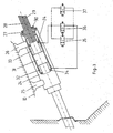
- a steering spindle 1 is in a casing tube 2 rotatable but immobile in the axial direction stored.
- the casing tube 2 is in the direction of it Longitudinal axis movably guided on a holding part 3.
- two connecting parts 4, 5 are fastened to the casing tube 2, e.g. welded, each having a guide pin 6, 7.
- Each guide pin engages in a slot 8, 9 in Holding part 3.
- the holding part 3 is on a cross member 10 of the Motor vehicle attached, largely in a crash maintains its position, so that the holding part 3 is stable.
- the steering spindle is stored in the bulkhead 14 is unnecessary, so that the steering system in their crash behavior largely independent of the bulkhead deformation is.
- a Energy absorption element in the form of a piston-cylinder arrangement intended.
- a cylinder 11 with the Holding part 3 and a piston 12 connected to the guide pin 6.
- This piston-cylinder arrangement can be used for energy absorption in the event of a crash, also for adjusting the steering spindle be used.
- a lever 13 is provided which extends around the guide pin 6 is pivotable.
- Upper part 15 of the lever 13 is a valve, not shown actuated. Opening the valve can drain hydraulic fluid via a line 16 into a vessel, not shown flow so that the piston moves slightly in the cylinder leaves.
- the entire pedals of the motor vehicle is one Auxiliary carrier 17 also connected to the holding part 3, by the upper end 18 pivotally attached to the holding part 3 is.
- the Pedals At the lower end 19 of the subcarrier are the Pedals, of which only one pedal 20 can be seen, can be pivoted arranged.
- the Subcarrier 17 In its middle section is the Subcarrier 17 with a lever 21 and a clamp 22 with connected to the casing tube 2. By releasing the clamp 22 the entire pedals can be swiveled and at the driver's request can be set. When the clamp is fixed, the Subcarrier 17 firmly connected to the casing tube 2.
- a support 23 for a switch unit attached At the upper end of the casing tube 2 is a support 23 for a switch unit attached.
- This carrier is said to be additional the steering wheel deformation in the upper steering wheel rim area hinder, so a crash-optimized deformation behavior to achieve the steering wheel over the entire steering angle range.
- a jacket tube 24 is provided that via connecting parts 25, 26 to the cross member 10 connected is.
- a steering column is mounted in the casing tube 24, which consists of two parts, these parts being one Form piston-cylinder arrangement. So part is as Formed socket 27 ', which is rotatably supported in the casing tube 24 is.
- the steering spindle runs through this beech 27 28, which is axially displaceably mounted in the bushing 27 is.
- the torque applied to the steering wheel is determined by a serration 29 on the circumference of the steering shaft 28 and a corresponding serration 30 in the socket 27 transfer this.
- the inner diameter of the sleeve 27 is in the middle Range larger than the diameter of the steering spindle 28.
- This gap is created by one on the steering shaft provided piston 31 divided into two chambers 32, 33, which are sealed to the outside by sealing elements 34. Both chambers are via valves 35 connected in parallel, 36, 37 connected to each other.
- a closed volume of a suitable one Medium preferably a liquid.
- a suitable one Medium preferably a liquid.
- the basic position is the connection between the chambers 32, 33 interrupted, i.e. the axial displacement of the Steering spindle 28 and thus the steering wheel, not shown is locked. All for a steering column adjustment Valves brought into their working position in which they are one have predetermined flow cross-section. So that is axial displacement possible with little effort, by moving the medium from chamber 32 into chamber 33 or vice versa.
- the piston-cylinder arrangement of the Steering column as an energy absorption element for energy reduction one directly or indirectly via an unfolded one Airbag impacting occupants on the steering wheel.
- the valve system enables independent adjustment of the Damping behavior to the severity of the accident.
- Dependence on the mass and the relative speed the occupant has a different number of valves 35, 36, 37 brought into their working position and thus the flow cross-section varied. A displacement of the medium from the chamber 32 to the chamber 33 is thus on a different Force level possible.
- the position of the necessary number Valves are made using sensors, not shown and an associated control circuit known per se.
- valve arrangement described can also be used for control the piston-cylinder arrangement of Fig. 1 can be used.
Landscapes
- Engineering & Computer Science (AREA)
- Mechanical Engineering (AREA)
- Transportation (AREA)
- Chemical & Material Sciences (AREA)
- Combustion & Propulsion (AREA)
- Physics & Mathematics (AREA)
- General Physics & Mathematics (AREA)
- Automation & Control Theory (AREA)
- Steering Controls (AREA)
- Air Bags (AREA)
Claims (9)
- Dispositif de sécurité pour occupant sur le côté conducteur d'un véhicule automobile, dans lequel l'arbre de direction (1) est guidé dans un tube enveloppe (2) et dans lequel il est prévu un volant avec airbag, l'arbre de direction (1) étant agencé mobile en direction de son axe longitudinal, et au moins un élément d'absorption d'énergie (11, 12 ; 31, 32, 33), autoadaptable à la masse et à la vitesse relative de l'occupant percutant le volant ou l'airbag, étant associé audit arbre de direction,
caractérisé en ce que
le tube enveloppe (2) est guidé à déplacement sur au moins une partie de retenue (3) qui est reliée à une traverse de véhicule (10) pratiquement indéplaçable en cas de collision, en ce que l'élément d'absorption d'énergie (11, 12) est agencé entre le tube enveloppe (2) et la partie de retenue (3), l'arbre de direction (1) est indéplaçable dans le tube enveloppe (2), et en ce qu'il est prévu un support auxiliaire de pédales (17) qui est fixé avec une extrémité (18) sur la partie de retenue (3) de manière à pivoter, qui est par ailleurs fixé de manière à pivoter sur le tube enveloppe (2) et à l'autre extrémité (19) duquel sont fixées les pédales d'embrayage, de frein et d'accélérateur (20). - Dispositif de sécurité pour occupant selon la revendication 1, caractérisé en ce que la partie de retenue (3) reliée à la traverse de véhicule (10) présente au moins une fente (8, 9) dans laquelle s'engage un goujon de guidage (6, 7) relié au tube enveloppe (2), et en ce qu'il est prévu en tant qu'élément d'absorption d'énergie un agencement hydraulique avec piston (12) et cylindre (11), le piston (12) étant relié au tube enveloppe (2) ou à la partie de retenue (3) et le cylindre étant relié avec l'autre partie respective.
- Dispositif de sécurité pour occupant selon l'une ou l'autre des revendications 1 et 2, caractérisé en ce que la partie de retenue (3) présente deux fentes (8, 9) s'étendant sensiblement en direction de l'axe longitudinal du tube enveloppe (2), auxquelles est associé un goujon de guidage (6, 7) respectif, chaque goujon de guidage étant fixé à une partie de rattachement (4, 5) reliée au tube enveloppe.
- Dispositif de sécurité pour occupant selon au moins une quelconque des revendications précédentes, caractérisé en ce que le tube enveloppe (2) présente à son extrémité tournée vers l'occupant au moins un support (23) pour une unité de commutateurs.
- Dispositif de sécurité pour occupant selon au moins une quelconque des revendications précédentes, caractérisé en ce que le support auxiliaire de pédales (17) est relié au tube enveloppe (2) par un dispositif de serrage (22).
- Dispositif de sécurité pour occupant selon au moins une quelconque des revendications précédentes, caractérisé en ce que la chambre cylindrique est subdivisée par le piston en deux chambres (32, 33) qui peuvent être reliées l'une à l'autre par au moins une soupape (35, 36, 37).
- Dispositif de sécurité pour occupant selon la revendication 6, caractérisé en ce qu'il est prévu plusieurs soupapes (35, 36, 37) branchées en parallèle.
- Dispositif de sécurité pour occupant selon l'une ou l'autre des revendications 6 et 7, caractérisé en ce qu'en fonction de la masse et de la vitesse relative de l'occupant, l'écoulement est libéré par un nombre différent de soupapes (35, 36, 37) qui sont actionnables par des capteurs et par une commande associée.
- Dispositif de sécurité pour occupant selon au moins une des revendications 6 à 8, caractérisé en ce qu'il est prévu au moins une soupape à section transversale variable.
Applications Claiming Priority (3)
| Application Number | Priority Date | Filing Date | Title |
|---|---|---|---|
| DE19749970A DE19749970A1 (de) | 1997-11-05 | 1997-11-05 | Insassen-Sicherheitsvorrichtung für die Fahrerseite eines Kraftfahrzeuges |
| DE19749970 | 1997-11-05 | ||
| PCT/DE1998/003211 WO1999024305A1 (fr) | 1997-11-05 | 1998-10-28 | Dispositif de protection pour le siege conducteur d'un vehicule automobile |
Publications (2)
| Publication Number | Publication Date |
|---|---|
| EP1027246A1 EP1027246A1 (fr) | 2000-08-16 |
| EP1027246B1 true EP1027246B1 (fr) | 2002-05-08 |
Family
ID=7848388
Family Applications (1)
| Application Number | Title | Priority Date | Filing Date |
|---|---|---|---|
| EP98959779A Expired - Lifetime EP1027246B1 (fr) | 1997-11-05 | 1998-10-28 | Dispositif de protection pour le siege conducteur d'un vehicule automobile |
Country Status (6)
| Country | Link |
|---|---|
| US (1) | US6375220B1 (fr) |
| EP (1) | EP1027246B1 (fr) |
| JP (1) | JP3522687B2 (fr) |
| BR (1) | BR9813956A (fr) |
| DE (2) | DE19749970A1 (fr) |
| WO (1) | WO1999024305A1 (fr) |
Families Citing this family (24)
| Publication number | Priority date | Publication date | Assignee | Title |
|---|---|---|---|---|
| US6152488A (en) * | 1999-06-16 | 2000-11-28 | Ford Global Technologies, Inc. | Steering column with variable collapse force |
| JP2001058552A (ja) * | 1999-08-04 | 2001-03-06 | Takata Corp | 車両衝突被害軽減システム |
| DE10001420A1 (de) * | 2000-01-15 | 2001-07-19 | Schenck Ag Carl | Passives Kraftelement auf Basis elektrorheologischer Flüssigkeiten |
| US6726248B2 (en) * | 2000-05-16 | 2004-04-27 | Nsk Ltd. | Impact absorbing type steering column apparatus |
| DE10100726A1 (de) * | 2001-01-10 | 2002-07-11 | Suspa Holding Gmbh | Lenksäulendämpfer |
| JP3895566B2 (ja) * | 2001-08-07 | 2007-03-22 | 本田技研工業株式会社 | 車両用ステアリング装置 |
| KR100405559B1 (ko) * | 2001-09-20 | 2003-11-14 | 현대자동차주식회사 | 자동차의 브레이크페달 밀림 방지구조 |
| WO2003033328A2 (fr) * | 2001-10-16 | 2003-04-24 | Delphi Technologies, Inc. | Systeme reactif a absorption d'energie pour colonnes de direction |
| US6652002B2 (en) * | 2001-10-19 | 2003-11-25 | Delphi Technologies, Inc. | Crash responsive energy absorbing device for a steering column |
| US6908110B2 (en) * | 2002-03-28 | 2005-06-21 | Delphi Technologies, Inc. | Programmable energy absorbing system |
| AU2003293572A1 (en) * | 2002-12-13 | 2004-07-09 | Takata-Petri, Inc. | Steering column module |
| US7185918B2 (en) * | 2003-01-31 | 2007-03-06 | Delphi Technologies, Inc. | Linear tracking column module with pedal assembly |
| US7063354B2 (en) * | 2003-01-31 | 2006-06-20 | Delphi Technologies, Inc. | Linear tracking column module |
| DE60304466T2 (de) * | 2003-08-29 | 2006-10-19 | Autotech Engineering, A.I.E., Abadino | Mechanismus für Freischaltung des Bremspedals eines Fahrzeuges bei Kollision |
| US20060107784A1 (en) * | 2003-12-16 | 2006-05-25 | Takata-Petri, Inc. | Steering column module |
| KR100986497B1 (ko) * | 2004-11-26 | 2010-10-11 | 현대자동차주식회사 | 운전자 보호장치 |
| JP4379463B2 (ja) * | 2006-10-31 | 2009-12-09 | トヨタ自動車株式会社 | コラム付けニーエアバッグ装置 |
| DE102007026378A1 (de) | 2007-05-21 | 2008-11-27 | Fludicon Gmbh | Schwingungsdämpfer |
| US7987743B2 (en) * | 2008-12-19 | 2011-08-02 | Ventra Group, Inc. | Positive release crash pedal mechanism |
| DE102013003841B4 (de) | 2012-12-21 | 2016-11-24 | Fludicon Gmbh | Schwingungsdämpfer |
| US9523998B2 (en) | 2013-03-14 | 2016-12-20 | Ventra Group Co. | Safety release system for pedals |
| US9889826B2 (en) | 2014-02-19 | 2018-02-13 | Ventra Group Co. | Variable ratio brake pedal |
| US10029642B2 (en) * | 2016-03-18 | 2018-07-24 | Hyundai America Technical Center, Inc | Enhanced steering system utilizing fixed dab for occupant protection in frontal impacts with laterial loading |
| DE102020204802A1 (de) | 2020-04-16 | 2021-10-21 | Thyssenkrupp Ag | Lenksäule für ein Kraftfahrzeug |
Family Cites Families (19)
| Publication number | Priority date | Publication date | Assignee | Title |
|---|---|---|---|---|
| US3563111A (en) * | 1968-07-24 | 1971-02-16 | Gen Motors Corp | Adjustable control pedals |
| DE2204628A1 (de) | 1972-02-01 | 1973-08-09 | Kiekert Soehne Arn | Verstellbare bedienungseinheit fuer kraftfahrzeuge |
| DE2205014A1 (de) * | 1972-02-03 | 1973-08-09 | Daimler Benz Ag | Lenkungsanordnung fuer kraftfahrzeuge insbesondere fuer personenkraftwagen |
| DE2417543A1 (de) * | 1974-04-10 | 1975-10-30 | Porsche Ag | Sicherheits- lenkungsanordnung fuer kraftfahrzeuge, insb. fuer personenkraftwagen |
| IT1021290B (it) * | 1974-09-11 | 1978-01-30 | Alfa Romeo Alfasud | Dispositivo di sicurezza per si stema di sterzo di autoveicolo |
| US4674354A (en) * | 1985-10-15 | 1987-06-23 | Brand Harold E | Collapsible steering column |
| US4886295A (en) * | 1988-12-05 | 1989-12-12 | General Motors Corporation | Vehicle occupant protection system |
| DE3935832C1 (fr) * | 1989-10-27 | 1990-12-13 | Mercedes-Benz Aktiengesellschaft, 7000 Stuttgart, De | |
| DE4038010A1 (de) * | 1990-11-29 | 1992-06-04 | Stabilus Gmbh | Hydraulisch verstellbare lenksaeule |
| US5351573A (en) * | 1991-10-07 | 1994-10-04 | Cicotte Edmond B | Adjustable automobile pedal system |
| DE4133960C2 (de) * | 1991-10-14 | 1996-08-01 | Reiche & Co | Sicherheitsvorrichtung für Kraftfahrzeug-Lenksäulen |
| DE4235588A1 (de) * | 1992-10-22 | 1994-04-28 | Stabilus Gmbh | Hydropneumatisches Verstellelement |
| DE4340633C2 (de) * | 1992-12-03 | 2003-04-10 | Opel Adam Ag | Rückholsystem für das Pedalsystem und/oder die Lenksäule von Kfz. |
| FR2707583B1 (fr) * | 1993-07-16 | 1995-10-20 | Ecia Equip Composants Ind Auto | Ensemble de colonne de direction rétractable axialement en cas de choc, notamment pour véhicule automobile. |
| FR2714651B1 (fr) * | 1994-01-06 | 1996-03-15 | Nacam | Dispositif d'absorption d'énergie pour colonne de direction de véhicule automobile. |
| US5562306A (en) * | 1994-03-18 | 1996-10-08 | Dr. Ing. H.C.F. Porsche Ag | Adjustable steering device |
| DE19501859A1 (de) | 1995-01-23 | 1996-07-25 | Volkswagen Ag | Sicherheitsanordnung für ein Kraftfahrzeug |
| DE19819712A1 (de) * | 1998-05-02 | 1999-11-11 | Daimler Chrysler Ag | Stellzylinder für eine Lenkungsanordnung eines Kraftfahrzeugs |
| GB9817536D0 (en) * | 1998-08-13 | 1998-10-07 | Rover Group | A motor vehicle |
-
1997
- 1997-11-05 DE DE19749970A patent/DE19749970A1/de not_active Withdrawn
-
1998
- 1998-10-28 DE DE59804084T patent/DE59804084D1/de not_active Expired - Fee Related
- 1998-10-28 BR BR9813956-8A patent/BR9813956A/pt active Search and Examination
- 1998-10-28 JP JP2000520341A patent/JP3522687B2/ja not_active Expired - Fee Related
- 1998-10-28 WO PCT/DE1998/003211 patent/WO1999024305A1/fr not_active Ceased
- 1998-10-28 EP EP98959779A patent/EP1027246B1/fr not_active Expired - Lifetime
- 1998-10-28 US US09/530,853 patent/US6375220B1/en not_active Expired - Fee Related
Also Published As
| Publication number | Publication date |
|---|---|
| JP3522687B2 (ja) | 2004-04-26 |
| US6375220B1 (en) | 2002-04-23 |
| BR9813956A (pt) | 2000-09-26 |
| DE19749970A1 (de) | 1999-05-12 |
| EP1027246A1 (fr) | 2000-08-16 |
| DE59804084D1 (de) | 2002-06-13 |
| JP2001522759A (ja) | 2001-11-20 |
| WO1999024305A1 (fr) | 1999-05-20 |
Similar Documents
| Publication | Publication Date | Title |
|---|---|---|
| EP1027246A1 (fr) | Dispositif de protection pour le siege conducteur d'un vehicule automobile | |
| DE102015204476B3 (de) | Lenksäule für ein Kraftfahrzeug | |
| DE602004009678T2 (de) | Stossdämpfungs-lenkvorrichtung | |
| DE102006040396B4 (de) | Lenkungssystem | |
| EP2318239B1 (fr) | Colonne de direction réglable pour véhicule à moteur | |
| DE60110870T2 (de) | Stossenergie aufnehmende Lenksäule | |
| EP1178916A1 (fr) | Ensemble capot avant | |
| DE102010052909B4 (de) | Feststellvorrichtung für verstellbare Kraftfahrzeuglenksäule | |
| EP2231463B1 (fr) | Ensemble colonne de direction pour véhicules automobiles | |
| EP0424629B1 (fr) | Dispositif d'arrêt détachable pour la colonne de direction ajustable en longueur d'une voiture | |
| DE69500814T2 (de) | Energieabsorbierende Einrichtung für eine Kraftfahrzeuglenksäule | |
| DE19819712A1 (de) | Stellzylinder für eine Lenkungsanordnung eines Kraftfahrzeugs | |
| DE3149113A1 (de) | Sicherheitseinrichtung fuer fahrzeuge | |
| EP1420979B1 (fr) | Disposition d'un appui-tete sur le siege d'un vehicule, notamment en cas d'accident avec impact arriere | |
| DE10341604B4 (de) | Lenksäulenanordnung mit einer in ihrer Neigung und Länge veränderbaren Lenksäule | |
| DE102007028770B4 (de) | Lenksäulenanordnung für ein Kraftfahrzeug | |
| DE10343399B3 (de) | Lenksäulenanordnung | |
| DE10141078C1 (de) | Sicherheitslenksäule für ein Kraftfahrzeug | |
| EP1868869B1 (fr) | Disposition d'une colonne de direction | |
| DE102004024876B4 (de) | Lenksäulenanordnung mit einer in ihrer Neigung und Länge veränderbaren Lenksäule | |
| DE2141148C2 (de) | Der Instrumententafel eines Kraftwagens zugeordnete Rückhaltevorrichtung | |
| DE10313470B3 (de) | Lenksäulenanordnung für ein Kraftfahrzeug | |
| WO2005028279A1 (fr) | Ensemble colonne de direction comprenant une colonne de direction a inclinaison et longueur modifiables | |
| WO2004089686A1 (fr) | Siege de vehicule reglable en hauteur | |
| DE10343137A1 (de) | Verstellbares Fußhebelwerk |
Legal Events
| Date | Code | Title | Description |
|---|---|---|---|
| PUAI | Public reference made under article 153(3) epc to a published international application that has entered the european phase |
Free format text: ORIGINAL CODE: 0009012 |
|
| 17P | Request for examination filed |
Effective date: 20000221 |
|
| AK | Designated contracting states |
Kind code of ref document: A1 Designated state(s): DE ES FR GB |
|
| GRAG | Despatch of communication of intention to grant |
Free format text: ORIGINAL CODE: EPIDOS AGRA |
|
| RAP1 | Party data changed (applicant data changed or rights of an application transferred) |
Owner name: TAKATA-PETRI AG |
|
| GRAG | Despatch of communication of intention to grant |
Free format text: ORIGINAL CODE: EPIDOS AGRA |
|
| GRAH | Despatch of communication of intention to grant a patent |
Free format text: ORIGINAL CODE: EPIDOS IGRA |
|
| 17Q | First examination report despatched |
Effective date: 20011009 |
|
| REG | Reference to a national code |
Ref country code: GB Ref legal event code: IF02 |
|
| GRAH | Despatch of communication of intention to grant a patent |
Free format text: ORIGINAL CODE: EPIDOS IGRA |
|
| GRAA | (expected) grant |
Free format text: ORIGINAL CODE: 0009210 |
|
| AK | Designated contracting states |
Kind code of ref document: B1 Designated state(s): DE ES FR GB |
|
| REF | Corresponds to: |
Ref document number: 59804084 Country of ref document: DE Date of ref document: 20020613 |
|
| GBT | Gb: translation of ep patent filed (gb section 77(6)(a)/1977) |
Effective date: 20020720 |
|
| ET | Fr: translation filed | ||
| PG25 | Lapsed in a contracting state [announced via postgrant information from national office to epo] |
Ref country code: ES Free format text: LAPSE BECAUSE OF FAILURE TO SUBMIT A TRANSLATION OF THE DESCRIPTION OR TO PAY THE FEE WITHIN THE PRESCRIBED TIME-LIMIT Effective date: 20021128 |
|
| PGFP | Annual fee paid to national office [announced via postgrant information from national office to epo] |
Ref country code: DE Payment date: 20030310 Year of fee payment: 6 |
|
| PLBE | No opposition filed within time limit |
Free format text: ORIGINAL CODE: 0009261 |
|
| STAA | Information on the status of an ep patent application or granted ep patent |
Free format text: STATUS: NO OPPOSITION FILED WITHIN TIME LIMIT |
|
| 26N | No opposition filed |
Effective date: 20030211 |
|
| PGFP | Annual fee paid to national office [announced via postgrant information from national office to epo] |
Ref country code: GB Payment date: 20031006 Year of fee payment: 6 |
|
| PGFP | Annual fee paid to national office [announced via postgrant information from national office to epo] |
Ref country code: FR Payment date: 20031021 Year of fee payment: 6 |
|
| PG25 | Lapsed in a contracting state [announced via postgrant information from national office to epo] |
Ref country code: GB Free format text: LAPSE BECAUSE OF NON-PAYMENT OF DUE FEES Effective date: 20041028 |
|
| PG25 | Lapsed in a contracting state [announced via postgrant information from national office to epo] |
Ref country code: DE Free format text: LAPSE BECAUSE OF NON-PAYMENT OF DUE FEES Effective date: 20050503 |
|
| GBPC | Gb: european patent ceased through non-payment of renewal fee |
Effective date: 20041028 |
|
| PG25 | Lapsed in a contracting state [announced via postgrant information from national office to epo] |
Ref country code: FR Free format text: LAPSE BECAUSE OF NON-PAYMENT OF DUE FEES Effective date: 20050630 |
|
| REG | Reference to a national code |
Ref country code: FR Ref legal event code: ST |