EP1027578B1 - Verfahren und anordnung zur rechnergestüzten bearbeitung eines graphen - Google Patents
Verfahren und anordnung zur rechnergestüzten bearbeitung eines graphen Download PDFInfo
- Publication number
- EP1027578B1 EP1027578B1 EP98955377A EP98955377A EP1027578B1 EP 1027578 B1 EP1027578 B1 EP 1027578B1 EP 98955377 A EP98955377 A EP 98955377A EP 98955377 A EP98955377 A EP 98955377A EP 1027578 B1 EP1027578 B1 EP 1027578B1
- Authority
- EP
- European Patent Office
- Prior art keywords
- node
- starting
- region
- destination
- nodes
- Prior art date
- Legal status (The legal status is an assumption and is not a legal conclusion. Google has not performed a legal analysis and makes no representation as to the accuracy of the status listed.)
- Expired - Lifetime
Links
- 238000000034 method Methods 0.000 title claims description 37
- 238000012545 processing Methods 0.000 title claims description 6
- OKTJSMMVPCPJKN-UHFFFAOYSA-N Carbon Chemical compound [C] OKTJSMMVPCPJKN-UHFFFAOYSA-N 0.000 description 22
- 229920001817 Agar Polymers 0.000 description 14
- 238000007781 pre-processing Methods 0.000 description 9
- 230000002457 bidirectional effect Effects 0.000 description 2
- 238000011156 evaluation Methods 0.000 description 2
- 230000006870 function Effects 0.000 description 2
- 241001136792 Alle Species 0.000 description 1
- 230000006399 behavior Effects 0.000 description 1
- 238000004364 calculation method Methods 0.000 description 1
- 230000001419 dependent effect Effects 0.000 description 1
- 238000011161 development Methods 0.000 description 1
- 230000018109 developmental process Effects 0.000 description 1
- 238000010586 diagram Methods 0.000 description 1
- 229910021389 graphene Inorganic materials 0.000 description 1
- 238000013507 mapping Methods 0.000 description 1
- 238000012986 modification Methods 0.000 description 1
- 230000004048 modification Effects 0.000 description 1
- 230000008685 targeting Effects 0.000 description 1
- 238000012549 training Methods 0.000 description 1
Images





Classifications
-
- G—PHYSICS
- G01—MEASURING; TESTING
- G01C—MEASURING DISTANCES, LEVELS OR BEARINGS; SURVEYING; NAVIGATION; GYROSCOPIC INSTRUMENTS; PHOTOGRAMMETRY OR VIDEOGRAMMETRY
- G01C21/00—Navigation; Navigational instruments not provided for in groups G01C1/00 - G01C19/00
- G01C21/26—Navigation; Navigational instruments not provided for in groups G01C1/00 - G01C19/00 specially adapted for navigation in a road network
- G01C21/34—Route searching; Route guidance
- G01C21/3446—Details of route searching algorithms, e.g. Dijkstra, A*, arc-flags or using precalculated routes
Definitions
- the invention relates to a computer-assisted processing of a Graph that has nodes and edges.
- One is used in a wide variety of computer-aided applications fast, computer-aided determination of shortest paths in directional or undirected graphs needed.
- [3] is a computer-aided navigation system in a motor vehicle (Kfz) known.
- maps are stored, with individual ones Places on the map (e.g. houses, train stations, sights, etc.) are represented by nodes of a graph.
- the connections between the places (streets, paths, etc.) are represented by edges of the graph.
- From [4] is a method for mapping a graph into a Memory through a number of depth and breadth searches known in different directions.
- [5] is a location database for the determination of routes known within a traffic network.
- the known navigation system has the disadvantage that an optimized route, i.e. the shortest path between the Starting position and the target position only with very high computing effort is to be determined so that with fast processing a job for route determination considerable computing power must be made available, whereby the navigation system is considerably expensive.
- a central server In centralized systems, a central server must have a Variety of inquiries for route determination of a variety of Operate client navigation systems and a large number of them can determine the shortest paths quickly.
- the invention is therefore based on the problem of a graph, which has knots and edges to process in such a way that a shortest path can be determined more quickly than is possible with the known methods.
- the shortest path can contain shortest paths in the tree be or in another shortest path to the root node, which is not included in the shortest path in the tree.
- any method can be used to determine shortest paths, e.g. the Moore / Pape process or also the Dijkstra algorithm in the respective application also bidirectional with or without targeting Distance to go estimation, or any other method for Determination of shortest paths can be used.
- Figure 1 shows a map LK, the content of a Graph G is represented with nodes KN and edges KA.
- the Nodes KN of the graph G represent positions within the map, buildings, sights, etc.
- the edges KA represent roads, generally connections between the positions on the map LK.
- the nodes KN are in three areas H, M, B grouped, a first area M that the Represented urban area of Kunststoff, a second area H, that represents the urban area of Hamburg, as well as a City area B, which represents the city of Berlin.
- FIG. 2 shows a sketch of a navigation system N.
- the navigation system N has a control panel BT, a Display unit OFF, a processor unit P, a bus BU, a GPS system (Global Positioning System) and a memory SP, on.
- a GPS system Global Positioning System
- the navigation system N is operated with the control panel BT.
- Both the display unit AUS, and the processor P, the GPS system GPS as well as the memory SP are on a bus BU coupled together.
- the maps LKj are in digital form in the memory SP saved.
- the maps LKj can also be stored on other storage media, which is not directly integrated in the navigation system N. are, e.g. a CD-ROM.
- the navigation system N is in a cockpit A of a motor vehicle built-in.
- the cockpit A has a steering wheel L 1 Dashboard AB and a console K on.
- the navigation system N is integrated in the console K, just like a radio R.
- a user of the navigation system uses the control panel BT N a desired starting position and a desired one Target position specified on the map LKj for which the user can determine the best possible route would like to.
- the route determination is based on a method to determine the shortest paths in the graph G that the Content of the map LKj represents.
- the nodes KN of the graph G are in any number of Areas M, H, B, grouped.
- the areas represent one logically related set of positions within the Map LKj.
- Each node KN of the graph G becomes exactly one area M, H, B grouped.
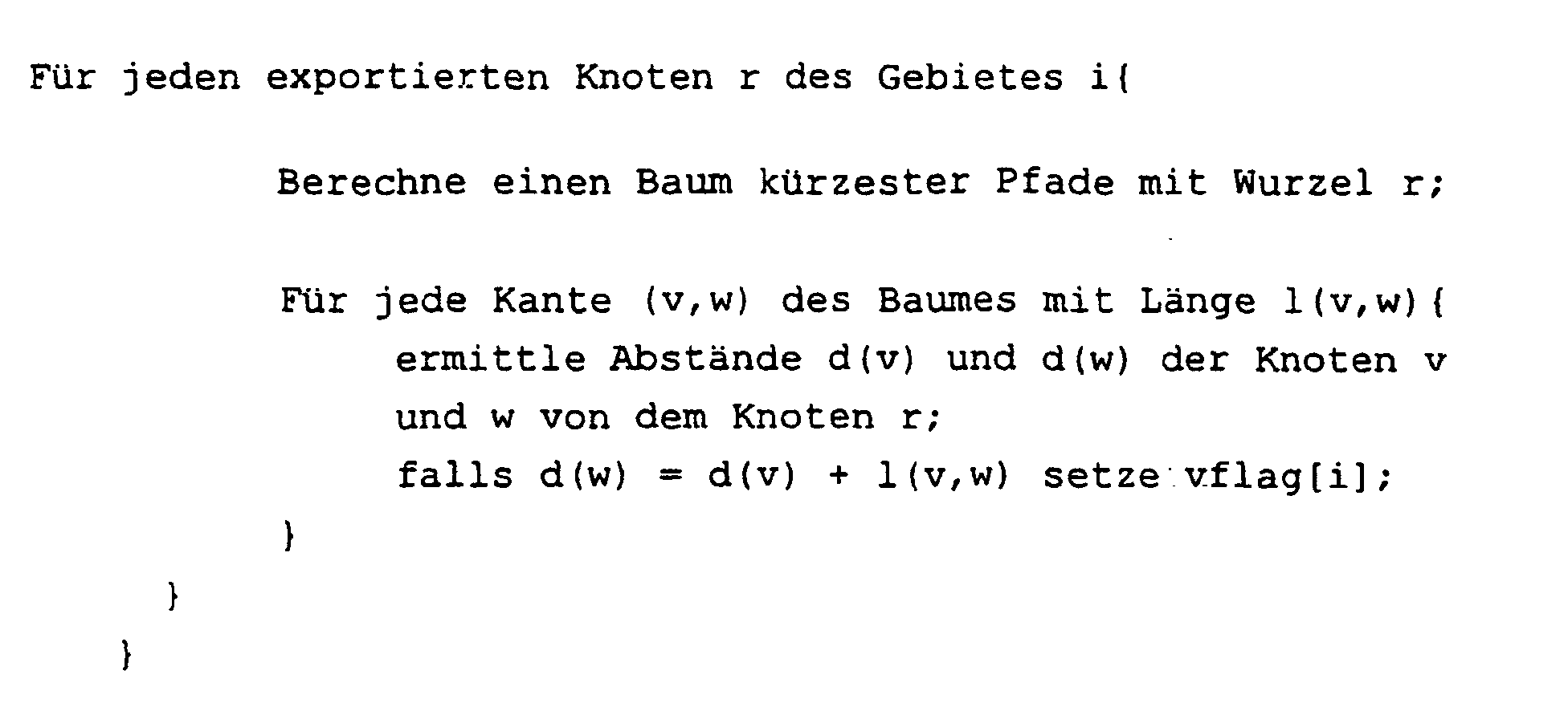
- a first node value vflag [i] of a node v of the respective Edge (v, w) is then and only then on a first binary Value set, i.e. the node v marks if it's a shortest Path from node v that uses the edge (v, w) and leads to a target area i.
- a second node value wflag [i] is only set if it is the shortest Path from node w that uses the edge (v, w) and leads to the target area i.
- the graph 1301 has 8 nodes a, b, c, d, e, f, g, h on.
- the 8 knots are in three areas R1, R2, R3 grouped.
- a first area R1 contains the nodes a, b, c
- a second area R2 contains the nodes d, e, f
- a third area R3 contains nodes g and h.
- a tree of shortest paths 501 with the root node c is in Fig. 5a shown.
- a tree's shortest paths is in the graph by a second connection between the nodes of graph 1301.
- the regions R1, R2, R3 are also shown in 3 main columns. There are two in each main column R1, R2, R3 Columns v, w contain the first node value and the second, respectively Node value of the respective edge (v, w) in the region R1, Represent R2, R3.
- a first node value in a field that is denoted by a Edge (v, w) and a main column and a column in one Main column is indicated by a cross in each Field shown.
- a first node value is then marked if starting from the vertex of the edge (v, w) shortest path leads to the root node c that the respective Edge (v, w) contains.
- the edge (a, b) is not the shortest Path to the root node c included.
- this tree shortest paths 501 for the edge (a, b) none Marking set.
- the edge (a, c) it is determined that the edge (a, c) in contains the shortest paths 501 with the root node c is. Starting from node a, a shortest path is included the edge (a, c) to the root node c. Thus the knot a marked for the first region R1 since the target area is the first Region R1 is.
- the edge (b, d) is not in the shortest path tree 501 with root node c included. For the edge (c, b) it holds that starting from node b, a shortest path with the edge (c, b) leads to the root node c. Thus the node b marked for the first region R1.
- edges (c, e) and (c, g) The same applies to the edges (c, e) and (c, g).
- Edge (d, e) holds that starting from the node d is a shortest Path to the root node c exists, with the edges (d, e) and (c, e).
- the edge (d, e) is included in the shortest path and the node d is for the edge for the first region R1 marked.
- a tree of shortest paths 701 with the root node b is in Figure 7a shown and the associated markings for the first region R1 for the respective edges with respect to the tree
- the shortest paths 701 with root node b are shown in FIG. 7b.
- Figure 8a is a tree of shortest paths 801 with the root node d shown in the second region R2.
- Figure 8b shows the markings for the second region R2 in the corresponding Table.
- a tree of shortest paths 901 with root node f is shown in the figure 9a and the corresponding table according to that described above The method is shown in FIG. 9b.
- FIG. 10a shows a tree of the shortest paths 1001 with root nodes e and FIG. 10b to the tree with the shortest paths 1001 Root node f associated table.
- FIG. 11a shows a tree of shortest paths 1101 with root nodes g and Figure 11b shows the resulting table for the third region R3 and the tree shortest paths 1101 with Root node g.
- Figure 12a shows a tree of shortest paths 1201 with root nodes h and FIG. 12 b shows the resulting table Procedures for shortest path tree described above 1201 with root node h and the third region R3.
- Figure 13b is a resulting overall table in which all marked nodes for the respective edge and the respective Territories are grouped together after a logical OR operation all tables shown in FIGS. 5b, 6b, 7b, 8b, 9b, 10b, 11b, 12b.
- An associated starting area i s in which the starting node is located, and target area i t , in which the target node is located, is determined for the given starting node and the given destination node.
- the route search thus spreads from the starting node in a very targeted manner to the target area i t and only widens out in the vicinity of the target area i t .
- a bidirectional search can be used simultaneously from the start node and from the destination node. In this way, the fanning out in the vicinity of the target area i t is also eliminated and the nodes lying in the shortest path are examined almost exclusively.
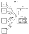
- the navigation system server NS has one Processor PNS of the navigation system server NS, and one Memory PLC with the stored maps LKj, where the memory PLC with the processor PNS of the navigation system server NS is coupled.
- Inquiries for the determination are made by the navigation systems Ni shortest paths fed to the navigation system server NS.
- Each request contains an indication of the desired starting position SPi and the desired target position ZPi for which the route should be determined.
- Finding shortest paths as well the preprocessing is done in the navigation system server NS performed and the optimal route Ri that the edges of the contains the shortest path is from the navigation system server NS the respective navigation system Ni in a reply message Ri transmitted.
- the preprocessing is independent of the number of requests only once or - if changed Traffic situations (traffic jams, road closures, etc.) should be reacted to - carried out at regular intervals will or will.
- edges in the respective graph are undirected in the exemplary embodiment.
- the arrows on the edges merely indicate an arbitrary direction.
- the invention can also be used with directed or partially directed graphs, e.g. with a road network with One-way streets are used.
Landscapes
- Engineering & Computer Science (AREA)
- Radar, Positioning & Navigation (AREA)
- Remote Sensing (AREA)
- Automation & Control Theory (AREA)
- Physics & Mathematics (AREA)
- General Physics & Mathematics (AREA)
- Navigation (AREA)
Description
- es wird ein Startgebiet ermittelt und gespeichert, zu dem der Startknoten gruppiert ist,
- es wird ein Zielgebiet ermittelt und gespeichert, zu dem der Zielknoten gruppiert ist,
- bei der Ermittlung des kürzesten Pfades ausgehend von
Startknoten und/oder ausgehend von Zielknoten werden nur die
Kanten berücksichtigt, für die gilt:
- ausgehend von dem Startknoten und/oder ausgehend von dem Zielknoten in dem Startgebiet und/oder in dem Zielgebiet ist ein erster Knoten der Kante für das Zielgebiet und/oder für das Startgebiet markiert, und
- ausgehend von dem Startknoten und/oder ausgehend von dem Zielknoten in dem Startgebiet und/oder in dem Zielgelei ist ein zweiter Knoten der Kante für das Startgebiet und/oder für das Zielgebiet markiert.
- Fig. 1
- eine Skizze einer Landkarte, deren Inhalt durch einen Graphen mit Knoten und Kanten repräsentiert wird;
- Fig. 2
- eine Skizze eines Navigationssystems;
- Fig. 3
- eine Skizze eines Cockpits eines Kraftfahrzeugs, in dem ein Navigationssystem vorgesehen ist;
- Fig. 4
- in einem Blockdiagramm eine Vielzahl von Navigationssystemen und einen Navigationsserver, dem eine Vielzahl von Anfragen zugeführt wird, für die jeweils der Server eine Route mit dem kürzesten Pfad zwischen den angegebenen Startpositionen bzw. Zielpositionen ermittelt wird;
- Fig. 5a und 5b
- eine Skizze eines Graphen mit einem Baum kürzester Pfade ausgehend von dem Knoten c (Fig. 5a) und die zugehörige Markierung der Knoten zu den jeweiligen Kanten des Graphen in der Region 1 (Fig. 5b);
- Fig. 6a und 6b
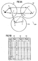
- eine Skizze eines Graphen mit einem Baum kürzester Pfade ausgehend von dem Knoten a (Fig. 6a) und die zugehörige Markierung der Knoten zu den jeweiligen Kanten des Graphen in der Region 1 (Fig. 6b);
- Fig. 7a und 7b
- eine Skizze eines Graphen mit einem Baum kürzester Pfade ausgehend von dem Knoten b (Fig. 7a) und die zugehörige Markierung der Knoten zu den jeweiligen Kanten des Graphen in der Region 1 (Fig. 7b);
- Fig. 8a und 8b
- eine Skizze eines Graphen mit einem Baum kürzester Pfade ausgehend von dem Knoten d (Fig. 8a) und die zugehörige Markierung der Knoten zu den jeweiligen Kanten des Graphen in der Region 2 (Fig. 8b);
- Fig. 9a und 9b
- eine Skizze eines Graphen mit einem Baum kürzester Pfade ausgehend von dem Knoten f (Fig. 9a) und die zugehörige Markierung der Knoten zu den jeweiligen Kanten des Graphen in der Region 2 (Fig. 9b);
- Fig. 10a und 10b
- eine Skizze eines Graphen mit einem Baum kürzester Pfade ausgehend von dem Knoten e (Fig. 10a) und die zugehörige Markierung der Knoten zu den jeweiligen Kanten des Graphen in der Region 2 (Fig. 10b);
- Fig. 11a und 11b
- eine Skizze eines Graphen mit einem Baum kürzester Pfade ausgehend von dem Knoten g (Fig. 11a) und die zugehörige Markierung der Knoten zu den jeweiligen Kanten des Graphen in der Region 3 (Fig. 11b);
- Fig. 12a und 12b
- eine Skizze eines Graphen mit einem Baum kürzester Pfade ausgehend von dem Knoten h (Fig. 12a) und die zugehörige Markierung der Knoten zu den jeweiligen Kanten des Graphen in der Region 3 (Fig. 12b);
- Fig. 13a und 13b
- eine Skizze des Graphen (Fig. 13a) und eine Tabelle mit den Kanten des Graphen und den Regionen und den entsprechenden Markierungen der Knoten der Kanten für die jeweilige Region, die sich gemäß dem Verfahren insgesamt ergibt (Fig. 13b).
- interne Kanten, bei denen beide Knoten der Kante im gleichen Gebiet liegen, und
- externe Kanten, bei denen die Knoten der Kante in verschiedenen Gebiet liegen.
Claims (15)
- Verfahren zur rechnergestützten Bearbeitung eines Graphen, der Knoten und Kanten aufweist, wobei der Graph eine Struktur eines technischen Systems beschreibt,bei dem die Knoten in mindestens zwei Gebiete gruppiert sind,bei dem für jedes Gebiet und für mindestens einen Teil der Knoten des Gebiets folgende Schritte durchgeführt werden:a) es wird ein Knoten als Wurzelknoten ausgewählt,b) für den Wurzelknoten wird ein Baum kürzester Pfade in dem Graph mit dem Wurzelknoten als Wurzel des Baums ermittelt,c) es wird ein Knoten einer Kante des Graphen für das Gebiet dann markiert, wenn ausgehend von dem Knoten zu dem Wurzelknoten die Kante in einem kürzesten Pfad zum Wurzelknoten enthalten ist, wobei die Markierung durch Zuordnung eines binären Werts zu dem Knoten in der Kante des jeweiligen Gebiets erfolgt.
- Verfahren nach Anspruch 1,
bei dem die Verfahrensschritte a) bis c) für alle Knoten des jeweiligen Gebiets durchgeführt werden. - Verfahren nach einem der Ansprüche 1 bis 2,
bei dem die Knoten in eine Vielzahl Gebiete gruppiert sind. - Verfahren nach einem der Ansprüche 1 bis 3,
bei dem unter Verwendung der markierten Knoten ein kürzester Pfad zwischen einem vorgegebenen Startknoten und einem vorgegebenen Zielknoten ermittelt wird. - Verfahren nach Anspruch 4,
bei dem zur Ermittlung des kürzesten Pfades zwischen dem Startknoten und dem Zielknoten folgende Schritte durchgeführt werden:es wird ein Startgebiet ermittelt und gespeichert, zu dem der Startknoten gruppiert ist,es wird ein Zielgebiet ermittelt und gespeichert, zu dem der Zielknoten gruppiert ist,bei der Ermittlung des kürzesten Pfades ausgehend vom Startknoten werden nur die Kanten berücksichtigt, für die gilt:ausgehend von dem Startknoten in dem Startgebiet ist ein erster Knoten der Kante für das Zielgebiet markiert, undausgehend von dem Startknoten in dem Startgebiet ist ein zweiter Knoten der Kante für das Startgebiet markiert. - Verfahren nach Anspruch 5,
bei dem zur Ermittlung des kürzesten Pfades zwischen dem Startknoten und dem Zielknoten folgende Schritte durchgeführt werden:bei der Ermittlung des kürzesten Pfades ausgehend vom Zielknoten werden nur die Kanten berücksichtigt, für die gilt:ausgehend von dem Zielknoten in dem Zielgebiet ist ein erster Knoten der Kante für das Startgebiet markiert, undausgehend von dem Zielknoten in dem Zielgebiet ist ein zweiter Knoten der Kante für das Zielgebiet markiert. - Verfahren nach einem der Ansprüche 1 bis 6,
eingesetzt zur Routenermittlung zwischen einem Startort und einem Zielort einer digitalisierten Landkarte in einem rechnergestützten Navigationssystem, wobei der Inhalt der Landkarte durch den Graphen beschrieben wird. - Verfahren nach einem der Ansprüche 1 bis 7,
bei dem zur Ermittlung eines kürzesten Pfades das Moore/Pape-Verfahren eingesetzt wird. - Anordnung zur rechnergestützten Bearbeitung eines Graphen, der Knoten und Kanten aufweist, mit einer Prozessoreinheit, die derart eingerichtet ist, daßdie Knoten in mindestens zwei Gebiete gruppiert sind,für jedes Gebiet und für mindestens einen Teil der Knoten des Gebiets folgende Schritte durchgeführt werden:a) es wird ein Knoten als Wurzelknoten ausgewählt,b) für den Wurzelknoten wird ein Baum kürzester Pfade in dem Graph mit dem Wurzelknoten als Wurzel des Baums ermittelt,c) es wird ein Knoten einer Kante des Graphen für das Gebiet dann markiert, wenn ausgehend von dem Knoten zu dem Wurzelknoten die Kante in einem kürzesten Pfad zum Wurzelknoten enthalten ist, wobei die Markierung durch Zuordnung eines binären Werts zu dem Knoten in der Kante des jeweiligen Gebiets erfolgt.
- Anordnung nach Anspruch 9,
bei der die Prozessoreinheit derart eingerichtet ist, daß die Verfahrensschritte a) bis c) für alle Knoten des jeweiligen Gebiets durchgeführt werden. - Anordnung nach einem der Ansprüche 9 bis 10,
bei der die Prozessoreinheit derart eingerichtet ist, daß die Knoten in eine Vielzahl Gebiete gruppiert sind. - Anordnung nach einem der Ansprüche 9 bis 11,
bei der die Prozessoreinheit derart eingerichtet ist, daß unter Verwendung der markierten Knoten ein kürzester Pfad zwischen einem vorgegebenen Startknoten und einem vorgegebenen Zielknoten ermittelt wird. - Anordnung nach Anspruch 12,
bei der die Prozessoreinheit derart eingerichtet ist, daß zur Ermittlung des kürzesten Pfades zwischen dem Startknoten und dem Zielknoten folgende Schritte durchgeführt werden:es wird ein Startgebiet ermittelt und gespeichert, zu dem der Startknoten gruppiert ist,es wird ein Zielgebiet ermittelt und gespeichert, zu dem der Zielknoten gruppiert ist,bei der Ermittlung des kürzesten Pfades ausgehend vom Startknoten werden nur die Kanten berücksichtigt, für die gilt:ausgehend von dem Startknoten in dem Startgebiet ist ein erster Knoten der Kante für das Zielgebiet markiert, undausgehend von dem Startknoten in dem Startgebiet ist ein zweiter Knoten der Kante für das Startgebiet markiert. - Anordnung nach Anspruch 13,
bei der die Prozessoreinheit derart eingerichtet ist, daß zur Ermittlung des kürzesten Pfades zwischen dem Startknoten und dem Zielknoten folgende Schritte durchgeführt werden:bei der Ermittlung des kürzesten Pfades ausgehend vom Zielknoten werden nur die Kanten berücksichtigt, für die gilt:ausgehend von dem Zielknoten in dem Zielgebiet ist ein erster Knoten der Kante für das Startgebiet markiert, undausgehend von dem Zielknoten in dem Zielgebiet ist ein zweiter Knoten der Kante für das Zielgebiet markiert. - Anordnung nach einem der Ansprüche 9 bis 14,bei dem eine digitalisierte Landkarte verwendet wird, wobei der Inhalt der Landkarte durch einen Graphen mit Knoten und Kanten beschrieben wird,bei dem zur Routenermittlung zwischen einem Startort und einem Zielort der Landkarte der bearbeitete Graph verwendet wird.
Applications Claiming Priority (3)
| Application Number | Priority Date | Filing Date | Title |
|---|---|---|---|
| DE19747401 | 1997-10-27 | ||
| DE19747401 | 1997-10-27 | ||
| PCT/DE1998/002965 WO1999022205A1 (de) | 1997-10-27 | 1998-10-07 | Verfahren und anordnung zur rechnergestützten bearbeitung eines graphen |
Publications (2)
| Publication Number | Publication Date |
|---|---|
| EP1027578A1 EP1027578A1 (de) | 2000-08-16 |
| EP1027578B1 true EP1027578B1 (de) | 2004-03-17 |
Family
ID=7846754
Family Applications (1)
| Application Number | Title | Priority Date | Filing Date |
|---|---|---|---|
| EP98955377A Expired - Lifetime EP1027578B1 (de) | 1997-10-27 | 1998-10-07 | Verfahren und anordnung zur rechnergestüzten bearbeitung eines graphen |
Country Status (4)
| Country | Link |
|---|---|
| US (1) | US6636800B1 (de) |
| EP (1) | EP1027578B1 (de) |
| DE (1) | DE59811014D1 (de) |
| WO (1) | WO1999022205A1 (de) |
Families Citing this family (10)
| Publication number | Priority date | Publication date | Assignee | Title |
|---|---|---|---|---|
| US7392258B2 (en) * | 2005-02-25 | 2008-06-24 | International Business Machines Corporation | Method and computer program product for dynamic weighting of an ontological data model |
| US7809754B2 (en) * | 2005-02-28 | 2010-10-05 | International Business Machines Corporation | Method and computer program product for generating a lightweight ontological data model |
| JP5075577B2 (ja) * | 2007-10-29 | 2012-11-21 | 株式会社東芝 | 車両運用計画作成装置および方法 |
| FR2926880B1 (fr) * | 2008-01-24 | 2010-09-10 | Mediamobile | Estimation de plus court chemin dependant du temps dans un reseau routier |
| WO2011004026A2 (en) | 2009-07-09 | 2011-01-13 | Tomtom International Bv | Navigation devices and methods carried out thereon |
| US9109909B2 (en) | 2009-07-09 | 2015-08-18 | Tomtom International B.V. | Navigation devices |
| EP2561315B1 (de) | 2010-04-21 | 2019-10-02 | TomTom Navigation B.V. | System und verfahren zur erstellung einer strecke durch eine elektronische karte |
| EP3309514A1 (de) | 2010-04-23 | 2018-04-18 | TomTom International B.V. | Navigationsvorrichtungen und darauf ausgeführte verfahren |
| WO2016034918A1 (en) * | 2014-09-04 | 2016-03-10 | Audi Ag | Method and system for creating at least one digital map |
| US11604073B1 (en) | 2018-09-24 | 2023-03-14 | Apple Inc. | Route guidance system |
Family Cites Families (4)
| Publication number | Priority date | Publication date | Assignee | Title |
|---|---|---|---|---|
| JP2874397B2 (ja) * | 1991-03-19 | 1999-03-24 | 松下電器産業株式会社 | 経路選出装置 |
| US5878407A (en) | 1995-04-18 | 1999-03-02 | International Business Machines Corporation | Storage of a graph |
| DE19606010A1 (de) | 1996-02-17 | 1997-08-21 | Bosch Gmbh Robert | Ortsdatenbank für die Ermittlung von Routen innerhalb eines Verkehrswegenetzes |
| WO2000019680A2 (en) * | 1998-09-17 | 2000-04-06 | Tod Mcnamara | System and method for network flow optimization using traffic classes |
-
1998
- 1998-10-07 DE DE59811014T patent/DE59811014D1/de not_active Expired - Lifetime
- 1998-10-07 WO PCT/DE1998/002965 patent/WO1999022205A1/de not_active Ceased
- 1998-10-07 US US09/530,317 patent/US6636800B1/en not_active Expired - Lifetime
- 1998-10-07 EP EP98955377A patent/EP1027578B1/de not_active Expired - Lifetime
Also Published As
| Publication number | Publication date |
|---|---|
| DE59811014D1 (de) | 2004-04-22 |
| US6636800B1 (en) | 2003-10-21 |
| EP1027578A1 (de) | 2000-08-16 |
| WO1999022205A1 (de) | 1999-05-06 |
Similar Documents
| Publication | Publication Date | Title |
|---|---|---|
| DE69629451T2 (de) | Routensuchvorrichtung für Fahrzeuge | |
| DE69616002T2 (de) | Verfahren und Gerät zum Berechnen einer Route | |
| DE3882686T2 (de) | Vorbereitungssystem von knotenserien des wegendes in einem navigationsgeraet. | |
| DE3853719T2 (de) | Wegsuchverfahren für navigationssystem. | |
| DE69526825T2 (de) | Verfahren und System zur Routenauswahl | |
| DE69625084T2 (de) | Kostengebiete | |
| DE69425234T2 (de) | Fahrzeugzielführungsvorrichtung und -verfahren unter Verwendung einer Anzeigeeinheit | |
| DE69830124T2 (de) | Verfahren und Vorrichtung zur Darstellung und Verwendung von Forminformation in geographischen Datenbanken | |
| DE69129892T2 (de) | Vorrichtung für eine günstige Route-Auswahl | |
| EP1092127B1 (de) | Verfahren zur beeinflussung von quelldaten zur bestimmung einer route bei einem navigationssystem | |
| DE69828339T2 (de) | Programm zum Erzeugen von Manövern | |
| EP1113410A2 (de) | Verfahren, Bedienteil, Navigationssystem und Schnittstelle zur Darstellung von Ausschnitten einer digitalen Kartenbasis | |
| EP1027578B1 (de) | Verfahren und anordnung zur rechnergestüzten bearbeitung eines graphen | |
| DE102009006183B4 (de) | Verfahren und System zum Anpassen von Routenplanungs-Ergebnissen | |
| DE19963766A1 (de) | Verfahren zum Betrieb eines Navigationssystems | |
| EP1025423B1 (de) | Verfahren und anordnung zur ermittlung einer route von einem startpunkt zu einem zielpunkt | |
| DE102006047212A1 (de) | Navigationssystem | |
| DE3642986C2 (de) | ||
| DE4230299B4 (de) | Verfahren zur Ortung eines Landfahrzeuges | |
| DE10139549A1 (de) | Verfahren zum Ermitteln von Routen und darauf bezogenes Navigationssystem | |
| EP1526358B1 (de) | Verfahren zur Zerlegung eines Strassennetzes aus Kanten und Knoten | |
| DE102022207651B4 (de) | Erstellen eines logischen Wegenetzes in Parkräumen | |
| DE102012212815B4 (de) | Verfahren zur Auswahl und Aufbereitung von Verkehrsinformationen | |
| DE10051745A1 (de) | Verfahren zur Schätzung der Krümmung eines Wegeabschnitts | |
| DE19816585A1 (de) | Verfahren zur Routeninformation eines Endgerät-Benutzers durch Übermittlung von Routeninformationen von einer Zentrale an das Endgerät |
Legal Events
| Date | Code | Title | Description |
|---|---|---|---|
| PUAI | Public reference made under article 153(3) epc to a published international application that has entered the european phase |
Free format text: ORIGINAL CODE: 0009012 |
|
| 17P | Request for examination filed |
Effective date: 20000417 |
|
| AK | Designated contracting states |
Kind code of ref document: A1 Designated state(s): DE FR GB |
|
| 17Q | First examination report despatched |
Effective date: 20021113 |
|
| GRAP | Despatch of communication of intention to grant a patent |
Free format text: ORIGINAL CODE: EPIDOSNIGR1 |
|
| GRAS | Grant fee paid |
Free format text: ORIGINAL CODE: EPIDOSNIGR3 |
|
| GRAA | (expected) grant |
Free format text: ORIGINAL CODE: 0009210 |
|
| AK | Designated contracting states |
Kind code of ref document: B1 Designated state(s): DE FR GB |
|
| REG | Reference to a national code |
Ref country code: GB Ref legal event code: FG4D Free format text: NOT ENGLISH |
|
| GBT | Gb: translation of ep patent filed (gb section 77(6)(a)/1977) |
Effective date: 20040317 |
|
| REF | Corresponds to: |
Ref document number: 59811014 Country of ref document: DE Date of ref document: 20040422 Kind code of ref document: P |
|
| ET | Fr: translation filed | ||
| PLBE | No opposition filed within time limit |
Free format text: ORIGINAL CODE: 0009261 |
|
| STAA | Information on the status of an ep patent application or granted ep patent |
Free format text: STATUS: NO OPPOSITION FILED WITHIN TIME LIMIT |
|
| 26N | No opposition filed |
Effective date: 20041220 |
|
| REG | Reference to a national code |
Ref country code: FR Ref legal event code: PLFP Year of fee payment: 18 |
|
| REG | Reference to a national code |
Ref country code: FR Ref legal event code: PLFP Year of fee payment: 19 |
|
| REG | Reference to a national code |
Ref country code: FR Ref legal event code: PLFP Year of fee payment: 20 |
|
| PGFP | Annual fee paid to national office [announced via postgrant information from national office to epo] |
Ref country code: DE Payment date: 20171219 Year of fee payment: 20 Ref country code: FR Payment date: 20171019 Year of fee payment: 20 |
|
| PGFP | Annual fee paid to national office [announced via postgrant information from national office to epo] |
Ref country code: GB Payment date: 20171017 Year of fee payment: 20 |
|
| REG | Reference to a national code |
Ref country code: DE Ref legal event code: R071 Ref document number: 59811014 Country of ref document: DE |
|
| REG | Reference to a national code |
Ref country code: GB Ref legal event code: PE20 Expiry date: 20181006 |
|
| PG25 | Lapsed in a contracting state [announced via postgrant information from national office to epo] |
Ref country code: GB Free format text: LAPSE BECAUSE OF EXPIRATION OF PROTECTION Effective date: 20181006 |