EP1027678B1 - Lecteur optique a rotation inverse - Google Patents
Lecteur optique a rotation inverse Download PDFInfo
- Publication number
- EP1027678B1 EP1027678B1 EP97910832A EP97910832A EP1027678B1 EP 1027678 B1 EP1027678 B1 EP 1027678B1 EP 97910832 A EP97910832 A EP 97910832A EP 97910832 A EP97910832 A EP 97910832A EP 1027678 B1 EP1027678 B1 EP 1027678B1
- Authority
- EP
- European Patent Office
- Prior art keywords
- channel
- optical
- distal end
- proximal end
- axis
- Prior art date
- Legal status (The legal status is an assumption and is not a legal conclusion. Google has not performed a legal analysis and makes no representation as to the accuracy of the status listed.)
- Expired - Lifetime
Links
Images


Classifications
-
- G—PHYSICS
- G06—COMPUTING OR CALCULATING; COUNTING
- G06K—GRAPHICAL DATA READING; PRESENTATION OF DATA; RECORD CARRIERS; HANDLING RECORD CARRIERS
- G06K7/00—Methods or arrangements for sensing record carriers, e.g. for reading patterns
- G06K7/10—Methods or arrangements for sensing record carriers, e.g. for reading patterns by electromagnetic radiation, e.g. optical sensing; by corpuscular radiation
- G06K7/10544—Methods or arrangements for sensing record carriers, e.g. for reading patterns by electromagnetic radiation, e.g. optical sensing; by corpuscular radiation by scanning of the records by radiation in the optical part of the electromagnetic spectrum
- G06K7/10554—Moving beam scanning
- G06K7/10594—Beam path
- G06K7/10683—Arrangement of fixed elements
-
- G—PHYSICS
- G02—OPTICS
- G02B—OPTICAL ELEMENTS, SYSTEMS OR APPARATUS
- G02B26/00—Optical devices or arrangements for the control of light using movable or deformable optical elements
- G02B26/08—Optical devices or arrangements for the control of light using movable or deformable optical elements for controlling the direction of light
- G02B26/10—Scanning systems
- G02B26/105—Scanning systems with one or more pivoting mirrors or galvano-mirrors
-
- G—PHYSICS
- G06—COMPUTING OR CALCULATING; COUNTING
- G06K—GRAPHICAL DATA READING; PRESENTATION OF DATA; RECORD CARRIERS; HANDLING RECORD CARRIERS
- G06K7/00—Methods or arrangements for sensing record carriers, e.g. for reading patterns
- G06K7/10—Methods or arrangements for sensing record carriers, e.g. for reading patterns by electromagnetic radiation, e.g. optical sensing; by corpuscular radiation
- G06K7/10544—Methods or arrangements for sensing record carriers, e.g. for reading patterns by electromagnetic radiation, e.g. optical sensing; by corpuscular radiation by scanning of the records by radiation in the optical part of the electromagnetic spectrum
- G06K7/10554—Moving beam scanning
- G06K7/10594—Beam path
- G06K7/10603—Basic scanning using moving elements
- G06K7/10613—Basic scanning using moving elements by rotation, e.g. polygon
-
- G—PHYSICS
- G06—COMPUTING OR CALCULATING; COUNTING
- G06K—GRAPHICAL DATA READING; PRESENTATION OF DATA; RECORD CARRIERS; HANDLING RECORD CARRIERS
- G06K7/00—Methods or arrangements for sensing record carriers, e.g. for reading patterns
- G06K7/10—Methods or arrangements for sensing record carriers, e.g. for reading patterns by electromagnetic radiation, e.g. optical sensing; by corpuscular radiation
- G06K7/10544—Methods or arrangements for sensing record carriers, e.g. for reading patterns by electromagnetic radiation, e.g. optical sensing; by corpuscular radiation by scanning of the records by radiation in the optical part of the electromagnetic spectrum
- G06K7/10554—Moving beam scanning
- G06K7/10594—Beam path
- G06K7/10603—Basic scanning using moving elements
- G06K7/10673—Parallel lines
Definitions
- the present invention relates to devices for scanning and, more specifically, to devices for optical scanning along a substantially linear path.
- Optical scanning is used in a variety of applications, including writing and reading data to and from such storage media as compact discs and optical data cards.
- Optical data cards, and other types of linear-track optical data storage media store data along linear tracks. Scanning such tracks requires linear translation of either the data card or the device used to scan the data card.
- Current devices include mechanical systems, electronic systems, acousto-optical systems, electro-optical systems, and other systems for moving an optical beam along a path. Most mechanical devices employ rotating polygon mirrors or prisms, galvanometer actuators carrying mirrors, and similar devices.
- US-A-4 079 230 describes a laser scanning apparatus using a pair of prisms which are rotated about the optical axis of the laser light at the same speed but in opposite directions. The laser light passes through the prisms to be then converged into a beam spot so that a work piece is clearly scanned for laser-working.
- OPU Optical Pickup Units
- the OPUs are typically mounted on a carriage assembly which is constrained to move in a straight line parallel to a data track.
- a linear actuator imparts a force on the carriage assembly to effect the linear motion and a linear position transducer determines instantaneous OPU location and provides feedback for the velocity control function of the actuator.
- the OPU translates down the track, illuminating the data spots on the track with an optical beam and receives reflected signals by means of electro-optical components.
- Current devices require acceleration of the OPU to its operating speed at the beginning of each data track scan and deceleration of the OPU to a stop at the end of each data track. This motion is then repeated in each direction.
- Scan speed may be increased by decreasing the mass and friction associated with the OPU and carriage assembly or by increasing the force provided by the actuator.
- the OPU In addition to translating back and forth down the data tracks to read and write optical data, the OPU must provide small amplitude, high speed focus and cross-track motions. This is because the data spot size is on the order of a single micrometer diameter and the track-to-track spacing is typically on the order often micrometers. As the OPU scans along the data track, small imperfections in any realizable mechanical mechanism result in tiny motions perpendicular to the data track, and therefore failure to maintain the required alignment between the optical data and the OPU.
- optical scanning such as spinning polygon mirrors or galvanometer driven mirrors
- Other mechanical means for optical scanning are common in other applications, but are not used in scanning optical storage media for two reasons.
- Optical data storage media ordinarily require the illuminating beam to be focused to a small spot and require it to strike the surface of the medium at substantially perpendicular incidence. The resulting reflection also propagates perpendicularly back from the surface through the same optical train as the illuminating beam.
- One method attempts to circumvent this problem by deforming the card to conform to a cylindrical surface.
- the focused illumination spot follows a circle which is supposed to be coincident with a data track on the surface of the deformed card.
- the card must be bent in such a way that its surface is accurately coincident with the required cylindrical surface to within a few micrometers (otherwise the fast focus compensation mechanism will be unable to maintain acceptable focus as the spot moves along the data track).
- OMCs optical memory cards
- deforming the card may result in excessive wear on the card and may also introduce birefringence in the transparent protective covering of the data card with undesirable effects on the polarization state of the illumination and reflected beams.
- the present invention achieves its object by providing an apparatus for scanning a beam comprising the features set out in claim 1.
- the present invention also provides a method of scanning an optical beam comprising the steps set out in claim 20.
- An advantage of the present invention is that it does not require reciprocating components. Thus, it reduces drive power, reduces vibration and it offers the potential for increased speed.
- a further advantage of the invention is that it maintains the scan beam direction perpendicular to the surface of the object being scanned.
- a further advantage of the invention is that the OPU remains essentially stationary, thereby reducing vibration, drive power and design complexity.
- Optical periscopes ordinarily incorporate a pair of reflective surfaces which are parallel to one another, each of which deviates an incident beam by an angle of 90 degrees from its propagation direction. Other deviation angles may also be used if they impart a perpendicular component to the beam's propagation direction and if the combined effect of the reflective surfaces results in a beam parallel to the incoming beam. If a periscope is caused to rotate in such a way that the input beam is coincident with the axis of rotation, then the output axis will always remain parallel to the input axis, but its displacement will fall upon a circle centered on the axis of rotation.
- the displacement of the output of the second periscope from the input to the first periscope can be represented mathematically as the vector sum of the displacement due to the first periscope and the displacement due to the second.
- the resultant displacement is a function of the displacements of each periscope and their orientation angles.
- the periscopes are of equal length, and the angular measures of their orientations are constrained to be opposite one another, and the input to the second periscope is constrained to be aligned with the output of the first periscope, then as the two periscopes rotate synchronously (with angle of the same absolute magnitude, but opposite sense), the resultant displacement traces out a perfectly straight line.
- Two continuously rotating periscopes thus achieve the same effect as a start/stop linear scanner, and if they are implemented with proper consideration to static and dynamic balance, they can operate with little vibration and no requirement for acceleration or deceleration along data tracks.
- a separate mechanism To scan a set of parallel data tracks, a separate mechanism must provide relative motion between the linear scanner and the collection of data tracks.
- the track-to-track motion occurs much more slowly than the scan along the data track, and can easily be implemented via any of a number of well known translation devices, such as stepping devices and constant velocity phased devices with the along-track scanning.
- the present invention provides an apparatus for scanning a beam along a path on an object.
- the apparatus employs a first channel and a second channel.
- the first optical channel has a first proximal end and an opposite first distal end.
- the first proximal end is in optical communication with the optical beam and the first proximal end is pivotally rotatable about a first axis adjacent the fixed point.
- the second channel has a second proximal end and an opposite second distal end with the second proximal end in communication with the first distal end of the first channel.
- the second proximal end is pivotally rotatable about a second axis adjacent the first distal end of the first channel.
- a drive causes the first channel to rotate about the first axis in a first direction, which causes the second channel to rotate about the second axis in a second direction opposite the first direction.
- Optical or other focusing devices couple the beam through the first channel and the second channel out of the second distal end of the second channel toward the object.
- the first channel rotates in the first direction and the second channel rotates in the second direction
- the second distal end of the second channel reciprocates, thereby causing the beam to scan along the linear path on the object.
- the invention is an optical image scanner for scanning an optical beam along a linear path on an object.
- the scanner employs a housing having a top and an opposite bottom.
- the housing defines a first cylindrical cavity between the top and the bottom with a ring gear disposed within the cylindrical cavity and affixed to the housing.
- a light source generates an optical beam from a fixed point relative to the housing.
- a drive disk having a peripheral edge, is disposed within the first cylindrical cavity and defining a second cylindrical cavity.
- the drive disk has a first axis of rotation and defines a first optical channel having a first length, a first proximal end and a first distal end.
- the drive disk also defines a first proximal opening adjacent the first proximal end of the first optical channel, through which the first optical channel is in optical communication with the optical beam, and a first distal opening, adjacent the first distal end of the first optical channel and in optical communication with the first optical channel.
- the first proximal end of the first optical channel is pivotally rotatable about a first axis adjacent the fixed point.
- a scan disk disposed within the second cylindrical cavity and having a second axis of rotation offset from the first axis of rotation, defines a second optical channel having a second length substantially equal to the first length, a second proximal end and a second distal end.
- the scan disk also defines a second proximal opening adjacent the second proximal end of the second optical channel, through which the second optical channel is in optical communication with the first distal opening, and a second distal opening, adjacent the second distal end ofthe second optical channel and in optical communication with the second optical channel.
- the second proximal end of the second optical channel is pivotally rotatable about a second axis adjacent the first distal end of the first optical channel.
- a ring motor is coupled to the peripheral edge and causes the drive disk to rotate about the first axis of rotation in a first direction at a first rotational speed.
- a spur gear is circumferentially affixed to the scan disk and engaged with the ring gear so that as the ring motor causes the drive disk to rotate in the first direction, the spur gear is displaced along the ring gear thus causing the scan disk to rotate about the second axis in a second direction opposite the first direction at a second rotational speed substantially equal to the first rotational speed.
- Optical devices optically couple the beam from the generating means through the first optical channel and the second optical channel and out of the second distal opening toward the linear path.
- the present invention provides a method of scanning an optical beam along a linear path.
- the optical beam is generated from a fixed point.
- the beam is directed through a first optical channel having a first proximal end adjacent the fixed point and an opposite first distal end so that the beam propagates from the first proximal end of the first optical channel toward the first distal end of the first optical channel.
- the beam is then directed from the first distal end of the first optical channel through a second optical channel having a second proximal end adjacent the first distal end of the first optical channel and an opposite second distal end so that the beam propagates from the second proximal end of the second optical channel toward the second distal end of the second optical channel.
- the first optical channel is caused to rotate about the first proximal end of the first optical channel in a first direction on a primary plane.
- the second optical channel is caused to rotate about the second proximal end of the second optical channel in a second direction opposite the first direction on a secondary plane parallel to the primary plane.
- the beam is directed from the second distal end of the second optical channel toward the linear path.
- the senor (which may include a light source and a detector) and the object being scanned are stationary while the rotating components translate the optical beam down a linear path. It appears to the sensor that the object is moving linearly, while in reality neither the sensor nor the object moves. Also, the scanned beam remains substantially perpendicular to the surface being scanned and the optical path length within the apparatus remains substantially constant throughout a scan cycle.
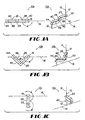
- the present invention is an apparatus 10 for scanning an optical beam 12 along a substantially linear path 16.
- the apparatus 10 comprises a first optical channel 26, which may be defined by a first periscope 20 or other elongated member, and a second optical channel 46 which may be enclosed in a second periscope 40 or other elongated member.
- the first optical channel 26 has a first proximal end 22 and an opposite first distal end 24, the first proximal end being in optical communication with the optical beam, the first proximal end being pivotally rotatable about a first axis 14 intersecting a fixed point 15.
- the second optical channel 46 has a second proximal end 42 and an opposite second distal end 44.
- the second proximal end 42 is in optical communication with the first distal end 24 of the first optical channel 26 and the second proximal end 42 is pivotally rotatable about a second axis adjacent the first distal end 24 of the first optical channel 26.
- the first optical channel 26 rotates about the first axis in a first direction
- the direction of arrow A and the second optical channel 46 rotates about the second axis in a second direction opposite the first direction, the direction of arrow B.
- the beam 12 is optically coupled through the first optical channel 26 and the second optical channel 46 out of the second distal end 44 toward the linear path 16.
- the lengths of the optical channels 26, 46 are substantially the same and if the magnitudes of angular velocity in directions A and B are substantially the same, then as the first optical channel 26 rotates in the first direction A and the second optical channel 46 rotates in the second direction B, the second distal end 44 of the second optical channel 26 linearly reciprocates, thereby causing the beam to scan along a linear path 16 on the object.
- FIGS. 1A-1F show the apparatus 10a-f at various stages of a scan.
- FIG. 1A shows the apparatus 10a fully extended to the left.
- FIG. 1B shows the apparatus 1b as the second distal end 44 tends inward.
- FIG. 1C shows the second distal end 44 substantially aligned with the first proximal end 22.
- FIG. 1D shows the second distal end 44 to the right of the first proximal end 22.
- FIG. 1E shows the second distal end 44 fully extended to the right of the first proximal end 22 and
- FIG. 1F shows the second distal end 44 tending back toward the first proximal end 22.
- This embodiment may employ optical periscopes comprising rhomboidal prisms.
- An important property of optical periscopes implemented by means of rhomboidal prisms is the relative insensitivity of the amount of beam displacement and final beam direction to angular misalignment of the periscopes.
- the 45 degree faces of rhomboidal prisms are routinely fabricated to an accuracy of about one minute of arc, and with greater care may be fabricated to an accuracy approaching one arc second.
- the length of the two rhomboidal prisms i.e., the spacing between the two 45 degree faces
- Such prisms may be fabricated by making a single prism whose width is somewhat greater than twice that required for the individual periscope prisms. Upon completing fabrication of the over-wide prism, it is simply sectioned into two prisms, which because of their common origin, are of precisely equal lengths.
- Electromagnetic wave theory requires that the minimum achievable spot resolution be approximately the wavelength multiplied by the F-number. Resolution of the small spots used in optical data storage therefore requires both a relatively short wavelength (typically less than one micrometer) as well as a low F-number (on the order of 1.0). For this direct approach, F-numbers smaller than about 8.0 would require an inordinately large periscope cross section for a given periscope length. Packaging problems and other mechanical difficulties become manifest at smaller F-numbers for this approach for certain applications.
- Including one or more relaying lenses allows the ratio of optical channel cross section to length to be greatly reduced for a given system F-number, or conversely, the F-number can be reduced (for finer resolution) while maintaining a practical optical channel cross section to length ratio.
- the effect of image relaying is to transfer an optical image between the linear path and the OPU so that it appears to the OPU that the linear path is in its conventional read/write position. That is, the image relaying optical system transforms a complex irradiance distribution from one plane at a particular location (the data irradiance distribution on the linear path) to another similar distribution in another plane at a different location (the image of the data irradiance distribution as seen from the OPU).
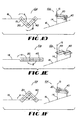
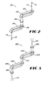
- FIG. 2 shows an embodiment 110 of the invention in which an image 112 may be relayed through the scanner by a single relay lens 160 disposed between the first distal end 124 of the first optical channel 120 and the second proximal end 142 of the second optical channel 140.
- the focal length of the lens 160 is chosen to be one fourth of the optical path length between the foci 113, 114 of the beam 112. This meets a standard 1:1 imaging requirement wherein both the object and the image are located on opposite sides of a converging lens at twice the lens focal length.
- light is uncollimated throughout the entire scanner system.
- FIG. 3 shows an embodiment 210 employing a first lens 262 disposed adjacent the first proximal end 222 of the first optical channel 220 for collimating the beam 212 into the first optical channel 220 and a second lens 266 disposed adjacent the second distal end 244 of the second optical channel 240 for focusing the beam 212.
- This embodiment 210 offers the advantage of decreased optical beam diameter within the scanner. By choosing different focal lengths for the lenses 262, 266 , the image may be magnified or reduced.
- This embodiment provides at least two advantages: first, it promotes the use of low F-number systems (thereby enhancing optical resolution) without requiring the large diameter optical channels; and second, it provides an opportunity to match the F-number of an existing OPU to an optical storage medium for which it was not designed. The latter may be an important consideration where it is desirable to use an OPU designed for a spot size which is different from that of the particular medium being used.
- the beam 212 emerges from an optical pick-up objective as a converging cone of light and comes to a focus at the point where an object would ordinarily be located.
- the illumination continues beyond that point as a diverging cone of light to where it meets the input lens 262 to the scanner.
- the input lens is located one focal length away from the focal plane of the OPU, and it therefore collimates the illumination from the OPU before passing it to the rotating channels 220, 240 .
- the illumination passes through another lens 266 which refocuses the collimated illumination onto the object.
- the reflection from the object is an image of the illuminated data which then propagates backward through the lenses and prisms in exactly the same way as the forward beam.
- FIGS. 4 and 5 show an optical image scanner 310 embodiment of the invention for scanning an optical beam along a linear path 316 on an object 318.
- the scanner 310 has a housing 320 with a top 326 and an opposite bottom 328.
- the housing 320 defines a first cylindrical cavity 322 between the top 326 and the bottom 328.
- a ring gear 330 is disposed within the cylindrical cavity 322 and is affixed to the housing 320
- a device 336 for generating an optical beam 312 along an axis 315 is fixed to the housing 320.
- Such a device 336 could comprise an OPU (which can both generate a beam and sense a beam reflected back from an object), of the type commonly known to the art of CD ROM design.
- a drive disk 340 is disposed within the first cylindrical cavity 322 and defines a second cylindrical cavity 348.
- the drive disk 340 defines a first optical channel 346, that is rotatable about axis 315, in communication with a first proximal opening 352 and a first distal opening 354.
- the drive disk 340 also has a peripheral edge 356.
- a scan disk 360 is disposed within the second cylindrical cavity 348 and defines a second optical channel 366 in communication with a second proximal opening 372 in alignment with the first distal opening 354.
- the scan disk 340 also defines a second distal opening 374 in communication with the second optical channel 366.
- the drive disk 340 and the scan disk 360 are joined by relatively large diameter bearings 382.
- the drive disk 340 is joined to the housing 320 by a bearing 381.
- a ring motor 380 (such as a direct drive DC ring motor) is coupled to the peripheral edge 356 so as to cause the drive disk 340 to rotate.
- other means may be used to rotate the drive disk 340, such as pulleys, drive belts, or gears connected to an external motor (not shown).
- a spur gear 332 is circumferentially affixed to the scan disk 360 and is engaged with the ring gear 330 so that as the ring motor 380 causes the drive disk 340 to rotate, the spur gear 332 is displaced along the ring gear 330, thus causing the scan disk 360 to rotate in a direction opposite the direction that the drive disk 340 is rotating.
- the second distal opening 374 to the second optical channel 366 linearly reciprocates, thereby causing the beam 312 to scan along the linear path 316 on the object 318.
- the beam-generating device 336 causes the beam 312 to propagate along a first direction into the first proximal opening 352
- a first mirror 344 or other beam-diverting device, as is known to the art, directs the beam 312 along a second direction, on a primary plane substantially perpendicular to the first direction, from the first proximal opening 352 into the first optical channel 346.
- a second mirror 342 (or other device) directs the beam 312 along a third direction, substantially parallel to the first direction, from the first optical channel 346 out of the first distal opening 354 and into the second proximal opening 372.
- a third mirror 364 (or other device) directs the beam 312 along a fourth direction, on a secondary plane substantially parallel to the primary plane, from the second proximal opening 372 into the second optical channel 366 and a fourth mirror 362 (or other device) directs the beam 312 along a fifth direction, substantially parallel to the first direction, from the second optical channel 366 out of the second distal opening 374 toward the linear path 316.
- the mirrors 342, 344, 362 and 364 are disposed so as to cause the beam 312 to change direction by 90 degrees.
- the second optical channel 366 must be positioned in such a way that the third mirror 364 is aligned with the second mirror 342 of the first optical channel 346 and it must rotate in a plane substantially parallel to the plane of rotation of the first optical channel 346.
- the drive disk 340 and the scan disk 360 must be carefully balanced to avoid undesirable vibration while rotating.
- Counter rotation in some applications, may be achieved by maintaining a roller in non-slipping contact with rings (not shown) having the same function and dimensions as the gears described above. To operate properly, a means must be provided which prevents slipping between the contacting surfaces. Another method of achieving the required counter-rotation is to drive each disk with separate synchronous motors. The motor rotation rates would be controlled so that each motor drives its associated disk at exactly the same speed, but in opposite direction.
- Another approach to causing counter-rotation of the optical channels includes mechanically constraining the output from the joined channels to follow a straight line. This may be accomplished by attaching the end of the second optical channel to a sliding mechanism (not shown) which is constrained to move within a straight slot, along a rail, or a similar device.
- the first optical channel is rotated uniformly as described above, and as a result of the mechanical constraint, the second optical channel is forced to move in a way which exactly replicates the rotation previously discussed. In this way the desired linear motion is strictly enforced within the limits imposed by the elasticity, fit, and precision of the components.
- the rotational forces existing in the system are such that at the center of scan (rotational angle of 90 degrees), no force exists at the output of the second optical channel, and the system relies solely on the inertia of the second optical channel (developed during the earlier portion of the scan) to carry it through this singular point.
- other means may be employed to carry through the singular point.
- this embodiment It is possible under certain conditions for this embodiment to lock up, or fail to follow a straight line. This may occur if the mechanism attempts to start with the two optical channels aligned exactly anti-parallel (with the output of the second periscope at the center of scan). In this case the output of the second optical channel simply rotates about the input axis to the first optical channel, and the scan degenerates from a straight line to a single point at the center of the data track. This condition may be prevented by controlling the optical channels so that they always stop with the optical channels in an orientation other than anti-parallel, or by providing a bias force by some other means such as a spring, or other element, one end of which is attached to the end of the second optical channel and the other end attached to the end of the slider tracks.
- some other means such as a spring, or other element
- the invention could also be applied to many applications, such as image scanning where an image (e.g., photograph, painting, photographic negative or transparency, radiograph, written document, etc .) is scanned in raster fashion for the purpose of converting a two-dimensional representation of an object to a one-dimensional representation as occurs with electronic information transmission (e . g . television, facsimile)
- image scanning where an image (e.g., photograph, painting, photographic negative or transparency, radiograph, written document, etc .) is scanned in raster fashion for the purpose of converting a two-dimensional representation of an object to a one-dimensional representation as occurs with electronic information transmission ( e . g . television, facsimile)
- the invention may also be used when a serial data stream representing an object is transformed into a two-dimensional representation of the object by raster scanning ( e . g ., for use in a laser printer).
- the embodiments described herein employ an optical beam, the invention contemplates and anticipates embodiments wherein
Landscapes
- Physics & Mathematics (AREA)
- Engineering & Computer Science (AREA)
- Electromagnetism (AREA)
- General Physics & Mathematics (AREA)
- Artificial Intelligence (AREA)
- Toxicology (AREA)
- General Health & Medical Sciences (AREA)
- Computer Vision & Pattern Recognition (AREA)
- Health & Medical Sciences (AREA)
- Theoretical Computer Science (AREA)
- Optics & Photonics (AREA)
- Mechanical Optical Scanning Systems (AREA)
- Microscoopes, Condenser (AREA)
- Ultra Sonic Daignosis Equipment (AREA)
- Vehicle Body Suspensions (AREA)
Claims (20)
- Appareil (10, 110, 210, 310) pour balayer un faisceau (12, 112, 212, 312) émis à partir d'un emplacement fixe, ledit appareil comprenant :moyennant quoi, lorsque le premier canal tourne dans la direction (A) et le second canal tourne dans la direction (B), la seconde extrémité distale du second canal a un mouvement de va-et-vient, amenant ainsi le faisceau (12, 112, 212, 312) à balayer l'objet le long d'une trajectoire.a. un premier canal (26, 120, 220, 346) ayant une première extrémité proximale (22) et du côté opposé une première extrémité distale (24), la première extrémité proximale étant en communication avec le faisceau (12, 112, 212, 312), la première extrémité proximale pouvant tourner par pivotement autour d'un premier axe de rotation contigu à l'emplacement fixe ;b. un second canal (46, 140, 240, 366) ayant une seconde extrémité proximale (42) et du côté opposé une seconde extrémité distale (44), la seconde extrémité proximale (42) étant en communication avec la première extrémité distale du premier canal (26, 120, 220, 346), la seconde extrémité proximale pouvant tourner par pivotement autour d'un second axe de rotation décalé par rapport au premier axe, ledit second axe de rotation étant contigu à la première extrémité distale du premier canal ;c. des moyens (380, 340) pour faire tourner le premier canal (26, 120, 220, 346) autour du premier axe dans une première direction (A) ;d. des moyens (380, 332, 330) pour faire tourner le second canal (46, 140, 240, 366) autour du second axe dans une deuxième direction (B) opposée à la première direction ; ete. des moyens (342, 344, 362, 364) pour faire entrer le faisceau dans le premier canal, lui faire traverser le second canal et le faire sortir de la seconde extrémité distale du second canal pour le diriger vers un objet
- Appareil selon la revendication 1, comprenant en outre des moyens (336) pour produire le faisceau.
- Appareil selon la revendication 2, dans lequel les moyens (336) de production du faisceau comprennent une unité de captage optique.
- Appareil selon la revendication 1, dans lequel le faisceau (12, 112, 212, 312) est un faisceau optique.
- Appareil selon la revendication 1, dans lequel la seconde extrémité distale (44) du second canal (46) a un mouvement de va-et-vient linéaire.
- Appareil selon la revendication 1, comprenant en outre des moyens (336) pour détecter une partie du faisceau réfléchie par l'objet.
- Appareil selon la revendication 1, dans lequel le premier canal (26) a une première longueur et le second canal (46) a une seconde longueur et dans lequel la première longueur est sensiblement égale à la seconde longueur.
- Appareil selon la revendication 1, dans lequel le premier canal (26) a une première vitesse de rotation et le second canal (46) a une seconde vitesse de rotation et dans lequel l'ordre de grandeur de la première vitesse de rotation est sensiblement égal à l'ordre de grandeur de la seconde vitesse de rotation.
- Appareil selon la revendication 1, comprenant en outre :a. un boítier (320) ayant un dessus et à l'opposé un fond, le boítier délimitant une première cavité cylindrique (322) entre le dessus et le fond ;b. un engrenage annulaire (330) disposé à l'intérieur de la cavité cylindrique et fixé au boítier ;c. un disque d'entraínement (340), dans lequel est encastré le premier canal (346), disposé à l'intérieur de la première cavité cylindrique (322) et délimitant une seconde cavité cylindrique (348), le disque d'entraínement pouvant tourner autour du premier axe de rotation ;d. un disque de balayage (360), dans lequel est encastré le second canal (366), disposé à l'intérieur de la seconde cavité cylindrique (348), le disque de balayage pouvant tourner autour du second axe de rotation ; ete. un pignon droit (332) fixé au disque de balayage (360) et en prise avec l'engrenage annulaire (330) dans lequel les moyens de rotation du premier canal font tourner le disque d'entraínement (340) dans la première direction, de manière à faire que le pignon droit (332) se déplace le long de l'engrenage annulaire (330), faisant ainsi tourner le disque de balayage dans la deuxième direction.
- Appareil selon la revendication 9, dans lequel le disque d'entraínement (340) a un bord périphérique (356) et les premiers moyens de rotation comprennent un moteur annulaire (380) accouplé au bord périphérique.
- Appareil selon la revendication 10, comprenant en outre des moyens (336) de production d'un faisceau optique ; et
la seconde extrémité distale du second canal (366) ayant un mouvement de va-et-vient linéaire, amenant ainsi le faisceau à balayer l'objet le long d'une trajectoire linéaire ;
ledit premier canal (346) ayant une première longueur et ledit second canal (366) ayant une seconde longueur et dans lequel la première longueur est sensiblement égale à la seconde longueur ; et
ledit premier canal (346) tournant à une première vitesse de rotation et ledit second canal (366) tournant à une seconde vitesse de rotation sensiblement égale à la première vitesse de rotation. - Appareil selon la revendication 11, comprenant en outre des moyens (336) de détection d'une partie du faisceau réfléchie par la trajectoire linéaire.
- Appareil selon la revendication 11, dans lequel les moyens de production du faisceau optique comprennent une unité de captage optique.
- Appareil selon la revendication 10 ou 11, dans lequel le moteur annulaire (380) est un moteur annulaire à courant continu en prise directe.
- Appareil selon la revendication 1 ou 11, dans lequel le faisceau (312) se propage dans une première direction à partir de l'emplacement fixe vers la première extrémité proximale du premier canal et dans lequel les moyens de couplage comprennent :a. des moyens (344) pour diriger le faisceau dans une deuxième direction dans un plan primaire sensiblement perpendiculaire à la première direction et le faire entrer dans le premier canal (346) par la première extrémité proximale du premier canal ;b. des moyens (342) pour diriger le faisceau dans une troisième direction, sensiblement parallèle à la première direction, hors de la première extrémité distale du premier canal (346) vers la seconde extrémité proximale du second canal (366) ;c. des moyens (364) pour diriger le faisceau dans une quatrième direction dans un plan secondaire sensiblement parallèle au plan primaire et le faire entrer dans le second canal (366) par la seconde extrémité proximale du second canal ; etd. des moyens (362) pour diriger le faisceau dans une cinquième direction, sensiblement parallèle à la première direction, hors de la seconde extrémité distale du second canal (366) vers l'objet.
- Appareil selon la revendication 15, dans lequel chacun des moyens de direction (342, 344, 362, 364) comprend un miroir.
- Appareil selon la revendication 16, dans lequel on dispose chaque miroir (342, 344, 362, 364) pour qu'il soit attenant à chaque extrémité du premier canal (346) et à chaque extrémité du second canal (366) et fasse avec la première direction un angle tel qu'il amène le faisceau à changer de direction à 90 degrés.
- Appareil selon la revendication 15, comprenant en outre :a. une première lentille (262) disposée contiguë à la première extrémité proximale (222) du premier canal (220) pour collimater le faisceau dans le premier canal ; etb. une seconde lentille (266) disposée contiguë à la seconde extrémité distale (244) du second canal (240) pour concentrer le faisceau sur l'objet.
- Appareil selon la revendication 15, comprenant en outre au moins une lentille relais (160) disposée entre la première extrémité distale (124) du premier canal (120) et la seconde extrémité proximale (142) du second canal (140).
- Procédé de balayage d'un faisceau optique (12) le long d'une trajectoire linéaire, comprenant les étapes suivantes :afin que, lorsque le premier canal optique tourne dans la direction (A) et le second canal optique tourne dans la direction (B), le faisceau a un mouvement de va-et-vient linéaire, amenant ainsi le faisceau à balayer un objet le long de la trajectoire linéaire.a. produire en continu le faisceau optique à partir d'un emplacement fixe et diriger le faisceau vers une première extrémité proximale (22) du premier canal optique (26) ;b. rediriger le faisceau à travers le premier canal optique, qui a aussi du côté opposé une première extrémité distale (24), afin que le faisceau se propage de la première extrémité proximale du premier canal optique vers la première extrémité distale du premier canal optique ;c. rediriger le faisceau de la première extrémité distale du premier canal optique vers un second canal optique (46), qui a une seconde extrémité proximale (42) attenante à la première extrémité distale du premier canal optique et du côté opposé une seconde extrémité distale (44), afin que le faisceau se propage de la seconde extrémité proximale du second canal optique vers la seconde extrémité distale du second canal optique ;d. faire tourner le premier canal optique (26) autour de la première extrémité proximale du premier canal optique dans une première direction dans un plan primaire ;e. faire tourner le second canal optique (46) autour de la seconde extrémité proximale du second canal optique dans une seconde direction opposée à ma première direction dans un plan secondaire parallèle au plan primaire ; etf. rediriger le faisceau de la seconde extrémité distale du second canal optique vers la trajectoire linéaire ;
Applications Claiming Priority (3)
| Application Number | Priority Date | Filing Date | Title |
|---|---|---|---|
| US08/760,072 US5914479A (en) | 1996-09-20 | 1996-12-04 | Counter-rotating scanner |
| US760072 | 1996-12-04 | ||
| PCT/US1997/018126 WO1998025224A1 (fr) | 1996-12-04 | 1997-10-06 | Lecteur optique a rotation inverse |
Publications (3)
| Publication Number | Publication Date |
|---|---|
| EP1027678A1 EP1027678A1 (fr) | 2000-08-16 |
| EP1027678A4 EP1027678A4 (fr) | 2001-03-14 |
| EP1027678B1 true EP1027678B1 (fr) | 2004-08-04 |
Family
ID=25058008
Family Applications (1)
| Application Number | Title | Priority Date | Filing Date |
|---|---|---|---|
| EP97910832A Expired - Lifetime EP1027678B1 (fr) | 1996-12-04 | 1997-10-06 | Lecteur optique a rotation inverse |
Country Status (13)
| Country | Link |
|---|---|
| US (1) | US5914479A (fr) |
| EP (1) | EP1027678B1 (fr) |
| JP (1) | JP2001505321A (fr) |
| KR (1) | KR20000069320A (fr) |
| CN (1) | CN1245573A (fr) |
| AT (1) | ATE272868T1 (fr) |
| AU (1) | AU732590B2 (fr) |
| CA (1) | CA2273919C (fr) |
| DE (1) | DE69730169T2 (fr) |
| IL (1) | IL130241A (fr) |
| NZ (1) | NZ336405A (fr) |
| RU (1) | RU2190878C2 (fr) |
| WO (1) | WO1998025224A1 (fr) |
Families Citing this family (10)
| Publication number | Priority date | Publication date | Assignee | Title |
|---|---|---|---|---|
| DE19956439A1 (de) * | 1999-11-24 | 2001-05-31 | Leica Microsystems | Vorrichtung zur Strahlablenkung |
| US7014113B1 (en) * | 2002-08-19 | 2006-03-21 | The Code Corporation | Versatile graphical code reader for reading different types of graphical codes |
| EP2068549A3 (fr) * | 2007-11-28 | 2012-12-26 | Siemens Aktiengesellschaft | Procédé et agencement destinés au balayage en fonction du lieu et du temps de corps rotatif tournant à vitesse variable |
| EP3861366B1 (fr) | 2018-10-02 | 2022-09-28 | Blackmore Sensors & Analytics, LLC | Procédé et système d'optimisation de balayage de lidar cohérent |
| CN112532815B (zh) * | 2019-09-18 | 2022-04-26 | 宁波舜宇光电信息有限公司 | 潜望式摄像模组及电子设备 |
| CN112532814B (zh) * | 2019-09-18 | 2022-08-16 | 宁波舜宇光电信息有限公司 | 潜望式摄像模组及电子设备 |
| US12585092B2 (en) | 2019-09-18 | 2026-03-24 | Ningbo Sunny Opotech Co., Ltd | Periscopic camera module and electronic device |
| CN112532813B (zh) * | 2019-09-18 | 2022-08-09 | 宁波舜宇光电信息有限公司 | 潜望式摄像模组及相应的电子设备 |
| EP4030233B1 (fr) | 2019-09-18 | 2025-05-07 | Ningbo Sunny Opotech Co., Ltd. | Module de caméra périscopique et dispositif électronique |
| CN112532816B (zh) * | 2019-09-18 | 2022-05-17 | 宁波舜宇光电信息有限公司 | 潜望式摄像模组及电子设备 |
Family Cites Families (19)
| Publication number | Priority date | Publication date | Assignee | Title |
|---|---|---|---|---|
| JPS5919798B2 (ja) * | 1974-11-01 | 1984-05-08 | 株式会社日立製作所 | レ−ザ加工装置 |
| US4454610A (en) * | 1978-05-19 | 1984-06-12 | Transaction Sciences Corporation | Methods and apparatus for the automatic classification of patterns |
| JPS57207216A (en) * | 1981-06-17 | 1982-12-18 | Mita Ind Co Ltd | Optical deflector |
| JPS61111036U (fr) * | 1984-12-24 | 1986-07-14 | ||
| US4621893A (en) * | 1985-05-17 | 1986-11-11 | The United States Of America As Represented By The Secretary Of The Army | Satellite optical scan device |
| US4923263A (en) * | 1988-09-22 | 1990-05-08 | The United States Of America As Represented By The Secretary Of The Army | Rotating mirror optical scanning device |
| US4967076A (en) * | 1989-12-08 | 1990-10-30 | Ncr Corporation | Optical scanner producing multiple scan patterns |
| US5052800A (en) * | 1990-05-04 | 1991-10-01 | Cubic Corporation | Boresighting method and apparatus |
| US5422471A (en) * | 1991-08-16 | 1995-06-06 | Plesko; George A. | Scanning device for scanning a target, scanning motor for the device and a method of utilization thereof |
| US5149949A (en) * | 1990-12-10 | 1992-09-22 | Ncr Corporation | Optical scanner with counterrotating reflector elements |
| RU2049340C1 (ru) * | 1992-02-13 | 1995-11-27 | Всесоюзный научный центр "ГОИ им.С.И.Вавилова" | Оптическая сканирующая система |
| US5367399A (en) * | 1992-02-13 | 1994-11-22 | Holotek Ltd. | Rotationally symmetric dual reflection optical beam scanner and system using same |
| US5339188A (en) * | 1992-09-16 | 1994-08-16 | Hughes Aircraft Company | Step stare scanning apparatus and method |
| EP0671697A1 (fr) * | 1993-09-21 | 1995-09-13 | Opticon Sensors Europe B.V. | Générateur de trame de balayage hélicoidale |
| JP3279024B2 (ja) * | 1993-10-30 | 2002-04-30 | ソニー株式会社 | 光ピックアップ装置 |
| US5663550A (en) * | 1994-02-09 | 1997-09-02 | Opticon Sensors Europe B.V. | Multiple-directional laser scanners |
| US5574274A (en) * | 1995-02-21 | 1996-11-12 | Microtek International, Inc. | Transmissive/reflective optical scanning apparatus |
| US5559320A (en) * | 1995-05-19 | 1996-09-24 | Microscan Systems Incorporated | Mounting and balancing system for rotating polygon mirror in a bar code scanner |
| US5721585A (en) * | 1996-08-08 | 1998-02-24 | Keast; Jeffrey D. | Digital video panoramic image capture and display system |
-
1996
- 1996-12-04 US US08/760,072 patent/US5914479A/en not_active Expired - Lifetime
-
1997
- 1997-10-06 DE DE69730169T patent/DE69730169T2/de not_active Expired - Lifetime
- 1997-10-06 WO PCT/US1997/018126 patent/WO1998025224A1/fr not_active Ceased
- 1997-10-06 NZ NZ336405A patent/NZ336405A/xx not_active IP Right Cessation
- 1997-10-06 CA CA002273919A patent/CA2273919C/fr not_active Expired - Fee Related
- 1997-10-06 IL IL13024197A patent/IL130241A/xx not_active IP Right Cessation
- 1997-10-06 RU RU99114017/09A patent/RU2190878C2/ru not_active IP Right Cessation
- 1997-10-06 KR KR1019997005007A patent/KR20000069320A/ko not_active Ceased
- 1997-10-06 EP EP97910832A patent/EP1027678B1/fr not_active Expired - Lifetime
- 1997-10-06 JP JP52556298A patent/JP2001505321A/ja not_active Ceased
- 1997-10-06 CN CN97181666A patent/CN1245573A/zh active Pending
- 1997-10-06 AU AU48109/97A patent/AU732590B2/en not_active Ceased
- 1997-10-06 AT AT97910832T patent/ATE272868T1/de not_active IP Right Cessation
Also Published As
| Publication number | Publication date |
|---|---|
| DE69730169T2 (de) | 2005-10-13 |
| JP2001505321A (ja) | 2001-04-17 |
| KR20000069320A (ko) | 2000-11-25 |
| ATE272868T1 (de) | 2004-08-15 |
| CA2273919C (fr) | 2006-08-01 |
| AU4810997A (en) | 1998-06-29 |
| NZ336405A (en) | 2000-03-27 |
| AU732590B2 (en) | 2001-04-26 |
| US5914479A (en) | 1999-06-22 |
| DE69730169D1 (de) | 2004-09-09 |
| EP1027678A4 (fr) | 2001-03-14 |
| IL130241A (en) | 2003-04-10 |
| RU2190878C2 (ru) | 2002-10-10 |
| CN1245573A (zh) | 2000-02-23 |
| WO1998025224A1 (fr) | 1998-06-11 |
| IL130241A0 (en) | 2000-06-01 |
| CA2273919A1 (fr) | 1998-06-11 |
| EP1027678A1 (fr) | 2000-08-16 |
Similar Documents
| Publication | Publication Date | Title |
|---|---|---|
| US4606601A (en) | Single facet wobble free scanner | |
| US4475787A (en) | Single facet wobble free scanner | |
| US5526167A (en) | Scanning device | |
| EP1027678B1 (fr) | Lecteur optique a rotation inverse | |
| US4284994A (en) | Laser beam recorder | |
| US5818507A (en) | Method and apparatus for controlling the modulation of light beams in a rotating polygon type image forming apparatus | |
| US5218595A (en) | Device for reading oblong segments of an advancing storage medium | |
| US3790246A (en) | X-y optical scanning system | |
| JPH03116112A (ja) | 走査式光学装置 | |
| US5272325A (en) | Scanning device for symbol codes | |
| US4337994A (en) | Linear beam scanning apparatus especially suitable for recording data on light sensitive film | |
| US5365259A (en) | Scanning optical device | |
| JP3271995B2 (ja) | 光学装置 | |
| GB2264182A (en) | Optical beam scanners and systems using same | |
| EP0420198B1 (fr) | Appareil d'analyse à faisceau et appareil pour écrire de l'information d'images | |
| JPS60233616A (ja) | 光学走査装置 | |
| US4058834A (en) | System for making a light beam scan a flat carrier with autofocusing | |
| JPH03179420A (ja) | 光学装置 | |
| HK1026043A (en) | Counter-rotating scanner | |
| JP3215760B2 (ja) | 光記録再生装置 | |
| JPH03179421A (ja) | 光学装置 | |
| US5040861A (en) | Optical scanner | |
| SU1481702A1 (ru) | Сканирующее устройство | |
| JP3507088B2 (ja) | 光走査装置 | |
| Fikes et al. | Rectilinear scanner utilizing uniformly rotating components |
Legal Events
| Date | Code | Title | Description |
|---|---|---|---|
| PUAI | Public reference made under article 153(3) epc to a published international application that has entered the european phase |
Free format text: ORIGINAL CODE: 0009012 |
|
| 17P | Request for examination filed |
Effective date: 19990630 |
|
| AK | Designated contracting states |
Kind code of ref document: A1 Designated state(s): AT BE CH DE DK ES FI FR GB GR IE IT LI LU MC NL PT SE |
|
| AX | Request for extension of the european patent |
Free format text: LT PAYMENT 19990630 |
|
| A4 | Supplementary search report drawn up and despatched |
Effective date: 20010129 |
|
| AK | Designated contracting states |
Kind code of ref document: A4 Designated state(s): AT BE CH DE DK ES FI FR GB GR IE IT LI LU MC NL PT SE |
|
| RIC1 | Information provided on ipc code assigned before grant |
Free format text: 7G 06K 7/10 A, 7G 11B 7/00 B, 7G 11B 7/135 B, 7G 02B 26/10 B |
|
| 17Q | First examination report despatched |
Effective date: 20030428 |
|
| GRAP | Despatch of communication of intention to grant a patent |
Free format text: ORIGINAL CODE: EPIDOSNIGR1 |
|
| GRAS | Grant fee paid |
Free format text: ORIGINAL CODE: EPIDOSNIGR3 |
|
| GRAA | (expected) grant |
Free format text: ORIGINAL CODE: 0009210 |
|
| AK | Designated contracting states |
Kind code of ref document: B1 Designated state(s): AT BE CH DE DK ES FI FR GB GR IE IT LI LU MC NL PT SE |
|
| AX | Request for extension of the european patent |
Extension state: LT |
|
| PG25 | Lapsed in a contracting state [announced via postgrant information from national office to epo] |
Ref country code: NL Free format text: LAPSE BECAUSE OF FAILURE TO SUBMIT A TRANSLATION OF THE DESCRIPTION OR TO PAY THE FEE WITHIN THE PRESCRIBED TIME-LIMIT Effective date: 20040804 Ref country code: LI Free format text: LAPSE BECAUSE OF FAILURE TO SUBMIT A TRANSLATION OF THE DESCRIPTION OR TO PAY THE FEE WITHIN THE PRESCRIBED TIME-LIMIT Effective date: 20040804 Ref country code: FI Free format text: LAPSE BECAUSE OF FAILURE TO SUBMIT A TRANSLATION OF THE DESCRIPTION OR TO PAY THE FEE WITHIN THE PRESCRIBED TIME-LIMIT Effective date: 20040804 Ref country code: CH Free format text: LAPSE BECAUSE OF FAILURE TO SUBMIT A TRANSLATION OF THE DESCRIPTION OR TO PAY THE FEE WITHIN THE PRESCRIBED TIME-LIMIT Effective date: 20040804 Ref country code: BE Free format text: LAPSE BECAUSE OF FAILURE TO SUBMIT A TRANSLATION OF THE DESCRIPTION OR TO PAY THE FEE WITHIN THE PRESCRIBED TIME-LIMIT Effective date: 20040804 Ref country code: AT Free format text: LAPSE BECAUSE OF FAILURE TO SUBMIT A TRANSLATION OF THE DESCRIPTION OR TO PAY THE FEE WITHIN THE PRESCRIBED TIME-LIMIT Effective date: 20040804 |
|
| REG | Reference to a national code |
Ref country code: GB Ref legal event code: FG4D |
|
| REG | Reference to a national code |
Ref country code: CH Ref legal event code: EP |
|
| RAP2 | Party data changed (patent owner data changed or rights of a patent transferred) |
Owner name: AMERICAN LASER DRIVES CORPORATION |
|
| REG | Reference to a national code |
Ref country code: IE Ref legal event code: FG4D |
|
| REF | Corresponds to: |
Ref document number: 69730169 Country of ref document: DE Date of ref document: 20040909 Kind code of ref document: P |
|
| PG25 | Lapsed in a contracting state [announced via postgrant information from national office to epo] |
Ref country code: LU Free format text: LAPSE BECAUSE OF NON-PAYMENT OF DUE FEES Effective date: 20041006 Ref country code: IE Free format text: LAPSE BECAUSE OF NON-PAYMENT OF DUE FEES Effective date: 20041006 |
|
| PG25 | Lapsed in a contracting state [announced via postgrant information from national office to epo] |
Ref country code: MC Free format text: LAPSE BECAUSE OF NON-PAYMENT OF DUE FEES Effective date: 20041031 |
|
| NLT2 | Nl: modifications (of names), taken from the european patent patent bulletin |
Owner name: AMERICAN LASER DRIVES CORPORATION |
|
| PG25 | Lapsed in a contracting state [announced via postgrant information from national office to epo] |
Ref country code: SE Free format text: LAPSE BECAUSE OF FAILURE TO SUBMIT A TRANSLATION OF THE DESCRIPTION OR TO PAY THE FEE WITHIN THE PRESCRIBED TIME-LIMIT Effective date: 20041104 Ref country code: GR Free format text: LAPSE BECAUSE OF FAILURE TO SUBMIT A TRANSLATION OF THE DESCRIPTION OR TO PAY THE FEE WITHIN THE PRESCRIBED TIME-LIMIT Effective date: 20041104 Ref country code: DK Free format text: LAPSE BECAUSE OF FAILURE TO SUBMIT A TRANSLATION OF THE DESCRIPTION OR TO PAY THE FEE WITHIN THE PRESCRIBED TIME-LIMIT Effective date: 20041104 |
|
| PG25 | Lapsed in a contracting state [announced via postgrant information from national office to epo] |
Ref country code: ES Free format text: LAPSE BECAUSE OF FAILURE TO SUBMIT A TRANSLATION OF THE DESCRIPTION OR TO PAY THE FEE WITHIN THE PRESCRIBED TIME-LIMIT Effective date: 20041115 |
|
| NLV1 | Nl: lapsed or annulled due to failure to fulfill the requirements of art. 29p and 29m of the patents act | ||
| LTIE | Lt: invalidation of european patent or patent extension |
Effective date: 20040804 |
|
| REG | Reference to a national code |
Ref country code: CH Ref legal event code: PL |
|
| ET | Fr: translation filed | ||
| PLBE | No opposition filed within time limit |
Free format text: ORIGINAL CODE: 0009261 |
|
| STAA | Information on the status of an ep patent application or granted ep patent |
Free format text: STATUS: NO OPPOSITION FILED WITHIN TIME LIMIT |
|
| 26N | No opposition filed |
Effective date: 20050506 |
|
| REG | Reference to a national code |
Ref country code: IE Ref legal event code: MM4A |
|
| PG25 | Lapsed in a contracting state [announced via postgrant information from national office to epo] |
Ref country code: PT Free format text: LAPSE BECAUSE OF NON-PAYMENT OF DUE FEES Effective date: 20050104 |
|
| PGFP | Annual fee paid to national office [announced via postgrant information from national office to epo] |
Ref country code: GB Payment date: 20100923 Year of fee payment: 14 |
|
| PGFP | Annual fee paid to national office [announced via postgrant information from national office to epo] |
Ref country code: DE Payment date: 20101029 Year of fee payment: 14 |
|
| PGFP | Annual fee paid to national office [announced via postgrant information from national office to epo] |
Ref country code: IT Payment date: 20101019 Year of fee payment: 14 |
|
| PGFP | Annual fee paid to national office [announced via postgrant information from national office to epo] |
Ref country code: FR Payment date: 20111026 Year of fee payment: 15 |
|
| GBPC | Gb: european patent ceased through non-payment of renewal fee |
Effective date: 20121006 |
|
| REG | Reference to a national code |
Ref country code: FR Ref legal event code: ST Effective date: 20130628 |
|
| PG25 | Lapsed in a contracting state [announced via postgrant information from national office to epo] |
Ref country code: DE Free format text: LAPSE BECAUSE OF NON-PAYMENT OF DUE FEES Effective date: 20130501 Ref country code: GB Free format text: LAPSE BECAUSE OF NON-PAYMENT OF DUE FEES Effective date: 20121006 |
|
| REG | Reference to a national code |
Ref country code: DE Ref legal event code: R119 Ref document number: 69730169 Country of ref document: DE Effective date: 20130501 |
|
| PG25 | Lapsed in a contracting state [announced via postgrant information from national office to epo] |
Ref country code: FR Free format text: LAPSE BECAUSE OF NON-PAYMENT OF DUE FEES Effective date: 20121031 Ref country code: IT Free format text: LAPSE BECAUSE OF NON-PAYMENT OF DUE FEES Effective date: 20121006 |