EP1027761B1 - Anschlussleiste für ein schutzrelais - Google Patents
Anschlussleiste für ein schutzrelais Download PDFInfo
- Publication number
- EP1027761B1 EP1027761B1 EP99927211A EP99927211A EP1027761B1 EP 1027761 B1 EP1027761 B1 EP 1027761B1 EP 99927211 A EP99927211 A EP 99927211A EP 99927211 A EP99927211 A EP 99927211A EP 1027761 B1 EP1027761 B1 EP 1027761B1
- Authority
- EP
- European Patent Office
- Prior art keywords
- terminal block
- tier
- relay
- terminal
- contact
- Prior art date
- Legal status (The legal status is an assumption and is not a legal conclusion. Google has not performed a legal analysis and makes no representation as to the accuracy of the status listed.)
- Expired - Lifetime
Links
- 230000001681 protective effect Effects 0.000 title claims abstract description 25
- 238000000034 method Methods 0.000 claims description 7
- 238000000465 moulding Methods 0.000 claims 1
- 239000004020 conductor Substances 0.000 description 2
- 231100001261 hazardous Toxicity 0.000 description 2
- 239000002991 molded plastic Substances 0.000 description 2
- 229910001369 Brass Inorganic materials 0.000 description 1
- 239000000956 alloy Substances 0.000 description 1
- 229910045601 alloy Inorganic materials 0.000 description 1
- 239000010951 brass Substances 0.000 description 1
- 238000010276 construction Methods 0.000 description 1
- 230000007812 deficiency Effects 0.000 description 1
- 238000012544 monitoring process Methods 0.000 description 1
Images


Classifications
-
- H—ELECTRICITY
- H01—ELECTRIC ELEMENTS
- H01R—ELECTRICALLY-CONDUCTIVE CONNECTIONS; STRUCTURAL ASSOCIATIONS OF A PLURALITY OF MUTUALLY-INSULATED ELECTRICAL CONNECTING ELEMENTS; COUPLING DEVICES; CURRENT COLLECTORS
- H01R13/00—Details of coupling devices of the kinds covered by groups H01R12/70 or H01R24/00 - H01R33/00
- H01R13/40—Securing contact members in or to a base or case; Insulating of contact members
- H01R13/42—Securing in a demountable manner
- H01R13/428—Securing in a demountable manner by resilient locking means on the contact members; by locking means on resilient contact members
-
- H—ELECTRICITY
- H01—ELECTRIC ELEMENTS
- H01R—ELECTRICALLY-CONDUCTIVE CONNECTIONS; STRUCTURAL ASSOCIATIONS OF A PLURALITY OF MUTUALLY-INSULATED ELECTRICAL CONNECTING ELEMENTS; COUPLING DEVICES; CURRENT COLLECTORS
- H01R13/00—Details of coupling devices of the kinds covered by groups H01R12/70 or H01R24/00 - H01R33/00
- H01R13/66—Structural association with built-in electrical component
- H01R13/70—Structural association with built-in electrical component with built-in switch
- H01R13/703—Structural association with built-in electrical component with built-in switch operated by engagement or disengagement of coupling parts, e.g. dual-continuity coupling part
- H01R13/7031—Shorting, shunting or bussing of different terminals interrupted or effected on engagement of coupling part, e.g. for ESD protection, line continuity
-
- H—ELECTRICITY
- H01—ELECTRIC ELEMENTS
- H01R—ELECTRICALLY-CONDUCTIVE CONNECTIONS; STRUCTURAL ASSOCIATIONS OF A PLURALITY OF MUTUALLY-INSULATED ELECTRICAL CONNECTING ELEMENTS; COUPLING DEVICES; CURRENT COLLECTORS
- H01R9/00—Structural associations of a plurality of mutually-insulated electrical connecting elements, e.g. terminal strips or terminal blocks; Terminals or binding posts mounted upon a base or in a case; Bases therefor
- H01R9/22—Bases, e.g. strip, block, panel
- H01R9/24—Terminal blocks
- H01R9/2408—Modular blocks
Definitions
- the present invention relates to protective relays for providing protective control to electrical distribution systems. More particularly, the present invention relates to terminal connections which connect the relay circuitry to the electrical distribution system, i.e. terminal block, a relay having a terminal block and a method for assembling a terminal block for a relay.
- Protective relays for electrical distribution systems provide numerous functions relating to protective control, including over-current and under-voltage protection, and are essential elements of any electrical distribution system.
- Protective relays include internal processing circuitry which monitors the portion of the electrical distribution system with which it is associated (e.g., a feeder line) and provide protection and control functions as necessary.
- Conventional protective relays include digital circuitry in which logic functions determine the operation of the relay, such that the relay will operate to provide protective control under certain specified, potentially hazardous conditions.
- Protective relays must be operatively connected to the electrical distribution system to be monitored. Such connections between the internal circuitry of the protective relay and the electrical distribution system are conventionally established by terminal blocks.
- the terminal blocks when the protective relay is associated with a current transformer, enable the relay to short-circuit the terminals of the transformer.
- connection terminals of conventional terminal blocks are typically fixed in configuration. Terminal blocks providing flexible mounting arrangements would be desirable, though conventional terminal blocks do not adequately provide such a capability.
- terminal blocks do not allow shorting capabilities to be configurable for multiple positions and in any location in the block.
- the present invention overcomes the above-noted deficiencies, and achieves other advantages, by providing for a protective relay terminal block as defined in claim 1, 11 and a method for assembling a terminal block as defined in claim 21.
- An exemplary terminal block includes a plurality of separable, modular tiers.
- Each tier has a first end provided with terminal connections for electrical connection to an electrical distribution system.
- a second end, opposite the first end, is provided with a set of contacts for electrical connection to signal terminals of a module in a protective relay.
- Each tier has a different length between the first and second ends.
- Each tier can be provided with at least one dovetailed alignment element which allows the tier to be slidably engaged with a dovetailed alignment element of an adjacent tier to engage adjacent tiers.
- an exemplary protective relay includes relay processing circuitry for performing protection and control functions in an electrical distribution system, and at least one terminal block.
- Each terminal block has a plurality of separable tiers.
- Each tier has a first end provided with terminal connections for electrical connection to the electrical distribution system, and a second end opposite the first end is provided with a set of contacts for electrical connection to the relay processing circuitry.
- Each of the plurality of tiers has a different length between the first and second ends.
- an exemplary terminal block can optionally include shorting fingers electrically connected to each contact, each shorting finger configured so as to contact a shorting finger associated with an adjacent contact when there is no module connected to the terminal block.
- Each terminal connection can be implemented by a screw which attaches a contact to the terminal block at the first end of its associated tier.
- Each contact preferably extends beyond the second end of its associated tier by a substantially uniform length.
- a terminal block according to the present invention advantageously provides enhanced user accessibility as at least one result of the variable number of modular tiers. Further, the terminal block can be mountable in multiple orientations (e.g., left or right), and can be configured, using appropriate shorting fingers, to provide shorting between any two adjacent terminal connections.
- FIG. 1 shows a relay connection interface 12 including terminal blocks 14 provided with terminal connections 16 for connecting the relay to an electrical distribution system (not shown).
- the interface 12 would typically be provided on a surface of a relay housing.
- the terminal blocks 14 can have three tiers, or levels 14a-c, each tier being provided with terminal connections. Each tier has a different length, such that each row of terminal connections is located a different distance from the surface of the relay housing.
- the present invention increases user accessibility to the terminal connections.
- terminal blocks according to the present invention can be mounted facing in multiple directions (e.g., either left or right). This aspect of the terminal block according to the present invention provides additional mounting flexibility over conventional terminal blocks.
- FIG. 2 is a cross-sectional profile view of an exemplary terminal block according to the present invention.
- the terminal block 14 in this example is comprised of three modular, separable tiers 14a, 14b, and 14c. It will be appreciated that, due to the modularity of the tiers, the number of tiers is easily varied. The construction of the tiers, and their assembly into the terminal block of FIG. 2, will be described in more detail below.
- Each tier includes a molded plastic portion 18, a contact 20, and a terminal connection screw 22.
- the terminal connection screw 22 screws into a mounting hole as shown in FIG. 2 and is mechanically and electrically in contact with the contact 20 at a first end.
- the terminal connection screw 22 provides a terminal connection capable of accepting #8 ring style terminals
- the contact 20, at a second end extends beyond the surface of the terminal block 14 for electrical connection to the internal circuitry 26 of the protective relay.
- each terminal block can optionally be provided with shorting fingers 24.
- the shorting fingers 24 are mechanically and electrically attached to an associated contact 20, and the shorting fingers of different contacts are shaped, mounted, and configured so as to come into contact with one another when the terminal block is not connected to relay monitoring and processing circuitry.
- the shorting fingers are particularly advantageous for use with modular relay circuitry, wherein each relay includes some variable number of modules which can be selectively mounted or removed to vary the functions of the relay. In operation, when a terminal block is not associated with a module, the shorting fingers of adjacent contacts will be in contact with one another to automatically short circuit the adjacent contacts.
- the shorting fingers are separated by a non-conductive element provided on the module to allow each contact 20 to be separately electrically connected to the relay processing circuitry. This function of the shorting fingers prevents the otherwise hazardous condition of "live" contacts, where one or more of the terminal screws 20 are electrically connected to the electrical distribution system, and where the contacts are not connected to any relay circuitry.
- a second function of the shorting fingers is to allow shorting to occur between any two adjacent terminal connections on the block. To implement shorting between two desired terminal connections, shorting fingers are provided between appropriate adjacent signal contacts.
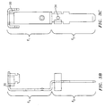
- FIGs. 3A-C show a top view, side view, and front view, respectively, of a contact for use in the terminal block of FIGs. 1-2.
- the contact includes a seat portion 30 at a first end which cooperates with a corresponding seat portion of a tier element to be shown and described later.
- the seat portion 30 includes an aperture 32 through which a connector such as a terminal connection screw can be inserted to mechanically connect the contact to the tier element.
- the contact also includes a contact portion 20 at the opposite end from the seat portion which can be connected to the relay processing circuitry. It will be appreciated that in the example shown in FIGs. 3A-C, the contact portion 20 is configured to connect to a relay processing module, but that the contact portion can be modified as necessary to connect to virtually any type of relay processing circuitry.
- FIGs. 3A-C The contact of FIGs. 3A-C is shown as having a second aperture 34. Such an aperture can be used to attach a shorting finger 24 to the contact, as will be described later in more detail.
- the contact of FIGs. 3A-C includes two portions, a first of length l 1 and a second of length l 2 .
- the length l 1 is selected based on the length of the tier with which the contact will be associated, and the length l 2 is substantially constant such that the contacts 20 of an assembled terminal block extend a substantially uniform and predetermined distance from the terminal block body.
- a three-tier terminal block according to an embodiment of the present invention can include three different types of contacts, having three different l 1 lengths, depending upon the tier in which the contact is to be mounted, but each having the same l 2 lengths.
- the contact of FIGs. 3A-C is preferably formed as a stamping, and preferably can withstand a current of approximately 500 Amps for approximately one second.
- the contact 20 can be made of brass or other suitable conductive material.
- FIGs. 4A-B show a side and rear view, respectively, of a shorting finger 24 according to the present invention.
- the shorting finger 24 includes an aperture 40 (FIG. 4B) which can be aligned with the aperture of the seat portion 30 of an associated contact.
- the shorting finger can be attached to the contact by a rivet or other suitable means.
- the shorting finger 24 is preferably made of a conductive material, such as a BeCu alloy and, according to one example, has a thickness of approximately .016 inches. It will be appreciated that shorting fingers can be provided on all of the contacts, only a portion of the contacts, or none of the contacts in a terminal block, depending upon the particular application.
- FIGs. 5A-C show a top, front, and cross-sectional view, respectively, of a tier element 14 to be assembled with a plurality of contacts, such as is shown in FIGs. 3A-C, to form a tier section of a complete terminal block, such as is shown in FIG. 2.
- the tier element includes seat portions 50, which correspond to the seat portions 30 of the contacts, for seating multiple contacts.
- the tier element also includes mounting portions 52, which are provided with mounting holes 54, which allow the terminal block to be mounted in a secure manner on the protective relay.
- the tier element further includes alignment elements 56 and dovetailed alignment elements 58.
- the dovetailed alignment elements 58 are formed so as to be slidably engageable with corresponding dovetail elements of adjacent tier elements, and the alignment elements 56 facilitate alignment with corresponding alignment elements of adjacent tier elements.
- the alignment elements as shown in FIG. 5B, can extend along substantially the entire front surface, and can include alignment notches N, which cooperate with corresponding alignment notches of alignment elements of neighboring tier elements, to facilitate proper assembly of a multiple tier terminal block.
- FIG. 5C which is a cross-sectional side view along line A-A in FIG. 5B, seat portion 50 at one end of the tier element, and contact cavity 60 at the other end of the tier element.
- An elongated cavity 62 is provided between seat portion 50 and contact cavity 60 to accommodate the contact element shown in FIGs. 3A-C.
- the tier element shown in FIGs. 5A-C is an end tier element, which includes the elements 56 and 58 on only one side. In a multiple tier terminal block, middle tier elements would be provided with alignment elements and dovetailed alignment elements on each side of the tier element.
- a multiple tier terminal block according to the invention can be assembled as follows.
- Tier elements having different lengths are fabricated of e.g., molded plastic.
- each tier element can include a plurality of seat portions each having a first aperture for receiving a terminal connection screw.
- a number of electrically conductive contacts are inserted into the tier elements and press-fit into the tier element to achieve the bent configuration shown in the figures.
- Each contact includes a seat portion which is mounted in the corresponding seat portion of a tier element, and each contact has a midsection length corresponding to the length of the tier element.
- the contact elements are then secured-to the tier element of corresponding length by inserting terminal connection screws through the apertures of the contact seat portions and the tier element seat portions.
- the contact elements can optionally be provided with shorting fingers, according to the particular relay application.
- tiers e.g., three
- the assembled terminal block can then be mounted, in one of multiple orientations (e.g., left or right, vertical or horizontal, etc.), on a protective relay and secured to the protective relay by mounting screws inserted into the mounting holes 54.
- the assembled and mounted terminal block can then be connected to an electrical distribution system via the terminal connection screws, and can be connected to relay processing circuitry via the relay contact portions.
- the terminal block according to the present invention can include a variable number of tiers to enhance accessibility to the terminal connection screws.
- terminal blocks can easily be assembled which provide 8, 16, 24, etc. terminal connections.
Landscapes
- Connections Arranged To Contact A Plurality Of Conductors (AREA)
- Cable Accessories (AREA)
- Connector Housings Or Holding Contact Members (AREA)
- Studio Circuits (AREA)
- Coupling Device And Connection With Printed Circuit (AREA)
- Thermistors And Varistors (AREA)
- Insulating Bodies (AREA)
- Emergency Protection Circuit Devices (AREA)
Claims (25)
- Anschlussblock (14) enthaltend:wobei jede der mehreren Lagen (14a,b,c) eine unterschiedliche Länge zwischen den ersten und zweiten Flächen von den anderen Lagen (14a,b,c) hat.mehrere trennbare, modulare Lagen (14a,b,c), wobei jede Lage (14a,b,c) ein erstes Ende, das mit Anschlussverbindungen (22) für eine elektrische Verbindung mit einem elektrischen Verteilungssystem versehen ist, und ein zweites Ende gegenüber dem ersten Ende aufweist, wobei das zweite Ende mit einem Satz von Kontaktstücken (20) versehen ist für eine elektrische Verbindung mit Signalanschlüssen von einem Modul in einem Schutzrelais,
- Anschlussblock (14) nach Anspruch 1, wobei ferner Kurzschlussfinger (24) vorgesehen sind, die elektrisch mit Kontaktstücken (20) in unterschiedlichen Sätzen verbunden sind, wobei jeder Kurzschlussfinger (24) derart konfiguriert ist, dass er einen Kurzschlussfinger (24) kontaktiert, der einem benachbarten Kontaktstück (20) in einem anderen Satz zugeordnet ist, wenn kein Modul mit dem Anschlussblock verbunden ist.
- Anschlussblock (14) nach Anspruch 1, wobei jede Anschlussverbindung eine Anschlussverbindungsschraube (22) aufweist, die ein Kontaktstück an dem Anschlussblock (14) an dem ersten Ende seiner zugeordneten Lage (14a,b,c) befestigt.
- Anschlussblock (14) nach Anspruch 1, wobei sich jedes Kontaktstück (20) über das zweite Ende seiner zugeordneten Lage (14a,b,c) hinaus erstreckt.
- Anschlussblock (14) nach Anspruch 1, wobei eine variable Anzahl von Lagen (14a,b,c) vorgesehen ist.
- Anschlussblock (14) nach Anspruch 1, wobei drei Lagen (14a,b,c) vorgesehen sind.
- Anschlussblock (14) nach Anspruch 1, wobei der Anschlussblock (14) auf dem Schutzrelais in vielen Orientierungen anbringbar ist.
- Anschlussblock (14) nach Anspruch 1, wobei die Verbindungsanschlüsse (22) und die Kontaktstücke (20) einem Strom von etwa 500A für etwa 1 Sekunde widerstehen können.
- Anschlussblock (14) nach Anspruch 1, wobei ein Kurzschluss zwischen jeweils zwei benachbarten Anschlussverbindungen (22) ausgebildet werden kann.
- Anschlussblock (14) nach Anspruch 1, wobei jede Lage (14a,b,c) mit wenigstens einem schwalbenschwanzförmigen Ausrichtungselement (59) versehen ist, das gestattet, dass die Lage (14a,b,c) verschiebbar mit einem schwalbenschwanzförmigen Ausrichtungselement (59) von einer benachbarten Lage (14a,b,c) in Eingriff gebracht werden kann, um an benachbarten Lagen (14a,b,c) anzugreifen.
- Relais mit einem Anschlussblock (14) enthaltend:wobei jede der mehreren Lagen (14a,b,c) eine andere Länge zwischen den ersten und zweiten Enden als die anderen Lagen (14a,b,c) hat.eine Relais-Bearbeitungsschaltung (26) zum Ausführen von einer oder mehreren Schutz- und Steuerfunktionen in einem elektrischen Verteilungssystem undwenigstens einen Anschlussblock (14), wobei jeder Anschlussblock (14) mehrere trennbare, modulare Lagen (14a,b,c) hat, wobei jede Lage (14a,b,c) ein erstes Ende, das mit Anschlussverbindungen (22) für eine elektrische Verbindung mit einem elektrischen Verteilungssystem versehen ist, und ein zweites Ende gegenüber dem ersten Ende aufweist, wobei das zweite Ende mit einem Satz von Kontaktstücken (20) versehen ist für eine elektrische Verbindung mit der Relais-Bearbeitungsschaltung (26),
- Relais nach Anspruch 11, wobei die Relais-Bearbeitungsschaltung (26) ein oder mehrere auswechselbare Moduln aufweist.
- Relais nach Anspruch 11, wobei ferner Kurzschlussfinger (24) vorgesehen sind, die mit jedem Kontaktstück (20) verbunden sind, wobei jeder Kurzschlussfinger (24) derart konfiguriert ist, dass er einen Kurzschlussfinger (24) kontaktiert, der einem benachbarten Kontaktstück (20) zugeordnet ist, wenn keine Relais-Bearbeitungsschaltung (26) mit den benachbarten Kontaktstücken (20) verbunden ist.
- Relais nach Anspruch 11, wobei jede Anschlussverbindung eine Anschlussverbindungsschraube (22) aufweist, die ein Kontaktstück an dem Anschlussblock (14) an dem ersten Ende seiner zugeordneten Lage (14a,b,c) befestigt.
- Relais nach Anspruch 11, wobei sich jedes Kontaktstück (20) über das zweite Ende seiner zugeordneten Lage (14a,b,c) hinaus erstreckt.
- Relais nach Anspruch 11, wobei jeder Anschlussblock (14) drei Lagen (14a,b,c) hat und jede Lage (14a,b,c) acht Anschlussverbindungen (22) aufweist.
- Relais nach Anspruch 11, wobei jeder Anschlussblock (14) auf dem Schutzrelais in vielen Orientierungen anbringbar ist.
- Relais nach Anspruch 11, wobei die Verbindungsanschlüsse (22) und die Kontaktstücke (20) einem Strom von etwa 500A für etwa 1 Sekunde widerstehen können.
- Relais nach Anspruch 11, wobei ein Kurzschluss zwischen jeweils zwei benachbarten Anschlussverbindungen (22) ausgebildet werden kann.
- Anschlussblock nach Anspruch 1, wobei jede Lage (14a,b,c) mit wenigstens einem schwalbenschwanzförmigen Ausrichtungselement (56) versehen ist, das gestattet, dass die Lage (14a,b,c) verschiebbar mit einem schwalbenschwanzförmigen Ausrichtungselement (58) von einer benachbarten Lage in Eingriff gebracht werden kann, um an benachbarten Lagen (14a,b,c) anzugreifen.
- Verfahren zum Zusammenbauen eines Anschlussblockes (14) für ein Schutzrelais, enthaltend die SchritteAusformen mehrerer Lagenelemente (14a,b,c), die jeweils unterschiedliche Längen von den anderen Lagenelementen (14a,b,c) haben, wobei jedes Lagenelement (14a,b,c) mehrere Sitzabschnitte (50) hat, die jeweils eine erste Öffnung zur Aufnahme einer Anschlussverbindungsschraube (22) haben,Einsetzen mehrerer elektrisch leitfähiger Kontaktstücke (20) mit unterschiedlichen Längen in Lagenelemente (14a,b,c), die unterschiedliche Längen haben, wobei jedes Kontaktstück (20) einen entsprechenden Sitzabschnitt (30) an dem einen Ende und einen Relaiskontaktabschnitt an dem anderen Ende aufweist, wobei der entsprechende Sitzabschnitt (30) eine zweite Öffnung (32) aufweist zum Aufnehmen einer Anschlussverbindungsschraube (22), Presspassen der Kontaktstücke (20) in die Lagenelemente (14a,b,c),Einsetzen einer Anzahl von Anschlussverbindungsschrauben (22) durch die ersten und zweiten Öffnungen, um eine Anschlussblocklage (14a,b,c) zu bilden, die eine Lagenlänge aufweist,Zusammenbauen von zwei oder mehr Anschlussblocklagen (14a,b,c), die jeweils andere Lagenlängen von den anderen Lagen (14a,b,c) haben, um einen Anschlussblock (14) zu formen, der mit einem elektrischen Verteilungssystem über die Anschlussverbindungsschrauben (22) zu verbinden ist und mit der Relais-Bearbeitungsschaltung (26) über die Relais-Kontaktabschnitt zu verbinden ist.
- Verfahren nach Anspruch 21, wobei ferner der Schritt vorgesehen ist, dass ein Kurzschlussfinger (24) an einer Anzahl von Kontaktstücken (20) befestigt wird, wobei jeder Kurzschlussfinger (24) derart konfiguriert ist, dass er in elektrischem Kontakt mit einem Kurzschlussfinger (24) von einem benachbarten Kontaktstück (20) ist, wenn keine Relais-Bearbeitungsschaltung (26) mit den Relais-Kontaktabschnitten verbunden ist.
- Verfahren nach Anspruch 21, wobei ferner der Schritt vorgesehen ist, dass der Anschlussblock (14) in einem Schutzrelais in einer von mehreren Orientierungen angebracht wird.
- Verfahren nach Anspruch 21, wobei der Zusammenbauschritt dadurch ausgeführt wird, dass ein schwalbenschwanzförmiges Ausrichtungselement (56) auf der ersten Lage (14a,b,c) verschiebbar mit einem entsprechenden schwalbenschwanzförmigen Ausrichtungselement (58) auf einer zweiten Lage (14a,b,c) in Eingriff gebracht wird.
- Verfahren nach Anspruch 21, wobei in dem Anschlussblock (14) eine variable Anzahl von Lagenelementen (14a,b,c) vorgesehen wird.
Priority Applications (1)
| Application Number | Priority Date | Filing Date | Title |
|---|---|---|---|
| DK99927211T DK1027761T3 (da) | 1998-06-05 | 1999-06-04 | Klembræt til et beskyttelsesrelæ |
Applications Claiming Priority (3)
| Application Number | Priority Date | Filing Date | Title |
|---|---|---|---|
| US09/090,958 US5999394A (en) | 1998-06-05 | 1998-06-05 | Terminal block for a protective relay |
| PCT/US1999/012459 WO1999063638A1 (en) | 1998-06-05 | 1999-06-04 | Terminal block for a protective relay |
| US90958 | 2002-03-04 |
Publications (3)
| Publication Number | Publication Date |
|---|---|
| EP1027761A1 EP1027761A1 (de) | 2000-08-16 |
| EP1027761A4 EP1027761A4 (de) | 2001-10-10 |
| EP1027761B1 true EP1027761B1 (de) | 2004-09-22 |
Family
ID=22225128
Family Applications (1)
| Application Number | Title | Priority Date | Filing Date |
|---|---|---|---|
| EP99927211A Expired - Lifetime EP1027761B1 (de) | 1998-06-05 | 1999-06-04 | Anschlussleiste für ein schutzrelais |
Country Status (16)
| Country | Link |
|---|---|
| US (1) | US5999394A (de) |
| EP (1) | EP1027761B1 (de) |
| JP (1) | JP2002517892A (de) |
| KR (1) | KR100622743B1 (de) |
| CN (1) | CN1135671C (de) |
| AT (1) | ATE277446T1 (de) |
| AU (1) | AU751160B2 (de) |
| BR (1) | BR9906517A (de) |
| CA (1) | CA2297979C (de) |
| DE (1) | DE69920396T2 (de) |
| DK (1) | DK1027761T3 (de) |
| ES (1) | ES2229717T3 (de) |
| HU (1) | HU224374B1 (de) |
| NO (1) | NO318939B1 (de) |
| PL (1) | PL338519A1 (de) |
| WO (1) | WO1999063638A1 (de) |
Families Citing this family (7)
| Publication number | Priority date | Publication date | Assignee | Title |
|---|---|---|---|---|
| US6459707B1 (en) * | 1998-12-22 | 2002-10-01 | National Instruments Corporation | Relay multiplexer system and method for prevention of shock hazard |
| US6456479B1 (en) * | 2000-02-18 | 2002-09-24 | General Electric Company | Keycode connection arrangement between a processing module and a terminal block |
| GB2425665A (en) * | 2005-04-28 | 2006-11-01 | David Hellier | Layered Terminal Block |
| DE102006019160B4 (de) * | 2006-04-21 | 2008-02-28 | Phoenix Contact Gmbh & Co. Kg | Steckverbinder mit Kurzschlußkontakten |
| ES2739461T3 (es) * | 2008-08-23 | 2020-01-31 | Ostmeier Hubert Dipl Ing | Regleta de terminales como parte de una instalación de alta o media tensión |
| CN103451682B (zh) | 2013-09-16 | 2017-06-06 | 北京科技大学 | 一种含钛可溶阳极熔盐电解提取金属钛的方法 |
| KR102039734B1 (ko) * | 2019-05-07 | 2019-11-26 | 더로드아이앤씨 주식회사 | 모듈형 터미널 블록 및 상기 모듈형 터미널 블록을 포함하는 교통 신호 제어기 |
Family Cites Families (3)
| Publication number | Priority date | Publication date | Assignee | Title |
|---|---|---|---|---|
| JPS4814592B1 (de) * | 1969-05-22 | 1973-05-08 | ||
| US4872855A (en) * | 1988-06-03 | 1989-10-10 | Connectron, Inc. | Adjustable terminal block equipment |
| CH681338A5 (en) * | 1990-09-11 | 1993-02-26 | Comat Ag | Plug socket for relay or electronic circuit module - has termination section with internal contacts and plug-in element fitted to ends of lead wires |
-
1998
- 1998-06-05 US US09/090,958 patent/US5999394A/en not_active Expired - Lifetime
-
1999
- 1999-06-04 ES ES99927211T patent/ES2229717T3/es not_active Expired - Lifetime
- 1999-06-04 JP JP2000552752A patent/JP2002517892A/ja active Pending
- 1999-06-04 DE DE69920396T patent/DE69920396T2/de not_active Expired - Lifetime
- 1999-06-04 CA CA002297979A patent/CA2297979C/en not_active Expired - Fee Related
- 1999-06-04 WO PCT/US1999/012459 patent/WO1999063638A1/en not_active Ceased
- 1999-06-04 HU HU0003557A patent/HU224374B1/hu not_active IP Right Cessation
- 1999-06-04 AU AU44175/99A patent/AU751160B2/en not_active Ceased
- 1999-06-04 AT AT99927211T patent/ATE277446T1/de not_active IP Right Cessation
- 1999-06-04 KR KR1020007001098A patent/KR100622743B1/ko not_active Expired - Fee Related
- 1999-06-04 PL PL99338519A patent/PL338519A1/xx unknown
- 1999-06-04 DK DK99927211T patent/DK1027761T3/da active
- 1999-06-04 CN CNB998009091A patent/CN1135671C/zh not_active Expired - Fee Related
- 1999-06-04 EP EP99927211A patent/EP1027761B1/de not_active Expired - Lifetime
- 1999-06-04 BR BR9906517-7A patent/BR9906517A/pt not_active IP Right Cessation
-
2000
- 2000-02-04 NO NO20000586A patent/NO318939B1/no unknown
Also Published As
| Publication number | Publication date |
|---|---|
| BR9906517A (pt) | 2000-07-25 |
| CA2297979A1 (en) | 1999-12-09 |
| CA2297979C (en) | 2009-12-22 |
| HUP0003557A2 (hu) | 2001-02-28 |
| ATE277446T1 (de) | 2004-10-15 |
| AU751160B2 (en) | 2002-08-08 |
| EP1027761A1 (de) | 2000-08-16 |
| ES2229717T3 (es) | 2005-04-16 |
| EP1027761A4 (de) | 2001-10-10 |
| HU224374B1 (hu) | 2005-08-29 |
| NO20000586D0 (no) | 2000-02-04 |
| JP2002517892A (ja) | 2002-06-18 |
| HUP0003557A3 (en) | 2001-03-28 |
| NO318939B1 (no) | 2005-05-30 |
| CN1135671C (zh) | 2004-01-21 |
| US5999394A (en) | 1999-12-07 |
| PL338519A1 (en) | 2000-11-06 |
| CN1272972A (zh) | 2000-11-08 |
| DE69920396D1 (de) | 2004-10-28 |
| KR20010022510A (ko) | 2001-03-15 |
| WO1999063638A1 (en) | 1999-12-09 |
| DE69920396T2 (de) | 2005-09-29 |
| AU4417599A (en) | 1999-12-20 |
| DK1027761T3 (da) | 2005-01-31 |
| NO20000586L (no) | 2000-03-30 |
| KR100622743B1 (ko) | 2006-09-13 |
Similar Documents
| Publication | Publication Date | Title |
|---|---|---|
| US5086368A (en) | Connector bank with voltage surge protection | |
| EP1680841B1 (de) | Jack-Buchse mit modulärer Montagehülse | |
| US5575690A (en) | Hybrid modular electrical connector system | |
| CA2863676C (en) | Electrical connector with a push-in type contact | |
| US5249978A (en) | High power connector | |
| EP0434964A1 (de) | Bauelementensatz zum gleizeitigen elektrischen Verbinden einer Mehrzahl von modularen Selbstschaltern | |
| US4737113A (en) | Jack assembly having a unitary housing | |
| EP0362943B1 (de) | Verbinder | |
| EP0550854A2 (de) | Elektrischer Verbinder mit Steckererkennungsschalter | |
| EP1027761B1 (de) | Anschlussleiste für ein schutzrelais | |
| US7419384B2 (en) | Plug for connection strips and method for the production thereof | |
| EP1032089A1 (de) | Elektrische Verbinderanordnung | |
| US4136295A (en) | Aircraft brush module | |
| EP1000446B1 (de) | Koaxialverbinder | |
| US7114971B1 (en) | Multi-system plug-in power receptacle for modular power distribution system | |
| US7548412B2 (en) | Switchable fused power distribution block | |
| US5190464A (en) | Shielded electrical connector with contact shunting arrangement | |
| MXPA00001289A (en) | Terminal block for a protective relay | |
| CA2142131A1 (en) | Assembly of multi-terminal telecommunications connectors and terminals | |
| US6238250B1 (en) | In-jack shunt connections and methods therefor | |
| CA2005920C (en) | Terminal block | |
| US6948962B1 (en) | Flexible jumper receptacle | |
| US6456479B1 (en) | Keycode connection arrangement between a processing module and a terminal block | |
| WO2006081424A1 (en) | Loop plug | |
| CA1106011A (en) | Aircraft brush module |
Legal Events
| Date | Code | Title | Description |
|---|---|---|---|
| PUAI | Public reference made under article 153(3) epc to a published international application that has entered the european phase |
Free format text: ORIGINAL CODE: 0009012 |
|
| 17P | Request for examination filed |
Effective date: 20000609 |
|
| AK | Designated contracting states |
Kind code of ref document: A1 Designated state(s): AT BE CH DE DK ES FI FR GB IT LI NL SE |
|
| A4 | Supplementary search report drawn up and despatched |
Effective date: 20010823 |
|
| AK | Designated contracting states |
Kind code of ref document: A4 Designated state(s): AT BE CH DE DK ES FI FR GB IT LI NL SE |
|
| RIC1 | Information provided on ipc code assigned before grant |
Free format text: 7H 02H 9/00 A, 7H 01R 9/24 B, 7H 01R 13/703 B |
|
| 17Q | First examination report despatched |
Effective date: 20030411 |
|
| GRAP | Despatch of communication of intention to grant a patent |
Free format text: ORIGINAL CODE: EPIDOSNIGR1 |
|
| GRAS | Grant fee paid |
Free format text: ORIGINAL CODE: EPIDOSNIGR3 |
|
| GRAA | (expected) grant |
Free format text: ORIGINAL CODE: 0009210 |
|
| AK | Designated contracting states |
Kind code of ref document: B1 Designated state(s): AT BE CH DE DK ES FI FR GB IT LI NL SE |
|
| REG | Reference to a national code |
Ref country code: GB Ref legal event code: FG4D |
|
| REG | Reference to a national code |
Ref country code: CH Ref legal event code: EP |
|
| REF | Corresponds to: |
Ref document number: 69920396 Country of ref document: DE Date of ref document: 20041028 Kind code of ref document: P |
|
| REG | Reference to a national code |
Ref country code: CH Ref legal event code: NV Representative=s name: SERVOPATENT GMBH |
|
| REG | Reference to a national code |
Ref country code: SE Ref legal event code: TRGR |
|
| REG | Reference to a national code |
Ref country code: DK Ref legal event code: T3 |
|
| REG | Reference to a national code |
Ref country code: ES Ref legal event code: FG2A Ref document number: 2229717 Country of ref document: ES Kind code of ref document: T3 |
|
| PLBE | No opposition filed within time limit |
Free format text: ORIGINAL CODE: 0009261 |
|
| STAA | Information on the status of an ep patent application or granted ep patent |
Free format text: STATUS: NO OPPOSITION FILED WITHIN TIME LIMIT |
|
| ET | Fr: translation filed | ||
| 26N | No opposition filed |
Effective date: 20050623 |
|
| PGFP | Annual fee paid to national office [announced via postgrant information from national office to epo] |
Ref country code: AT Payment date: 20070521 Year of fee payment: 9 |
|
| PGFP | Annual fee paid to national office [announced via postgrant information from national office to epo] |
Ref country code: NL Payment date: 20070624 Year of fee payment: 9 |
|
| PGFP | Annual fee paid to national office [announced via postgrant information from national office to epo] |
Ref country code: FI Payment date: 20070628 Year of fee payment: 9 Ref country code: CH Payment date: 20070628 Year of fee payment: 9 |
|
| PGFP | Annual fee paid to national office [announced via postgrant information from national office to epo] |
Ref country code: DK Payment date: 20070629 Year of fee payment: 9 |
|
| PGFP | Annual fee paid to national office [announced via postgrant information from national office to epo] |
Ref country code: SE Payment date: 20070627 Year of fee payment: 9 Ref country code: BE Payment date: 20070716 Year of fee payment: 9 |
|
| REG | Reference to a national code |
Ref country code: CH Ref legal event code: PFA Owner name: GENERAL ELECTRIC COMPANY Free format text: GENERAL ELECTRIC COMPANY#1 RIVER ROAD#SCHENECTADY, NY 12345 (US) -TRANSFER TO- GENERAL ELECTRIC COMPANY#1 RIVER ROAD#SCHENECTADY, NY 12345 (US) |
|
| BERE | Be: lapsed |
Owner name: *GENERAL ELECTRIC CY Effective date: 20080630 |
|
| REG | Reference to a national code |
Ref country code: CH Ref legal event code: PL |
|
| REG | Reference to a national code |
Ref country code: DK Ref legal event code: EBP |
|
| EUG | Se: european patent has lapsed | ||
| PG25 | Lapsed in a contracting state [announced via postgrant information from national office to epo] |
Ref country code: FI Free format text: LAPSE BECAUSE OF NON-PAYMENT OF DUE FEES Effective date: 20080604 |
|
| NLV4 | Nl: lapsed or anulled due to non-payment of the annual fee |
Effective date: 20090101 |
|
| PG25 | Lapsed in a contracting state [announced via postgrant information from national office to epo] |
Ref country code: BE Free format text: LAPSE BECAUSE OF NON-PAYMENT OF DUE FEES Effective date: 20080630 |
|
| PG25 | Lapsed in a contracting state [announced via postgrant information from national office to epo] |
Ref country code: AT Free format text: LAPSE BECAUSE OF NON-PAYMENT OF DUE FEES Effective date: 20080604 |
|
| PG25 | Lapsed in a contracting state [announced via postgrant information from national office to epo] |
Ref country code: NL Free format text: LAPSE BECAUSE OF NON-PAYMENT OF DUE FEES Effective date: 20090101 |
|
| PG25 | Lapsed in a contracting state [announced via postgrant information from national office to epo] |
Ref country code: LI Free format text: LAPSE BECAUSE OF NON-PAYMENT OF DUE FEES Effective date: 20080630 Ref country code: CH Free format text: LAPSE BECAUSE OF NON-PAYMENT OF DUE FEES Effective date: 20080630 |
|
| PG25 | Lapsed in a contracting state [announced via postgrant information from national office to epo] |
Ref country code: DK Free format text: LAPSE BECAUSE OF NON-PAYMENT OF DUE FEES Effective date: 20090106 |
|
| PG25 | Lapsed in a contracting state [announced via postgrant information from national office to epo] |
Ref country code: DK Free format text: LAPSE BECAUSE OF NON-PAYMENT OF DUE FEES Effective date: 20080630 |
|
| PG25 | Lapsed in a contracting state [announced via postgrant information from national office to epo] |
Ref country code: SE Free format text: LAPSE BECAUSE OF NON-PAYMENT OF DUE FEES Effective date: 20080605 |
|
| PGFP | Annual fee paid to national office [announced via postgrant information from national office to epo] |
Ref country code: ES Payment date: 20150626 Year of fee payment: 17 |
|
| PGFP | Annual fee paid to national office [announced via postgrant information from national office to epo] |
Ref country code: IT Payment date: 20150625 Year of fee payment: 17 |
|
| REG | Reference to a national code |
Ref country code: FR Ref legal event code: PLFP Year of fee payment: 18 |
|
| PGFP | Annual fee paid to national office [announced via postgrant information from national office to epo] |
Ref country code: GB Payment date: 20160627 Year of fee payment: 18 |
|
| PGFP | Annual fee paid to national office [announced via postgrant information from national office to epo] |
Ref country code: FR Payment date: 20160628 Year of fee payment: 18 |
|
| PGFP | Annual fee paid to national office [announced via postgrant information from national office to epo] |
Ref country code: DE Payment date: 20160628 Year of fee payment: 18 |
|
| PG25 | Lapsed in a contracting state [announced via postgrant information from national office to epo] |
Ref country code: IT Free format text: LAPSE BECAUSE OF NON-PAYMENT OF DUE FEES Effective date: 20160604 |
|
| REG | Reference to a national code |
Ref country code: DE Ref legal event code: R119 Ref document number: 69920396 Country of ref document: DE |
|
| GBPC | Gb: european patent ceased through non-payment of renewal fee |
Effective date: 20170604 |
|
| REG | Reference to a national code |
Ref country code: FR Ref legal event code: ST Effective date: 20180228 |
|
| PG25 | Lapsed in a contracting state [announced via postgrant information from national office to epo] |
Ref country code: DE Free format text: LAPSE BECAUSE OF NON-PAYMENT OF DUE FEES Effective date: 20180103 Ref country code: GB Free format text: LAPSE BECAUSE OF NON-PAYMENT OF DUE FEES Effective date: 20170604 |
|
| PG25 | Lapsed in a contracting state [announced via postgrant information from national office to epo] |
Ref country code: FR Free format text: LAPSE BECAUSE OF NON-PAYMENT OF DUE FEES Effective date: 20170630 Ref country code: ES Free format text: LAPSE BECAUSE OF NON-PAYMENT OF DUE FEES Effective date: 20160605 |
|
| REG | Reference to a national code |
Ref country code: ES Ref legal event code: FD2A Effective date: 20180626 |