EP1027951B2 - Arc welding monitoring device - Google Patents
Arc welding monitoring device Download PDFInfo
- Publication number
- EP1027951B2 EP1027951B2 EP98936709A EP98936709A EP1027951B2 EP 1027951 B2 EP1027951 B2 EP 1027951B2 EP 98936709 A EP98936709 A EP 98936709A EP 98936709 A EP98936709 A EP 98936709A EP 1027951 B2 EP1027951 B2 EP 1027951B2
- Authority
- EP
- European Patent Office
- Prior art keywords
- welding
- robot
- voltage
- data
- monitoring device
- Prior art date
- Legal status (The legal status is an assumption and is not a legal conclusion. Google has not performed a legal analysis and makes no representation as to the accuracy of the status listed.)
- Expired - Lifetime
Links
Images


Classifications
-
- B—PERFORMING OPERATIONS; TRANSPORTING
- B23—MACHINE TOOLS; METAL-WORKING NOT OTHERWISE PROVIDED FOR
- B23K—SOLDERING OR UNSOLDERING; WELDING; CLADDING OR PLATING BY SOLDERING OR WELDING; CUTTING BY APPLYING HEAT LOCALLY, e.g. FLAME CUTTING; WORKING BY LASER BEAM
- B23K9/00—Arc welding or cutting
- B23K9/095—Monitoring or automatic control of welding parameters
- B23K9/0953—Monitoring or automatic control of welding parameters using computing means
Definitions
- the present invention relates to an arc welding monitoring device which monitors arc welding and controls welding quality.
- an arc welding monitoring device which comprises a means for detecting a welding current or an arc voltage, and A/D converter for converting analog output signals of the detecting means to digital signals in terms of a sampling frequency, a means for setting an operator period and fluctuation pitch to obtain a fluctuation mean, a means for setting a monitoring value to monitor the fluctuation mean value of the welding current or arc voltage, a means for judging welding conditions or welding results by comparing the fluctuation means value of the welding current or arc voltage with monitoring values, and a means for displaying and outputting the judgement results of the judging means.
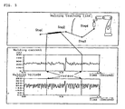
- this drawing is a graph showing changes in a welding current and a welding voltage with respect to welding time.
- Document JP-A-58053374 is regarded to represent the most relevant state of the art and discloses a device to check welding conditions and to improve working efficiency in a welder which operates a robot automatically from stored points to points by making the displaying of the measured values of the welding voltage and current detected with a welding power source possible. Its constitution is as follows: A titled device which is provided with the input part which inputs position data of a robot and the data on welding current and voltage, storage parts of these input data, a display part displaying the data, a central processing part for controlling the input part, storage parts and a display part.
- the device performs automatic welding by storing the position data in points, and the data on the welding current and voltage and operating the robot from these points to point and displays the data corresponding to these points simultaneously on the display part.
- a display control parts which divides the actually measured data on the welding current and voltage and the stored data equally is provided to said device, and the stored data and the actually measured value are displayed on the display part.
- an object of the invention to provide an arc welding monitoring device by which it is possible to easily find the trajectories of a robot, in other words, how detected data such as a welding current and a welding voltage, etc., correspond to welding line information of a welding work.
- a arc welding monitoring device is defined in claim 1.
- FIG. 1 is a general configurational view of a system, wherein 1 is a robot controlling device,. 2 is a welder, 3 is a torch attached to a robot (not illustrated), and 12 is a monitoring device.
- An arc is generated by applying voltage, which is provided by the welder 2, between parent metal 10 and the torch 3, whereby a welding bead is formed by moving the torch 3.
- a current detector 4 detects the welding current
- a voltage detector 5 detects the welding voltage.
- the detected welding current and welding voltage are inputted into low-pass filters 6 and 7, wherein high frequency components (noise) are removed.
- the data are converted to digital values by A/D converts 8 and 9 and are picked up into the robot controlling device 1.
- the picked up welding current and welding voltage are variously operated and processed by a central processing unit (hereinafter called "CPU") 11, whereby the arc state is monitored in compliance with various types of algorithms, and the picked up welding current and welding voltage are adequately stored in a storing portion 14.
- CPU central processing unit
- the trajectory information of the robot is acquired by a locus position detector 13 in the robot controlling device 1, and the information is stored in the storing portion 14.
- a motion simulation of a robot is carried out on the display of the monitoring device 12 based on the robot trajectory information stored in the storing portion 14, and a trajectory of the robot is displayed thereon.
- the welding current and welding voltage stored in the storing portion 14 are displayed on the display of the monitoring device 12, whereby it is possible to not only observe changes in the welding current and welding voltage but also check the movement programs of the robot, whereby it is possible to find a pattern of a welding line of a welding work.
- a robot movement simulation is carried out on the display of the monitoring device 12 based on the robot trajectory information stored in the storing portion 14, whereby the robot trajectory is displayed.
- a mouse may be used as a peripheral input device.
- the contents of the welding current and welding voltage data in a range can be displayed on the display of the monitoring device 12.
- Fig. 4 shows one example of the screen displays at this time.
- the upper stage indicates the trajectories of a robot while the lower stage indicates changes in the welding current and welding voltage.
- the robot moves in the order of step 1, step 2, step 3, step 4, wherein step 1 is the initiating point of welding and step 4 is the terminating point of welding while steps 2 and 3 are points of teaching.
- the range depicted by the thick line between step 1 and step 2 indicates the selected range for indicating waveforms selected by an inputting device such as a mouse, etc., whereby an operator can easily find the contents of the welding current and welding voltage data at the designated points of welding work by only designating a range of trajectories corresponding to the welding work.
- a motion simulation is carried out on the display of the monitoring device 12 based on the robot trajectory information stored in the storing portion 14. And, the welding current and welding voltage stored in the storing portion 14 are concurrently displayed on the display.
- the cursor is displayed on the welding current and welding voltage graph, whereby the data range is designated.
- the trajectory portion corresponding to the range is displayed with, for example, a color different from that outside the range, whereby it is then possible to distinguish to which portion of the trajectories the selected range of the welding current and welding voltage data belong.
- FIG. 5 shows one example of display screens at this time.
- the upper stage indicates trajectories of the robot while the lower stage indicates changes in the welding current and welding voltage.
- the robot moves in the order of step 1, step 2, step 3, and step 4, wherein step 1 is the initiating point of welding and step 4 is the terminating point of welding while steps 2 and 3 are points of teaching.
- the range depicted by the thick line between step 1 and step 2 expresses an area in which the welding current and welding voltage in the range selected by the cursor at the lower stage in FIG. 5 are obtained.
- FIG 2 is a block diagram of an embodiment of the portion for processing judgement of a welding abnormality.
- Judgement of a welding abnormality is carried out by a welding abnormality judging device 22 in the robot controlling device 1.
- the welding abnormality judging device 22 consists of a welding abnormality judging condition sitting device 24, comparator 23, and an output device 25 of welding abnormality judgement results. Still not being part of the invention data acquired by various types of sensors are picked up into a sensor data input portion 21, wherein the picked up data are compared by the comparator 23 with reference values predetermined by the welding abnormality judging condition setting device 24.
- a fifth embodiment that is not part of the invention, it is possible to concurrently display, on the display, information obtained by various types of sensors, such as, for example, a wire feeding speed, gas flow rate, etc., including various types of measured data other than the welding current and welding voltage stored in the storing portion 14.
- the portion which is judged abnormal, of various types of measured data displayed on the display is indicated with a color different from that in a normal case.
- a portion which is judged abnormal is indicated with a color different from that in a normal case, whereby it is possible to easily distinguish to which range of data the portions which are judged abnormal in changes in the patterns of various types of measured data belong, or at which part of the trajectories, that is, the welding work, it is abnormal.
- the present invention relates to an arc welding monitoring device which takes roles of monitoring welding states and controlling the welding quality, in an arc welding robot system.
Landscapes
- Engineering & Computer Science (AREA)
- Physics & Mathematics (AREA)
- Plasma & Fusion (AREA)
- Mechanical Engineering (AREA)
- Theoretical Computer Science (AREA)
- Arc Welding Control (AREA)
- Manipulator (AREA)
- Numerical Control (AREA)
Description
- The present invention relates to an arc welding monitoring device which monitors arc welding and controls welding quality.
- Conventionally, as a device for monitoring arc welding, there has been a welding monitoring device which detects a welding current and a welding voltage during welding, distinguishes whether or not the detected data are within the predetermined range, and issues an alarm when either of the detected data is outside the range. For example, this method is disclosed by
Japanese Patent Publication No. 7-2275 Japanese Patent Publication No. 7-2275 FIG. 3 shows one example of display screens of the detected data at this time, wherein the abscissa indicates a welding current, a welding voltage, and the ordinate indicates a period of time of welding. That is, this drawing is a graph showing changes in a welding current and a welding voltage with respect to welding time. - However, where, in welding made by an arc welding robot, welding conditions are monitored by a prior art welding monitoring device, it is possible to recognize whether or not any welding defect occurred, by acquiring changes in the welding current and welding voltage with respect to the elapse time of welding as shown in
FIG. 3 . However, it is not possible to understand which program of the robot has been used, in other words, which kind of a welding work has been welded. In particular, in a case where a complicated work is welded, by using an arc welding robot, it was difficult to know at which part of the welding work a defect occurred even though a welding defect is detected by the welding monitoring device. To the contrary, in a case where a welding defect is found by observing the welding work, there is a case where it is desired to analyze how the then welding current waveform or welding voltage form are brought about. But, in such a prior art welding monitoring device, it is not clear to which part of the detected data the welding current and welding voltage corresponding to the range selected by a welding work belong. - Document
JP-A-58053374 - It is therefore. an object of the invention to provide an arc welding monitoring device by which it is possible to easily find the trajectories of a robot, in other words, how detected data such as a welding current and a welding voltage, etc., correspond to welding line information of a welding work.
- In order to achieve the above object, a arc welding monitoring device, according to the invention, is defined in
claim 1. - Since it is possible to specify a portion of abnormal or defective welding, it is sufficient to check the portions which are judged abnormal or defective, when conducting a visual defect detection on welding work.
-
-
FIG. 1 is a general configurational view of an arc welding monitoring device that is not part of the invention, -
FIG. 2 is a view showing the outline of an abnormal welding judgement processing portion of an arc welding monitoring device that is not part of the invention, -
FIG. 3 is a description of a screen display of a welding current and a welding voltage, which are displayed on a monitor screen, in a prior art arc welding monitoring device, -
FIG. 4 is an example of a screen display of the welding current, welding voltage and trajectories, which are displayed on a monitor screen by an arc welding monitoring device that is not part of the invention, and -
FIG. 5 is another example of a screen display of the welding current, welding voltage and trajectories, which are displayed on a monitor screen by an arc welding monitoring device that is not part of the invention. - Hereinafter, a description is given of an arc welding monitoring device that is not part of the invention.
FIG. 1 is a general configurational view of a system, wherein 1 is a robot controlling device,. 2 is a welder, 3 is a torch attached to a robot (not illustrated), and 12 is a monitoring device. - Hereinafter, a description is given of an operation flow of welding execution and detection of a welding current and a welding voltage. An arc is generated by applying voltage, which is provided by the
welder 2, betweenparent metal 10 and thetorch 3, whereby a welding bead is formed by moving thetorch 3. At this time, acurrent detector 4 detects the welding current, and avoltage detector 5 detects the welding voltage. The detected welding current and welding voltage are inputted into low-pass filters D converts robot controlling device 1. The picked up welding current and welding voltage are variously operated and processed by a central processing unit (hereinafter called "CPU") 11, whereby the arc state is monitored in compliance with various types of algorithms, and the picked up welding current and welding voltage are adequately stored in astoring portion 14. The trajectory information of the robot is acquired by a locus position detector 13 in therobot controlling device 1, and the information is stored in the storingportion 14. - In a first embodiment that is not part of the invention, a motion simulation of a robot is carried out on the display of the
monitoring device 12 based on the robot trajectory information stored in the storingportion 14, and a trajectory of the robot is displayed thereon. Simultaneously, the welding current and welding voltage stored in the storingportion 14 are displayed on the display of themonitoring device 12, whereby it is possible to not only observe changes in the welding current and welding voltage but also check the movement programs of the robot, whereby it is possible to find a pattern of a welding line of a welding work. - In a second embodiment of an arc welding monitoring device that is not part of the invention, a robot movement simulation is carried out on the display of the
monitoring device 12 based on the robot trajectory information stored in the storingportion 14, whereby the robot trajectory is displayed. As a method for setting a range of screen displays of the welding current and welding voltage stored in the storingportion 14 on the display when the trajectory of a robot is displayed, for example, a mouse may be used as a peripheral input device. By setting a range of trajectories for which change in the detected data are required to be checked, using a mouse, the contents of the welding current and welding voltage data in a range can be displayed on the display of themonitoring device 12.Fig. 4 shows one example of the screen displays at this time. In the drawing, the upper stage indicates the trajectories of a robot while the lower stage indicates changes in the welding current and welding voltage. In the same drawing, the robot moves in the order ofstep 1,step 2,step 3,step 4, whereinstep 1 is the initiating point of welding andstep 4 is the terminating point of welding whilesteps step 1 andstep 2 indicates the selected range for indicating waveforms selected by an inputting device such as a mouse, etc., whereby an operator can easily find the contents of the welding current and welding voltage data at the designated points of welding work by only designating a range of trajectories corresponding to the welding work. - In a third embodiment of an arc welding monitoring device that is not part of the invention, as in the second embodiment, a motion simulation is carried out on the display of the
monitoring device 12 based on the robot trajectory information stored in the storingportion 14. And, the welding current and welding voltage stored in the storingportion 14 are concurrently displayed on the display. There is a case where it is necessary to check to which part of trajectories a certain range of data of the welding current and welding voltage displayed on the display corresponds. In such a case, for example, the cursor is displayed on the welding current and welding voltage graph, whereby the data range is designated. The trajectory portion corresponding to the range is displayed with, for example, a color different from that outside the range, whereby it is then possible to distinguish to which portion of the trajectories the selected range of the welding current and welding voltage data belong.FIG. 5 shows one example of display screens at this time. In the same drawing, the upper stage indicates trajectories of the robot while the lower stage indicates changes in the welding current and welding voltage. In the same drawing, the robot moves in the order ofstep 1,step 2,step 3, andstep 4, whereinstep 1 is the initiating point of welding andstep 4 is the terminating point of welding whilesteps step 1 andstep 2 expresses an area in which the welding current and welding voltage in the range selected by the cursor at the lower stage inFIG. 5 are obtained. Thereby, where an extraordinary point is found in changes in the patterns of the welding current, welding voltage data, etc., it is possible to easily distinguish to which part of the trajectories or the welding work the data correspond. - In a fourth embodiment that is not part of the invention, welding state monitoring can be carried out by further adding a portion for processing judgement of a welding abnormality to the second and third embodiments.
FIG 2 is a block diagram of an embodiment of the portion for processing judgement of a welding abnormality. Judgement of a welding abnormality is carried out by a weldingabnormality judging device 22 in therobot controlling device 1. The weldingabnormality judging device 22 consists of a welding abnormality judgingcondition sitting device 24,comparator 23, and anoutput device 25 of welding abnormality judgement results. Still not being part of the invention data acquired by various types of sensors are picked up into a sensor data input portion 21, wherein the picked up data are compared by thecomparator 23 with reference values predetermined by the welding abnormality judgingcondition setting device 24. Unless the detected data are within the abovementioned reference values, information on occurrence of a welding abnormality is stored in the storingportion 14 by theoutput device 25 of welding abnormality judgement results. Further, simultaneously, an abnormality detecting signal is outputted to a peripheral device by aperipheral alarm device 26, in order to notify that an abnormality has occurred. In addition, as an algorithm for judging a welding abnormality, the number of times of shortcircuiting, mean welding current value, mean welding voltage value, etc., may be utilized. With respect to displaying of the measured data by themonitoring device 12, a motion simulation is carried out on the display on the basis of the robot trajectory information stored in the storingportion 14 as in the second and third embodiments. - In a fifth embodiment that is not part of the invention, it is possible to concurrently display, on the display, information obtained by various types of sensors, such as, for example, a wire feeding speed, gas flow rate, etc., including various types of measured data other than the welding current and welding voltage stored in the storing
portion 14. The portion which is judged abnormal, of various types of measured data displayed on the display is indicated with a color different from that in a normal case. Further and in accordance with the invention with respect to the trajectories, a portion which is judged abnormal is indicated with a color different from that in a normal case, whereby it is possible to easily distinguish to which range of data the portions which are judged abnormal in changes in the patterns of various types of measured data belong, or at which part of the trajectories, that is, the welding work, it is abnormal. - The present invention relates to an arc welding monitoring device which takes roles of monitoring welding states and controlling the welding quality, in an arc welding robot system.
Claims (2)
- An arc welding monitoring device for an arc welding robot controlling apparatus, comprising:a means for detecting electric signals, which detects either a welding current or a welding voltage; anda means for storing trajectories of a robot, wherein it further comprisesa means for storing said detected welding electric signals;a means for simultaneously displaying graphically by diagrams on a screen display, trajectories of a robot, which are stored by said storing means, and at least a range of corresponding welding current or corresponding welding voltage detected by said detecting means;means for setting said range to be displayed, wherein setting is carried out by designating the portion of the trajectories of a robot, which is displayed on said screen display; anda means for setting judgment conditions of a welding abnormality, and a comparator for comparing the conditions established by said setting means with said detected data, and when any abnormality is found to have been generated by monitoring said detected date and judging a welding abnormality, the range of data in which a welding abnormality occurred is displayed on the trajectory with a color different from that of the other remaining range.
- An arc welding monitoring device as set forth in claim 1, wherein said data storing means stores data acquired by various types of sensors in addition to the welding current and welding voltage.
Applications Claiming Priority (3)
| Application Number | Priority Date | Filing Date | Title |
|---|---|---|---|
| JP22727497 | 1997-08-08 | ||
| JP22727497A JP3852635B2 (en) | 1997-08-08 | 1997-08-08 | Arc welding monitor |
| PCT/JP1998/003540 WO1999007511A1 (en) | 1997-08-08 | 1998-08-07 | Arc welding monitoring device |
Publications (4)
| Publication Number | Publication Date |
|---|---|
| EP1027951A1 EP1027951A1 (en) | 2000-08-16 |
| EP1027951A4 EP1027951A4 (en) | 2001-11-28 |
| EP1027951B1 EP1027951B1 (en) | 2004-02-18 |
| EP1027951B2 true EP1027951B2 (en) | 2008-12-17 |
Family
ID=16858259
Family Applications (1)
| Application Number | Title | Priority Date | Filing Date |
|---|---|---|---|
| EP98936709A Expired - Lifetime EP1027951B2 (en) | 1997-08-08 | 1998-08-07 | Arc welding monitoring device |
Country Status (7)
| Country | Link |
|---|---|
| US (1) | US6271500B1 (en) |
| EP (1) | EP1027951B2 (en) |
| JP (1) | JP3852635B2 (en) |
| KR (1) | KR100503554B1 (en) |
| CN (1) | CN1161201C (en) |
| DE (1) | DE69821791T3 (en) |
| WO (1) | WO1999007511A1 (en) |
Families Citing this family (122)
| Publication number | Priority date | Publication date | Assignee | Title |
|---|---|---|---|---|
| JP3392779B2 (en) * | 1999-05-25 | 2003-03-31 | ファナック株式会社 | Robot controller with work abnormality monitoring function |
| US6583386B1 (en) * | 2000-12-14 | 2003-06-24 | Impact Engineering, Inc. | Method and system for weld monitoring and tracking |
| DE10136992A1 (en) * | 2001-07-23 | 2003-02-06 | Emhart Llc Newark | Short duration arc welding involves comparing unsmoothed measurement curve with tolerance curve generated from smoothed measurement curve to detect high frequency faults |
| JP2003290923A (en) * | 2002-04-02 | 2003-10-14 | Yaskawa Electric Corp | Arc welding equipment |
| US6772932B1 (en) * | 2002-11-25 | 2004-08-10 | Scott P. Halstead | Automated welding system utilizing overhead robots |
| FR2850463A1 (en) * | 2003-01-23 | 2004-07-30 | Soudure Autogene Francaise | METHOD AND DEVICE FOR DETERMINING THE ARC VOLTAGE IN ARC WELDING |
| JP4916650B2 (en) * | 2004-07-12 | 2012-04-18 | パナソニック株式会社 | Arc welding robot |
| JP4857534B2 (en) * | 2004-07-13 | 2012-01-18 | パナソニック株式会社 | Arc welding robot |
| AT504197B1 (en) | 2006-09-08 | 2010-01-15 | Fronius Int Gmbh | WELDING METHOD FOR CARRYING OUT A WELDING PROCESS |
| US10994358B2 (en) | 2006-12-20 | 2021-05-04 | Lincoln Global, Inc. | System and method for creating or modifying a welding sequence based on non-real world weld data |
| US9104195B2 (en) | 2006-12-20 | 2015-08-11 | Lincoln Global, Inc. | Welding job sequencer |
| US9937577B2 (en) | 2006-12-20 | 2018-04-10 | Lincoln Global, Inc. | System for a welding sequencer |
| WO2008151393A1 (en) * | 2007-06-15 | 2008-12-18 | Boc Limited | Apparatus and method for monitoring welding |
| WO2009089337A1 (en) * | 2008-01-09 | 2009-07-16 | Illinois Tool Works Inc. | Automatic weld arc monitoring system |
| WO2009146359A1 (en) | 2008-05-28 | 2009-12-03 | Illinois Tool Works Inc. | Welding training system |
| US9318026B2 (en) | 2008-08-21 | 2016-04-19 | Lincoln Global, Inc. | Systems and methods providing an enhanced user experience in a real-time simulated virtual reality welding environment |
| US9330575B2 (en) | 2008-08-21 | 2016-05-03 | Lincoln Global, Inc. | Tablet-based welding simulator |
| US8747116B2 (en) * | 2008-08-21 | 2014-06-10 | Lincoln Global, Inc. | System and method providing arc welding training in a real-time simulated virtual reality environment using real-time weld puddle feedback |
| US8834168B2 (en) | 2008-08-21 | 2014-09-16 | Lincoln Global, Inc. | System and method providing combined virtual reality arc welding and three-dimensional (3D) viewing |
| US9483959B2 (en) | 2008-08-21 | 2016-11-01 | Lincoln Global, Inc. | Welding simulator |
| US8884177B2 (en) | 2009-11-13 | 2014-11-11 | Lincoln Global, Inc. | Systems, methods, and apparatuses for monitoring weld quality |
| US8911237B2 (en) | 2008-08-21 | 2014-12-16 | Lincoln Global, Inc. | Virtual reality pipe welding simulator and setup |
| US9280913B2 (en) | 2009-07-10 | 2016-03-08 | Lincoln Global, Inc. | Systems and methods providing enhanced education and training in a virtual reality environment |
| US8851896B2 (en) | 2008-08-21 | 2014-10-07 | Lincoln Global, Inc. | Virtual reality GTAW and pipe welding simulator and setup |
| US9196169B2 (en) | 2008-08-21 | 2015-11-24 | Lincoln Global, Inc. | Importing and analyzing external data using a virtual reality welding system |
| US10086461B2 (en) | 2009-01-13 | 2018-10-02 | Lincoln Global, Inc. | Method and system to start and use combination filler wire feed and high intensity energy source for welding |
| US9085041B2 (en) | 2009-01-13 | 2015-07-21 | Lincoln Global, Inc. | Method and system to start and use combination filler wire feed and high intensity energy source for welding |
| US8274013B2 (en) | 2009-03-09 | 2012-09-25 | Lincoln Global, Inc. | System for tracking and analyzing welding activity |
| US9773429B2 (en) | 2009-07-08 | 2017-09-26 | Lincoln Global, Inc. | System and method for manual welder training |
| US9221117B2 (en) | 2009-07-08 | 2015-12-29 | Lincoln Global, Inc. | System for characterizing manual welding operations |
| US9230449B2 (en) | 2009-07-08 | 2016-01-05 | Lincoln Global, Inc. | Welding training system |
| US9011154B2 (en) | 2009-07-10 | 2015-04-21 | Lincoln Global, Inc. | Virtual welding system |
| US10748447B2 (en) | 2013-05-24 | 2020-08-18 | Lincoln Global, Inc. | Systems and methods providing a computerized eyewear device to aid in welding |
| US8569655B2 (en) | 2009-10-13 | 2013-10-29 | Lincoln Global, Inc. | Welding helmet with integral user interface |
| US9468988B2 (en) | 2009-11-13 | 2016-10-18 | Lincoln Global, Inc. | Systems, methods, and apparatuses for monitoring weld quality |
| US8569646B2 (en) | 2009-11-13 | 2013-10-29 | Lincoln Global, Inc. | Systems, methods, and apparatuses for monitoring weld quality |
| JP5596394B2 (en) * | 2010-03-31 | 2014-09-24 | 株式会社ダイヘン | Arc welding method |
| US9993891B2 (en) | 2010-07-14 | 2018-06-12 | Illinois Tool Works Inc. | Welding parameter control via welder motion or position monitoring |
| US20120145688A1 (en) * | 2010-12-13 | 2012-06-14 | Moon Jr John H | System and method for monitoring and recording welder information |
| JP2012125813A (en) * | 2010-12-16 | 2012-07-05 | Kobe Steel Ltd | Submerged arc welding apparatus and one-side welding apparatus |
| US9101994B2 (en) | 2011-08-10 | 2015-08-11 | Illinois Tool Works Inc. | System and device for welding training |
| US9095921B2 (en) * | 2011-10-14 | 2015-08-04 | Lincoln Global, Inc. | Real time inductance monitoring in welding and cutting power supply |
| US10118243B2 (en) | 2011-10-14 | 2018-11-06 | Lincoln Global, Inc. | Real time inductance monitoring in welding and cutting power supply |
| US10265796B2 (en) | 2011-11-17 | 2019-04-23 | Nelson Stud Welding, Inc. | Adaptively controlled short circuiting drawn-arc fastener welding |
| JP6050004B2 (en) * | 2012-02-07 | 2016-12-21 | 株式会社ダイヘン | Arc welding monitor |
| US9573215B2 (en) | 2012-02-10 | 2017-02-21 | Illinois Tool Works Inc. | Sound-based weld travel speed sensing system and method |
| US9566192B2 (en) | 2012-05-04 | 2017-02-14 | Illinois Tool Works Inc. | Welding helmet for detecting arc data |
| US20160093233A1 (en) | 2012-07-06 | 2016-03-31 | Lincoln Global, Inc. | System for characterizing manual welding operations on pipe and other curved structures |
| US9767712B2 (en) | 2012-07-10 | 2017-09-19 | Lincoln Global, Inc. | Virtual reality pipe welding simulator and setup |
| US9368045B2 (en) | 2012-11-09 | 2016-06-14 | Illinois Tool Works Inc. | System and device for welding training |
| US9583014B2 (en) | 2012-11-09 | 2017-02-28 | Illinois Tool Works Inc. | System and device for welding training |
| CN103100790A (en) * | 2012-11-11 | 2013-05-15 | 广西天鹅蓄电池有限责任公司 | Storage battery butt welding machine monitoring device |
| US9672757B2 (en) | 2013-03-15 | 2017-06-06 | Illinois Tool Works Inc. | Multi-mode software and method for a welding training system |
| US9728103B2 (en) | 2013-03-15 | 2017-08-08 | Illinois Tool Works Inc. | Data storage and analysis for a welding training system |
| US10012962B2 (en) * | 2013-03-15 | 2018-07-03 | Illinois Tool Works Inc. | Welding resource performance goal system and method |
| US9713852B2 (en) | 2013-03-15 | 2017-07-25 | Illinois Tool Works Inc. | Welding training systems and devices |
| US9583023B2 (en) | 2013-03-15 | 2017-02-28 | Illinois Tool Works Inc. | Welding torch for a welding training system |
| US9666100B2 (en) | 2013-03-15 | 2017-05-30 | Illinois Tool Works Inc. | Calibration devices for a welding training system |
| US10930174B2 (en) | 2013-05-24 | 2021-02-23 | Lincoln Global, Inc. | Systems and methods providing a computerized eyewear device to aid in welding |
| US11090753B2 (en) | 2013-06-21 | 2021-08-17 | Illinois Tool Works Inc. | System and method for determining weld travel speed |
| US9704140B2 (en) * | 2013-07-03 | 2017-07-11 | Illinois Tool Works Inc. | Welding system parameter comparison system and method |
| US20150072323A1 (en) | 2013-09-11 | 2015-03-12 | Lincoln Global, Inc. | Learning management system for a real-time simulated virtual reality welding training environment |
| US10083627B2 (en) | 2013-11-05 | 2018-09-25 | Lincoln Global, Inc. | Virtual reality and real welding training system and method |
| US10056010B2 (en) | 2013-12-03 | 2018-08-21 | Illinois Tool Works Inc. | Systems and methods for a weld training system |
| JP6200794B2 (en) * | 2013-12-13 | 2017-09-20 | 株式会社ダイヘン | Monitor device |
| US10170019B2 (en) | 2014-01-07 | 2019-01-01 | Illinois Tool Works Inc. | Feedback from a welding torch of a welding system |
| US9589481B2 (en) | 2014-01-07 | 2017-03-07 | Illinois Tool Works Inc. | Welding software for detection and control of devices and for analysis of data |
| US9751149B2 (en) | 2014-01-07 | 2017-09-05 | Illinois Tool Works Inc. | Welding stand for a welding system |
| US9724788B2 (en) | 2014-01-07 | 2017-08-08 | Illinois Tool Works Inc. | Electrical assemblies for a welding system |
| US9757819B2 (en) | 2014-01-07 | 2017-09-12 | Illinois Tool Works Inc. | Calibration tool and method for a welding system |
| US10105782B2 (en) | 2014-01-07 | 2018-10-23 | Illinois Tool Works Inc. | Feedback from a welding torch of a welding system |
| US10464168B2 (en) | 2014-01-24 | 2019-11-05 | Lincoln Global, Inc. | Method and system for additive manufacturing using high energy source and hot-wire |
| US9836987B2 (en) | 2014-02-14 | 2017-12-05 | Lincoln Global, Inc. | Virtual reality pipe welding simulator and setup |
| CN106233358A (en) | 2014-06-02 | 2016-12-14 | 林肯环球股份有限公司 | System and method for artificial welders training |
| US10307853B2 (en) | 2014-06-27 | 2019-06-04 | Illinois Tool Works Inc. | System and method for managing welding data |
| US9937578B2 (en) | 2014-06-27 | 2018-04-10 | Illinois Tool Works Inc. | System and method for remote welding training |
| US10665128B2 (en) | 2014-06-27 | 2020-05-26 | Illinois Tool Works Inc. | System and method of monitoring welding information |
| US9862049B2 (en) | 2014-06-27 | 2018-01-09 | Illinois Tool Works Inc. | System and method of welding system operator identification |
| US11014183B2 (en) | 2014-08-07 | 2021-05-25 | Illinois Tool Works Inc. | System and method of marking a welding workpiece |
| US9724787B2 (en) | 2014-08-07 | 2017-08-08 | Illinois Tool Works Inc. | System and method of monitoring a welding environment |
| US9875665B2 (en) | 2014-08-18 | 2018-01-23 | Illinois Tool Works Inc. | Weld training system and method |
| US10201868B2 (en) | 2014-09-30 | 2019-02-12 | Illinois Tool Works Inc. | Systems and methods for gesture control of a welding system |
| US10987762B2 (en) | 2014-09-30 | 2021-04-27 | Illinois Tool Works Inc. | Armband based systems and methods for controlling welding equipment using gestures and like motions |
| US10239147B2 (en) | 2014-10-16 | 2019-03-26 | Illinois Tool Works Inc. | Sensor-based power controls for a welding system |
| US11247289B2 (en) | 2014-10-16 | 2022-02-15 | Illinois Tool Works Inc. | Remote power supply parameter adjustment |
| US10373304B2 (en) | 2014-11-05 | 2019-08-06 | Illinois Tool Works Inc. | System and method of arranging welding device markers |
| US10210773B2 (en) | 2014-11-05 | 2019-02-19 | Illinois Tool Works Inc. | System and method for welding torch display |
| US10417934B2 (en) | 2014-11-05 | 2019-09-17 | Illinois Tool Works Inc. | System and method of reviewing weld data |
| US10490098B2 (en) | 2014-11-05 | 2019-11-26 | Illinois Tool Works Inc. | System and method of recording multi-run data |
| US10402959B2 (en) | 2014-11-05 | 2019-09-03 | Illinois Tool Works Inc. | System and method of active torch marker control |
| US10204406B2 (en) | 2014-11-05 | 2019-02-12 | Illinois Tool Works Inc. | System and method of controlling welding system camera exposure and marker illumination |
| WO2016148772A1 (en) * | 2015-03-17 | 2016-09-22 | Illinois Tool Works Inc. | Armband based systems and methods for controlling welding equipment using gestures and like motions |
| US10427239B2 (en) | 2015-04-02 | 2019-10-01 | Illinois Tool Works Inc. | Systems and methods for tracking weld training arc parameters |
| US10373517B2 (en) | 2015-08-12 | 2019-08-06 | Illinois Tool Works Inc. | Simulation stick welding electrode holder systems and methods |
| US10438505B2 (en) | 2015-08-12 | 2019-10-08 | Illinois Tool Works | Welding training system interface |
| US10593230B2 (en) | 2015-08-12 | 2020-03-17 | Illinois Tool Works Inc. | Stick welding electrode holder systems and methods |
| US10657839B2 (en) | 2015-08-12 | 2020-05-19 | Illinois Tool Works Inc. | Stick welding electrode holders with real-time feedback features |
| US10773328B2 (en) * | 2015-12-15 | 2020-09-15 | Illinois Tool Works Inc. | Welding system user interface having a color display for setting welding parameters |
| US10672294B2 (en) | 2016-01-08 | 2020-06-02 | Illinois Tool Works Inc. | Systems and methods to provide weld training |
| CA3010814A1 (en) | 2016-01-08 | 2017-07-13 | Illinois Tool Works Inc. | Systems and methods to provide weld training |
| EP3319066A1 (en) | 2016-11-04 | 2018-05-09 | Lincoln Global, Inc. | Magnetic frequency selection for electromagnetic position tracking |
| US20180130226A1 (en) | 2016-11-07 | 2018-05-10 | Lincoln Global, Inc. | System and method for calibrating a welding trainer |
| US10913125B2 (en) | 2016-11-07 | 2021-02-09 | Lincoln Global, Inc. | Welding system providing visual and audio cues to a welding helmet with a display |
| JP6672551B2 (en) * | 2016-11-11 | 2020-03-25 | 株式会社神戸製鋼所 | Display device and display method for arc welding |
| JP6339651B1 (en) * | 2016-12-02 | 2018-06-06 | ファナック株式会社 | Arc welding robot system |
| EP3632189B1 (en) | 2017-05-25 | 2023-09-06 | Oerlikon Metco (US) Inc. | Plasma gun diagnostics apparatus and method |
| US10997872B2 (en) | 2017-06-01 | 2021-05-04 | Lincoln Global, Inc. | Spring-loaded tip assembly to support simulated shielded metal arc welding |
| US11027362B2 (en) | 2017-12-19 | 2021-06-08 | Lincoln Global, Inc. | Systems and methods providing location feedback for additive manufacturing |
| US11475792B2 (en) | 2018-04-19 | 2022-10-18 | Lincoln Global, Inc. | Welding simulator with dual-user configuration |
| US11557223B2 (en) | 2018-04-19 | 2023-01-17 | Lincoln Global, Inc. | Modular and reconfigurable chassis for simulated welding training |
| US11450233B2 (en) | 2019-02-19 | 2022-09-20 | Illinois Tool Works Inc. | Systems for simulating joining operations using mobile devices |
| US11521512B2 (en) | 2019-02-19 | 2022-12-06 | Illinois Tool Works Inc. | Systems for simulating joining operations using mobile devices |
| US11623292B2 (en) | 2019-03-29 | 2023-04-11 | Lincoln Global, Inc. | Real time resistance monitoring of an arc welding circuit |
| US11288978B2 (en) | 2019-07-22 | 2022-03-29 | Illinois Tool Works Inc. | Gas tungsten arc welding training systems |
| US11776423B2 (en) | 2019-07-22 | 2023-10-03 | Illinois Tool Works Inc. | Connection boxes for gas tungsten arc welding training systems |
| US11721231B2 (en) | 2019-11-25 | 2023-08-08 | Illinois Tool Works Inc. | Weld training simulations using mobile devices, modular workpieces, and simulated welding equipment |
| US12198568B2 (en) | 2019-11-25 | 2025-01-14 | Illinois Tool Works Inc. | Weld training simulations using mobile devices, modular workpieces, and simulated welding equipment |
| US11322037B2 (en) | 2019-11-25 | 2022-05-03 | Illinois Tool Works Inc. | Weld training simulations using mobile devices, modular workpieces, and simulated welding equipment |
| CN110842392A (en) * | 2019-11-26 | 2020-02-28 | 西安西电变压器有限责任公司 | Electric arc welding quality defect position prediction method |
| US12279993B2 (en) | 2020-07-31 | 2025-04-22 | Illinois Tool Works Inc. | Smart welding helmet modules with adaptable helmet devices |
| US12433792B2 (en) | 2020-12-14 | 2025-10-07 | Illinois Tool Works Inc. | Smart welding helmets with arc time tracking verification and lens maintenance detection |
| JP7596042B2 (en) * | 2021-09-28 | 2024-12-09 | 株式会社Tmeic | Electrode lift control device |
Family Cites Families (7)
| Publication number | Priority date | Publication date | Assignee | Title |
|---|---|---|---|---|
| JPS5464054A (en) * | 1977-11-01 | 1979-05-23 | Toshiba Corp | Plasma accidental fire monitoring device |
| JPS5853374A (en) * | 1981-09-24 | 1983-03-29 | Mitsubishi Electric Corp | Controller for welding robot |
| JP2751175B2 (en) * | 1988-02-02 | 1998-05-18 | 石川島播磨重工業株式会社 | Automatic welding equipment with self-diagnosis function |
| JPH0747471A (en) | 1993-08-09 | 1995-02-21 | Ishikawajima Harima Heavy Ind Co Ltd | Weld quality diagnosis assurance device |
| US5521354A (en) * | 1994-06-21 | 1996-05-28 | Caterpillar Inc. | Method for arc welding fault detection |
| US5571431A (en) * | 1995-03-31 | 1996-11-05 | Mk Products, Inc. | Method and apparatus for controlling and simultaneously displaying arc welding process parameters |
| WO1997010919A1 (en) * | 1995-09-19 | 1997-03-27 | Kabushiki Kaisha Yaskawa Denki | Automatic welding condition setting device |
-
1997
- 1997-08-08 JP JP22727497A patent/JP3852635B2/en not_active Expired - Fee Related
-
1998
- 1998-08-07 US US09/485,170 patent/US6271500B1/en not_active Expired - Lifetime
- 1998-08-07 EP EP98936709A patent/EP1027951B2/en not_active Expired - Lifetime
- 1998-08-07 WO PCT/JP1998/003540 patent/WO1999007511A1/en not_active Ceased
- 1998-08-07 KR KR10-2000-7001293A patent/KR100503554B1/en not_active Expired - Fee Related
- 1998-08-07 DE DE69821791T patent/DE69821791T3/en not_active Expired - Lifetime
- 1998-08-07 CN CNB988080400A patent/CN1161201C/en not_active Expired - Fee Related
Also Published As
| Publication number | Publication date |
|---|---|
| DE69821791T2 (en) | 2004-08-05 |
| JPH1158007A (en) | 1999-03-02 |
| EP1027951A1 (en) | 2000-08-16 |
| WO1999007511A1 (en) | 1999-02-18 |
| KR100503554B1 (en) | 2005-07-25 |
| EP1027951A4 (en) | 2001-11-28 |
| CN1266391A (en) | 2000-09-13 |
| KR20010022697A (en) | 2001-03-26 |
| EP1027951B1 (en) | 2004-02-18 |
| DE69821791T3 (en) | 2009-07-23 |
| CN1161201C (en) | 2004-08-11 |
| US6271500B1 (en) | 2001-08-07 |
| DE69821791D1 (en) | 2004-03-25 |
| JP3852635B2 (en) | 2006-12-06 |
Similar Documents
| Publication | Publication Date | Title |
|---|---|---|
| EP1027951B2 (en) | Arc welding monitoring device | |
| US6744011B1 (en) | Online monitoring system and method for a short-circuiting gas metal arc welding process | |
| US5283418A (en) | Automated rotor welding processes using neural networks | |
| KR101343403B1 (en) | Detecting method of abnormality of machine tool operation | |
| US11045892B2 (en) | Automatic weld arc monitoring system | |
| EP3176537B1 (en) | System for automated in-process inspection of welds | |
| US6236017B1 (en) | Method and apparatus for assessing weld quality | |
| JP7052873B2 (en) | Abnormality judgment device and abnormality judgment method | |
| US20130241923A1 (en) | Machining state information displaying device | |
| EP1767306A1 (en) | Arc welding robot | |
| KR20030083652A (en) | Monitoring system for arc welding | |
| JPH11123547A (en) | Method for judging stability of welding at stational part of arc welding and device for judging stability | |
| EP1233843B1 (en) | Method and apparatus for monitoring weld quality | |
| KR101584421B1 (en) | Monitoring system for arc welding | |
| JP4534770B2 (en) | Welding monitoring device and welding monitoring method | |
| KR101597347B1 (en) | Arc welding voltage detecting system and the voltage detection method | |
| JP3449506B2 (en) | Arc welding robot control method and apparatus | |
| JP7306898B2 (en) | Controllers, programs, and robot control systems | |
| JPH10160894A (en) | Man-machine interface device | |
| JP3000164B1 (en) | Uranami welding equipment and method | |
| EP4026667B1 (en) | Welding machine and welding system provided with a plurality of welding machines | |
| JP3299867B2 (en) | Arc sensor adjustment device | |
| JPH05123873A (en) | Resistance welding control method | |
| JP2005111485A (en) | Robot system | |
| KR20030088018A (en) | Method and devise of welding monitoring system with displaying weldment |
Legal Events
| Date | Code | Title | Description |
|---|---|---|---|
| PUAI | Public reference made under article 153(3) epc to a published international application that has entered the european phase |
Free format text: ORIGINAL CODE: 0009012 |
|
| 17P | Request for examination filed |
Effective date: 20000201 |
|
| AK | Designated contracting states |
Kind code of ref document: A1 Designated state(s): DE FR GB IT SE |
|
| A4 | Supplementary search report drawn up and despatched |
Effective date: 20011011 |
|
| AK | Designated contracting states |
Kind code of ref document: A4 Designated state(s): DE FR GB IT SE |
|
| 17Q | First examination report despatched |
Effective date: 20030204 |
|
| GRAP | Despatch of communication of intention to grant a patent |
Free format text: ORIGINAL CODE: EPIDOSNIGR1 |
|
| RIN1 | Information on inventor provided before grant (corrected) |
Inventor name: OHSAWA, NORIYUKI, KABUSHIKI KAISHA YASKAWA DENKI Inventor name: TAKAOKA, KEIICHI, KABUSHIKI KAISHA YASKAWA DENKI Inventor name: OKUMURA, SHINJI, KABUSHIKI KAISHA YASKAWA DENKI Inventor name: HIRAYAMA, TAKAHIDE, KABUSHIKI KAISHA YASKAWA DENKI |
|
| GRAS | Grant fee paid |
Free format text: ORIGINAL CODE: EPIDOSNIGR3 |
|
| GRAA | (expected) grant |
Free format text: ORIGINAL CODE: 0009210 |
|
| AK | Designated contracting states |
Kind code of ref document: B1 Designated state(s): DE FR GB IT SE |
|
| PG25 | Lapsed in a contracting state [announced via postgrant information from national office to epo] |
Ref country code: IT Free format text: LAPSE BECAUSE OF FAILURE TO SUBMIT A TRANSLATION OF THE DESCRIPTION OR TO PAY THE FEE WITHIN THE PRESCRIBED TIME-LIMIT;WARNING: LAPSES OF ITALIAN PATENTS WITH EFFECTIVE DATE BEFORE 2007 MAY HAVE OCCURRED AT ANY TIME BEFORE 2007. THE CORRECT EFFECTIVE DATE MAY BE DIFFERENT FROM THE ONE RECORDED. Effective date: 20040218 |
|
| REG | Reference to a national code |
Ref country code: GB Ref legal event code: FG4D |
|
| REF | Corresponds to: |
Ref document number: 69821791 Country of ref document: DE Date of ref document: 20040325 Kind code of ref document: P |
|
| REG | Reference to a national code |
Ref country code: SE Ref legal event code: TRGR |
|
| ET | Fr: translation filed | ||
| PLBQ | Unpublished change to opponent data |
Free format text: ORIGINAL CODE: EPIDOS OPPO |
|
| PLBI | Opposition filed |
Free format text: ORIGINAL CODE: 0009260 |
|
| 26 | Opposition filed |
Opponent name: L'AIR LIQUIDE, S.A. A DIRECTOIRE ET CONSEIL DE SUR Effective date: 20041021 |
|
| PLAX | Notice of opposition and request to file observation + time limit sent |
Free format text: ORIGINAL CODE: EPIDOSNOBS2 |
|
| PLBB | Reply of patent proprietor to notice(s) of opposition received |
Free format text: ORIGINAL CODE: EPIDOSNOBS3 |
|
| APBP | Date of receipt of notice of appeal recorded |
Free format text: ORIGINAL CODE: EPIDOSNNOA2O |
|
| APAH | Appeal reference modified |
Free format text: ORIGINAL CODE: EPIDOSCREFNO |
|
| APBQ | Date of receipt of statement of grounds of appeal recorded |
Free format text: ORIGINAL CODE: EPIDOSNNOA3O |
|
| APBU | Appeal procedure closed |
Free format text: ORIGINAL CODE: EPIDOSNNOA9O |
|
| PUAH | Patent maintained in amended form |
Free format text: ORIGINAL CODE: 0009272 |
|
| STAA | Information on the status of an ep patent application or granted ep patent |
Free format text: STATUS: PATENT MAINTAINED AS AMENDED |
|
| PGFP | Annual fee paid to national office [announced via postgrant information from national office to epo] |
Ref country code: FR Payment date: 20080818 Year of fee payment: 11 |
|
| 27A | Patent maintained in amended form |
Effective date: 20081217 |
|
| AK | Designated contracting states |
Kind code of ref document: B2 Designated state(s): DE FR GB IT SE |
|
| PGFP | Annual fee paid to national office [announced via postgrant information from national office to epo] |
Ref country code: GB Payment date: 20080820 Year of fee payment: 11 |
|
| REG | Reference to a national code |
Ref country code: SE Ref legal event code: RPEO |
|
| GBPC | Gb: european patent ceased through non-payment of renewal fee |
Effective date: 20090807 |
|
| PG25 | Lapsed in a contracting state [announced via postgrant information from national office to epo] |
Ref country code: GB Free format text: LAPSE BECAUSE OF NON-PAYMENT OF DUE FEES Effective date: 20090807 |
|
| REG | Reference to a national code |
Ref country code: FR Ref legal event code: ST Effective date: 20110819 |
|
| PG25 | Lapsed in a contracting state [announced via postgrant information from national office to epo] |
Ref country code: FR Free format text: LAPSE BECAUSE OF NON-PAYMENT OF DUE FEES Effective date: 20090831 |
|
| PGFP | Annual fee paid to national office [announced via postgrant information from national office to epo] |
Ref country code: DE Payment date: 20150804 Year of fee payment: 18 |
|
| PGFP | Annual fee paid to national office [announced via postgrant information from national office to epo] |
Ref country code: SE Payment date: 20150811 Year of fee payment: 18 |
|
| REG | Reference to a national code |
Ref country code: DE Ref legal event code: R119 Ref document number: 69821791 Country of ref document: DE |
|
| REG | Reference to a national code |
Ref country code: SE Ref legal event code: EUG |
|
| PG25 | Lapsed in a contracting state [announced via postgrant information from national office to epo] |
Ref country code: SE Free format text: LAPSE BECAUSE OF NON-PAYMENT OF DUE FEES Effective date: 20160808 |
|
| PG25 | Lapsed in a contracting state [announced via postgrant information from national office to epo] |
Ref country code: DE Free format text: LAPSE BECAUSE OF NON-PAYMENT OF DUE FEES Effective date: 20170301 |