EP1028043B1 - Dispositif de commande de pression hydraulique - Google Patents
Dispositif de commande de pression hydraulique Download PDFInfo
- Publication number
- EP1028043B1 EP1028043B1 EP99124169A EP99124169A EP1028043B1 EP 1028043 B1 EP1028043 B1 EP 1028043B1 EP 99124169 A EP99124169 A EP 99124169A EP 99124169 A EP99124169 A EP 99124169A EP 1028043 B1 EP1028043 B1 EP 1028043B1
- Authority
- EP
- European Patent Office
- Prior art keywords
- valve
- pressure
- controller
- pressure control
- control device
- Prior art date
- Legal status (The legal status is an assumption and is not a legal conclusion. Google has not performed a legal analysis and makes no representation as to the accuracy of the status listed.)
- Expired - Lifetime
Links
- 238000005070 sampling Methods 0.000 claims description 10
- 238000011144 upstream manufacturing Methods 0.000 claims description 3
- 230000004069 differentiation Effects 0.000 claims description 2
- 230000009467 reduction Effects 0.000 description 15
- 230000004044 response Effects 0.000 description 9
- 238000000034 method Methods 0.000 description 8
- 238000012423 maintenance Methods 0.000 description 6
- 230000008859 change Effects 0.000 description 5
- 238000001914 filtration Methods 0.000 description 3
- 230000008569 process Effects 0.000 description 3
- 230000010354 integration Effects 0.000 description 2
- 230000006978 adaptation Effects 0.000 description 1
- 230000008901 benefit Effects 0.000 description 1
- 230000005540 biological transmission Effects 0.000 description 1
- 238000010276 construction Methods 0.000 description 1
- 238000012937 correction Methods 0.000 description 1
- 238000013461 design Methods 0.000 description 1
- 238000011161 development Methods 0.000 description 1
- 230000018109 developmental process Effects 0.000 description 1
- 238000010586 diagram Methods 0.000 description 1
- 238000006073 displacement reaction Methods 0.000 description 1
- 230000000694 effects Effects 0.000 description 1
- 238000002474 experimental method Methods 0.000 description 1
- 239000013642 negative control Substances 0.000 description 1
- 239000013641 positive control Substances 0.000 description 1
- 230000001105 regulatory effect Effects 0.000 description 1
- 238000012360 testing method Methods 0.000 description 1
- 238000012546 transfer Methods 0.000 description 1
Images
Classifications
-
- B—PERFORMING OPERATIONS; TRANSPORTING
- B60—VEHICLES IN GENERAL
- B60T—VEHICLE BRAKE CONTROL SYSTEMS OR PARTS THEREOF; BRAKE CONTROL SYSTEMS OR PARTS THEREOF, IN GENERAL; ARRANGEMENT OF BRAKING ELEMENTS ON VEHICLES IN GENERAL; PORTABLE DEVICES FOR PREVENTING UNWANTED MOVEMENT OF VEHICLES; VEHICLE MODIFICATIONS TO FACILITATE COOLING OF BRAKES
- B60T8/00—Arrangements for adjusting wheel-braking force to meet varying vehicular or ground-surface conditions, e.g. limiting or varying distribution of braking force
- B60T8/32—Arrangements for adjusting wheel-braking force to meet varying vehicular or ground-surface conditions, e.g. limiting or varying distribution of braking force responsive to a speed condition, e.g. acceleration or deceleration
- B60T8/321—Arrangements for adjusting wheel-braking force to meet varying vehicular or ground-surface conditions, e.g. limiting or varying distribution of braking force responsive to a speed condition, e.g. acceleration or deceleration deceleration
- B60T8/3255—Systems in which the braking action is dependent on brake pedal data
- B60T8/327—Pneumatic systems
-
- B—PERFORMING OPERATIONS; TRANSPORTING
- B60—VEHICLES IN GENERAL
- B60T—VEHICLE BRAKE CONTROL SYSTEMS OR PARTS THEREOF; BRAKE CONTROL SYSTEMS OR PARTS THEREOF, IN GENERAL; ARRANGEMENT OF BRAKING ELEMENTS ON VEHICLES IN GENERAL; PORTABLE DEVICES FOR PREVENTING UNWANTED MOVEMENT OF VEHICLES; VEHICLE MODIFICATIONS TO FACILITATE COOLING OF BRAKES
- B60T13/00—Transmitting braking action from initiating means to ultimate brake actuator with power assistance or drive; Brake systems incorporating such transmitting means, e.g. air-pressure brake systems
- B60T13/10—Transmitting braking action from initiating means to ultimate brake actuator with power assistance or drive; Brake systems incorporating such transmitting means, e.g. air-pressure brake systems with fluid assistance, drive, or release
- B60T13/66—Electrical control in fluid-pressure brake systems
- B60T13/662—Electrical control in fluid-pressure brake systems characterised by specified functions of the control system components
-
- B—PERFORMING OPERATIONS; TRANSPORTING
- B60—VEHICLES IN GENERAL
- B60T—VEHICLE BRAKE CONTROL SYSTEMS OR PARTS THEREOF; BRAKE CONTROL SYSTEMS OR PARTS THEREOF, IN GENERAL; ARRANGEMENT OF BRAKING ELEMENTS ON VEHICLES IN GENERAL; PORTABLE DEVICES FOR PREVENTING UNWANTED MOVEMENT OF VEHICLES; VEHICLE MODIFICATIONS TO FACILITATE COOLING OF BRAKES
- B60T13/00—Transmitting braking action from initiating means to ultimate brake actuator with power assistance or drive; Brake systems incorporating such transmitting means, e.g. air-pressure brake systems
- B60T13/10—Transmitting braking action from initiating means to ultimate brake actuator with power assistance or drive; Brake systems incorporating such transmitting means, e.g. air-pressure brake systems with fluid assistance, drive, or release
- B60T13/66—Electrical control in fluid-pressure brake systems
- B60T13/68—Electrical control in fluid-pressure brake systems by electrically-controlled valves
- B60T13/683—Electrical control in fluid-pressure brake systems by electrically-controlled valves in pneumatic systems or parts thereof
-
- B—PERFORMING OPERATIONS; TRANSPORTING
- B60—VEHICLES IN GENERAL
- B60T—VEHICLE BRAKE CONTROL SYSTEMS OR PARTS THEREOF; BRAKE CONTROL SYSTEMS OR PARTS THEREOF, IN GENERAL; ARRANGEMENT OF BRAKING ELEMENTS ON VEHICLES IN GENERAL; PORTABLE DEVICES FOR PREVENTING UNWANTED MOVEMENT OF VEHICLES; VEHICLE MODIFICATIONS TO FACILITATE COOLING OF BRAKES
- B60T7/00—Brake-action initiating means
- B60T7/02—Brake-action initiating means for personal initiation
- B60T7/04—Brake-action initiating means for personal initiation foot actuated
- B60T7/042—Brake-action initiating means for personal initiation foot actuated by electrical means, e.g. using travel or force sensors
-
- B—PERFORMING OPERATIONS; TRANSPORTING
- B60—VEHICLES IN GENERAL
- B60T—VEHICLE BRAKE CONTROL SYSTEMS OR PARTS THEREOF; BRAKE CONTROL SYSTEMS OR PARTS THEREOF, IN GENERAL; ARRANGEMENT OF BRAKING ELEMENTS ON VEHICLES IN GENERAL; PORTABLE DEVICES FOR PREVENTING UNWANTED MOVEMENT OF VEHICLES; VEHICLE MODIFICATIONS TO FACILITATE COOLING OF BRAKES
- B60T8/00—Arrangements for adjusting wheel-braking force to meet varying vehicular or ground-surface conditions, e.g. limiting or varying distribution of braking force
- B60T8/32—Arrangements for adjusting wheel-braking force to meet varying vehicular or ground-surface conditions, e.g. limiting or varying distribution of braking force responsive to a speed condition, e.g. acceleration or deceleration
- B60T8/34—Arrangements for adjusting wheel-braking force to meet varying vehicular or ground-surface conditions, e.g. limiting or varying distribution of braking force responsive to a speed condition, e.g. acceleration or deceleration having a fluid pressure regulator responsive to a speed condition
- B60T8/343—Systems characterised by their lay-out
- B60T8/344—Hydraulic systems
-
- B—PERFORMING OPERATIONS; TRANSPORTING
- B60—VEHICLES IN GENERAL
- B60T—VEHICLE BRAKE CONTROL SYSTEMS OR PARTS THEREOF; BRAKE CONTROL SYSTEMS OR PARTS THEREOF, IN GENERAL; ARRANGEMENT OF BRAKING ELEMENTS ON VEHICLES IN GENERAL; PORTABLE DEVICES FOR PREVENTING UNWANTED MOVEMENT OF VEHICLES; VEHICLE MODIFICATIONS TO FACILITATE COOLING OF BRAKES
- B60T8/00—Arrangements for adjusting wheel-braking force to meet varying vehicular or ground-surface conditions, e.g. limiting or varying distribution of braking force
- B60T8/32—Arrangements for adjusting wheel-braking force to meet varying vehicular or ground-surface conditions, e.g. limiting or varying distribution of braking force responsive to a speed condition, e.g. acceleration or deceleration
- B60T8/34—Arrangements for adjusting wheel-braking force to meet varying vehicular or ground-surface conditions, e.g. limiting or varying distribution of braking force responsive to a speed condition, e.g. acceleration or deceleration having a fluid pressure regulator responsive to a speed condition
- B60T8/36—Arrangements for adjusting wheel-braking force to meet varying vehicular or ground-surface conditions, e.g. limiting or varying distribution of braking force responsive to a speed condition, e.g. acceleration or deceleration having a fluid pressure regulator responsive to a speed condition including a pilot valve responding to an electromagnetic force
Definitions
- the invention relates to a pressure control device, in particular an electrically actuated Braking device for a vehicle, according to the preamble of patent claim 1.
- a pressure regulating device designed as an electrically operable braking device is from EP 0 547 407 B1, there in particular Fig. 1, known.
- the pressure control device is for a control of the pressure in one Brake cylinder valve means provided, one of an inlet valve and a Exhaust valve pilot operated relay valve has.
- the exhaust valve is as normally closed 2/2-way valve and the inlet valve as normally open 2/2-way valve educated. So that in case of power failure continues to brake operation is possible and in addition to a sudden and unwanted compressed air filling the brake cylinder and thus to avoid emergency braking of the vehicle is upstream of the inlet valve is a switching valve, which normally, i. e. at working Power supply, the inlet valve connects to a compressed air reservoir and in case of power failure the inlet valve connects to a pneumatic brake valve.
- a check valve is provided, which in case of power failure, the inlet valve bridged to vent the brake cylinder or the relay valve.
- the known pressure control device is relatively expensive. So are next to the for the actual pressure control function required intake and exhaust valves two more Valves, namely the switching valve and the check valve, needed.
- EP 0 669 565 A2 is a pressure control device with a digital sampling controller known, which is useful for setting brake pressures in a vehicle.
- Sensing controller is used for the electrical control of a solenoid valve arrangement with which a brake cylinder can be ventilated from a supply or vented via an outlet is.
- the solenoid valve assembly consists of an inlet valve and an outlet valve, which are connected directly to the brake cylinder.
- an electropneumatic pressure control apparatus which contains a relay valve, which via an electromagnetically actuated inlet valve and an electromagnetically operable outlet valve can be acted upon with compressed air.
- the invention is therefore based on the object, a pressure control device in which a Relay valve is used to specify which one for brake applications sufficient Has control quality.
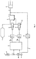
- the brake system shown in FIG. 1 has a Brake cylinder (5), in which a brake pressure is set should be as fast as possible and exactly one Setpoint signal (w) follows.
- the brake cylinder (5) operated with appropriate compressed air then a wheel brake, not shown in FIG. 1 mechanically.
- the brake cylinder (5) is via a compressed air line to the output terminal of a relay valve device (4) connected.
- the relay valve device (4) points next to the output terminal still a supply terminal, which is connected to a compressed air reservoir (1) is, and a control terminal, with two Electromagnetically actuated 2/2-way valves (2, 3) connected is.
- the 2/2-way valves (2, 3) can ever after exposure to electrical actuation signals the control input of the relay valve device (4) optionally with the compressed air storage tank (1) or with one usually associated with the surrounding atmosphere Connect compressed air outlet or such Interrupt connection.
- the valve (2) as an inlet valve and the valve (3) as an outlet valve. This can thus three meaningful states of actuation be adjusted, namely increase, hold and lower the pressure at the control input of the relay valve device (4).
- valve (2) is a normally closed Valve
- valve (3) is around a normally open valve. Because of the de-energized open version of the valve (3) is this valve Normally always applied to an actuating current and thereby closed. A shutdown of the operating current leads to an opening of the valve.
- valve actuation an actuating current called valve actuation
- valve actuation the valve (3) turning off the Actuating current referred to as valve actuation. Different expressed, it is always the switching of the State “valve closed” in the state "valve open” referred to as actuation of the respective valve.
- the relay valve device (4) is used for passing of the pressure applied to the control input to their Compressed air outlet, whereby by the use of such Relay valve means the compressed air flow rate Compared to the 2/2-way valves (2, 3) considerably is larger, so that relatively short filling and Emptying times of the brake cylinder (5) allows become.
- the 2/2-way valves (2, 3) are usually with a connected electronic control unit of which in the greatly simplified representation of FIG. 1, a digital Sensing controller (6), an anti-lock braking system ABS (10) and one each a 2/2-way valve (2, 3) assigned Output amplifier (7, 8) is shown. at the output amplifiers (7, 8) may be, for example to act switching transistors.
- the anti-lock system (10), which velocity signals from a Sensor device (11) receives, is usually in the electronic control unit integrates, e.g. when Electronic or program module.
- the digital sampling controller (6) receives the setpoint signal (w) and an actual value signal (x) and calculates therefrom output signals (y EV , y AV ) to the output amplifiers (7, 8) Actuation of the 2/2-way valves (2, 3) are supplied.
- the setpoint signal (w) is supplied by a brake value transmitter (9) and with one of the anti-lock braking system (10) corrected correction signal corrected so that prevents locking of the wheels during braking becomes.
- the brake value transmitter (9) is mechanically with the Brake pedal of a vehicle connected and enters the Brake pedal operation by the driver representing Signal off.
- the actual value signal (x) is from a Determining brake pressure (p) in the brake cylinder (5) Pressure sensor (12) generated.
- Fig. 1 Other commonly used parts in practice the brake system, such as a pneumatic redundancy path, are not shown in Fig. 1 for simplicity.
- the 2/2-way valves used as intake and exhaust valves (2, 3) have a request dead time, the expresses itself in the fact that for very short operations no compressed air flow flows.
- the relay valve device (4) usually contains a relay piston with a Poetry.
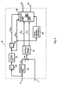
- the relay valve device has a hysteresis in the transmission of the present at the control terminal Pressure value at the pressure outlet. Add to that a dead time behavior of the 2/2-way valves already mentioned. Due to the aforementioned, for a pressure control non-ideal properties of Valves (2, 3, 4) is a suitable, the non-ideal Features compensating construction of the digital sampling controller (6) necessary, as described in more detail below is explained.
- the setpoint signal (w) is first fed to a filter element (20) designed as a setpoint filter, which outputs a modified setpoint signal (w ').
- the setpoint filter (20) serves, in particular when the setpoint signal (w) changes suddenly, the digital sampling controller (6) generates such output signals (y EV , y AV ) which the valve devices (2, 3, 4) can follow.
- a response deadband occurring in the relay valve device (4) is already compensated for at low pressure values in the setpoint filter (20) by skipping a value range of the setpoint signal corresponding to this response deadband. In this case, that range of values which is skipped is advantageously selected such that a design-related response hysteresis of the brake cylinder (5) is not exceeded.
- a control deviation (x W ) is then formed by subtraction, which is fed to an EV / AV controller (21).
- the EV / AV controller (21) is used to determine suitable periods of time with which the 2/2-way valves (2, 3) are to be actuated in a pulse-like manner in order to set a desired brake pressure in the brake cylinder (5).
- Each of the time periods (T EV , T AV ) is determined using a controller with a proportional component and an integral component, wherein the proportionality factor (K PEV , K PAV ) and the integration constant (K IEV , K IAV ) are to be determined by experiments.
- the EV / AV controller (21) is thus designed as a PI controller.
- the operating periods (T EV , T AV ) still each have a constant component (T ANEV , T ANAV ), by means of which the response of the type of 2/2-way valves are compensated.
- the EV / AV controller (21) also generates at a desired pressure increase in the brake cylinder (5), which starts from the zero value of the pressure, an additional time (T O ), which as a further proportion of the actuation period (T EV ) for the intake valve (2) is added additively.
- T O an additional time
- T EV actuation period
- the calculation of the integral components preferably takes place by numerical integration by means of a microprocessor, ie by summation of the individual values of the control deviation (x W ).
- T EV K PEV • x W + K IEV • .SIGMA.X W + T ANEV + T O at a pressure increase from zero value
- T EV K PEV • x W + K IEV • .SIGMA.X W + T ANEV otherwise
- T AV K PAV • x W + K IAV • .SIGMA.X W + T ANAV
- T EV , T AV The thus determined operating periods (T EV , T AV ) are then fed to a three-point controller (26).
- the setpoint signal (w) is additionally supplied to a filter (22) and to a downstream differentiation element (23) and thereby converted into a filtered differentiated setpoint signal (w ⁇ Gef ).
- This signal (w ⁇ Gef ) is supplied to a device (25) for generating a Ventilpulstakts and the three-point controller (26).
- An in a filter (24) by additional filtering of the filtered differentiated setpoint signal (w ⁇ Gef ) obtained signal (w ⁇ 2Gef ) is additionally fed to the three-point controller (26).
- the three - position controller (26) is the device (25) for Generation of a Ventilpulstakt, hereinafter also as Ventilpulstaktmaschineung referred upstream.
- the Ventilpulstaktmaschineung (25) causes the driving frequency, ie the reciprocal of the time interval successive drive pulses, one for the used 2/2-way valves (2, 3) optimal maximum value, preferably smaller than the natural frequency the valves is limited.
- preferred Embodiment of the invention will be the time since Start of the last issued drive pulse measured and only after a minimum waiting time has elapsed Enable signal for the output of the next drive pulse delivered to the three-point controller (26).
- preferred Drive frequencies are in the range of 10 to 20 hertz.
- the minimum waiting time is preferably determined as a function of the reciprocal of the amount of the filtered differentiated setpoint signal (w ⁇ Gef ). This can be done by avoiding a high computational effort, for example, by dividing the value range of the filtered differentiated desired value signal (w ⁇ Gef ) into three ranges and assigning each of these ranges with a predefined minimum waiting time optimized for the respective range.
- the predefined values of the minimum waiting time are determined taking into account the aforementioned determination rule.
- the three-position controller (26) generates in response to its input signals actuation signals (y EV , y AV ) for the 2/2-way valves (2, 3).
- actuation signals y EV , y AV
- the dead zones which are present in the system for a three-position controller ie those positive and negative value ranges of the input signal within which no valve control takes place, can be changed as a function of the desired pressure gradient over time.
- An actuation of the inlet valve (2) is usually carried out in the pressure build-up phase, in other words, when the control variable derived from the control deviation (x W ) used as the input variable for the three-step controller exceeds a threshold value, ie leaves a regulator dead zone in the direction of positive values.
- the threshold thus represents the limit of a regulator deadband.
- the outlet valve is primarily actuated in the pressure reduction phase, as is generally the case with a three-position controller, if the controlled variable derived from the control deviation (x W ) falls below a different threshold value in the direction of negative values.
- the outlet valve (3) can also be operated in the presence of certain conditions in the pressure maintenance phase or even in the pressure build-up phase. Additional prerequisites for this are, in turn, a correspondingly adapted threshold value as well as information about sudden changes in the setpoint signal (w) which have occurred in the past.
- Actuation of the outlet valve (3) in the pressure build-up phase or the intake valve (2) in the pressure reduction phase one also designates as counter-rules.
- the countermeasures serves to reduce overshooting tendencies with rapidly changing pressure. Because the counter-rules a pressure change opposite to that through the setpoint signal (w) causes the predetermined change, So a usually minor pressure reduction in the pressurization phase and a generally minor one Pressure increase in the pressure reduction phase, will be in the following still different between the actual Pressure build-up and countermeasures in the pressure build-up phase or the actual pressure reduction and countermeasures in the pressure reduction phase.
- the factors (k 1, k 2, k 3) is adapted to the respective operating state of the controller displacement of the effective thresholds or changing the dead zone in response to the determined by differentiating and filtering signals (w ⁇ Found, w ⁇ 2Gef ) of the setpoint signal (w) possible.
- suitable dimensioning of the factor (k 1 ) an undesired counter-regulation as a function of the magnitude of an abrupt change of the setpoint signal (w) can be prevented.
- the average control error resulting, for example, from transients can be reduced because the affected by this factor (k 2 ) dead zone of the controller is shifted so that an actuation of the respective valve even at smaller Control deviations is possible and thus a control is initiated in accordance with the PI characteristic described above.
- the setpoint signal (w) which correspond for example to a brake pressure change of 0.25 bar
- a faster and additionally longer response of the controller can be achieved.
- the control can respond very quickly and sensitively to small changes in the setpoint signal (w).
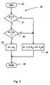
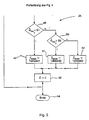
- the following is the operation of the setpoint filter (20) and the valve pulse clock generation (25) according to Art of process steps based on flow charts closer explained.
- the setpoint filter (20) and the valve pulse clock generation (25) could thus be considered parts of a Control program for a microprocessor practically realized become. It would also be possible by appropriate electronic circuitry practical to realize.
- the setpoint filter (20) in the procedural representation as shown in FIG. 3 starts with a block (30).
- a subsequent branch block (31) is first checks whether the time derivative (w ⁇ ) of the Setpoint signal (w) has positive values, d. H. it it is checked whether the setpoint signal (w) increases in time. If this is not the case, then it becomes one in the following explained in more detail allocation block (34) branches. Otherwise, it will be from the branch block (31) branches to the branching block (32).
- the branch block (32) it is checked whether the setpoint signal (w) has values which would lead to pressure values in the relay valve device (4) which lie within the response dead zone of this relay valve device. This is to be expected for values of the setpoint signal (w) below a response value (w H ) to be determined by tests. Therefore, in the presence of values of the setpoint signal (w) below the threshold value (w H ) to the assignment block (33) is branched, in which the modified setpoint signal (w ') is set to the threshold value (w H ).
- a branch is made to the allocation block (34).
- the process section then ends with a block (35).
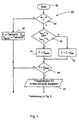
- FIG. 4 is the Ventilpulstaktmaschineung (25) as a further part of the procedure in the form of a two sections divided flow chart shown.
- the process section begins in FIG. 4 with a Block (40).
- the variables used in this section of the procedure serve as counters (Z) and as the maximum permissible end value (Z END ) for the counter (Z).
- the end value (Z END ) thus represents the minimum waiting time, after which a subsequent drive pulse can be output to the valve devices (2, 3) at the earliest on a drive pulse.
- the end value (Z END ) can be set to different values (cycle time 1, cycle time 2, cycle time 3 ) depending on the filtered differentiated setpoint signal (w ⁇ Gef ).
- a brake operation is present (w ' ⁇ 0), then branched to a branch block (43) as shown in FIG.
- the branch block (43) it is checked whether in a past period, a sudden decrease or increase of the setpoint signal has occurred.
- the already mentioned time counters (t SAV , t SEV ) are used, which are then checked to see whether their value is smaller than the threshold value (t S ) also mentioned above. If this is the case, ie if shortly before a sudden change in the setpoint signal (w) has occurred, then the allocation block (44) is branched, in which the counter (Z) is set to the end value (Z END ). Otherwise, in one allocation block (45) of the counter (Z) by an increment value (INC Z) is increased.
- the increment value (Z INC ) may be, for example, a unit of time of one millisecond.
- a branch block (46) is continued, in which it is checked whether the counter (Z) has reached the end value (Z END ). If this is not the case, a branch is made to the already mentioned block (54), with which the method section ends. Otherwise, the end of a minimum waiting time for the output of a new drive pulse has expired, so that in a following data transfer block (47) an enable signal for the output of a drive pulse to the three-level controller (26) is output.
- a new final value (Z END ) is defined in the blocks (48, 49, 50, 51, 52) as a function of the filtered differentiated desired value signal (w ⁇ Gef ).
- it is first checked in a branch block (48) whether the filtered differentiated desired value signal (w ⁇ Gef ) is smaller than a first threshold value (S1). If so, the final value (Z END ) in an allocation block (49) is set to a first minimum wait time (clock time 1). Otherwise, the filtered differentiated setpoint signal (w ⁇ Gef ) is compared with a second threshold (S2) greater than the first threshold (S1).
- the end value (Z END ) in an assignment block (51) is set to a second minimum waiting time (Taktzeit2). Otherwise, in an allocation block (52) the final value (Z END ) is set to a third minimum waiting time (Taktzeit3).
- the minimum waiting times (Taktzeit1, Taktzeit2, Taktzeit3) are chosen so that a reverse proportionality to the values of the filtered differentiated setpoint signal (w ⁇ Gef ) and the threshold values (S1, S2) is present.
Landscapes
- Engineering & Computer Science (AREA)
- Transportation (AREA)
- Mechanical Engineering (AREA)
- Physics & Mathematics (AREA)
- Fluid Mechanics (AREA)
- Electromagnetism (AREA)
- Valves And Accessory Devices For Braking Systems (AREA)
- Regulating Braking Force (AREA)
- Control Of Fluid Pressure (AREA)
- Braking Systems And Boosters (AREA)
Claims (6)
- Dispositif de commande de pression hydraulique, en particulier un dispositif de freinage commandé électriquement pour un véhicule, muni d'un dispositif de soupape (2, 3) en vue de l'augmentation, de la chute ou du maintien d'une pression (p) dans un dissipateur (5), qui présente un distributeur à 2/2 orifices agissant en tant qu'électrovalve d'entrée et un distributeur à 2/2 orifices ouvert non conducteur agissant en tant qu'électrovalve de sortie, dans lequel entre le dispositif de soupape (2, 3) et le dissipateur (5) est disposé un dispositif de soupape à relais (4), caractérisé en ce que le dispositif de soupape (2, 3) peut être alimenté par des signaux de commande en vue de minimiser un déréglage (xw), qui peut apparaítre entre un signal de valeur réelle (x) dérivé de la pression (p) et un signal de valeur prescrite (w), dans lequel, en vue de la génération de signaux de commande pour le dispositif de soupape (2, 3) est prévu un régulateur d'échantillonnage numérique (6), qui contient un montage série constitué d'un élément de filtre (20), d'un régulateur-PI (21) et d'un régulateur à trois points (26).
- Dispositif de commande par pression selon la revendication précédente, caractérisé en ce que le dispositif de soupape (2, 3) peut être alimenté par un signal numérique modulé dans le temps, dont la fréquence de commutation se situe sous la fréquence de résonance du dispositif de soupape (2, 3).
- Dispositif de commande par pression selon l'une des revendications précédentes, caractérisé en ce que le signal de valeur prescrite (w) est dérivé du signal de sortie d'un transmetteur de valeur de freinage (9), lequel délivre un signal électrique représentant la commande d'une pédale de frein.
- Dispositif de commande par pression selon l'une des revendications précédentes, caractérisé en ce que le régulateur d'échantillonnage numérique (6) comporte un dispositif (25) placé en amont d'un régulateur à trois points (26) en vue de la génération d'une cadence d'impulsion de soupape.
- Dispositif de commande par pression selon l'une des revendications précédentes, caractérisé en ce que le régulateur d'échantillonnage numérique 6 comporte un montage série à partir d'un passe-bas (22), d'un élément de différentiation (23) et d'un autre passe-bas (24).
- Dispositif de commande par pression selon l'une des revendications précédentes, caractérisé en ce que le régulateur à trois points (26) présente des zones mortes variables, qui sont modifiables selon les changements brusques apparaissant dans le passé du signal de valeur prescrite (w).
Applications Claiming Priority (2)
| Application Number | Priority Date | Filing Date | Title |
|---|---|---|---|
| DE19905684A DE19905684A1 (de) | 1999-02-11 | 1999-02-11 | Druckregeleinrichtung |
| DE19905684 | 1999-02-11 |
Publications (3)
| Publication Number | Publication Date |
|---|---|
| EP1028043A2 EP1028043A2 (fr) | 2000-08-16 |
| EP1028043A3 EP1028043A3 (fr) | 2003-04-02 |
| EP1028043B1 true EP1028043B1 (fr) | 2005-03-09 |
Family
ID=7897162
Family Applications (1)
| Application Number | Title | Priority Date | Filing Date |
|---|---|---|---|
| EP99124169A Expired - Lifetime EP1028043B1 (fr) | 1999-02-11 | 1999-12-03 | Dispositif de commande de pression hydraulique |
Country Status (2)
| Country | Link |
|---|---|
| EP (1) | EP1028043B1 (fr) |
| DE (2) | DE19905684A1 (fr) |
Cited By (1)
| Publication number | Priority date | Publication date | Assignee | Title |
|---|---|---|---|---|
| DE102015001628A1 (de) | 2015-02-07 | 2016-08-11 | Wabco Gmbh | Verfahren zum Einstellen von Bremsdrücken eines Kraftfahrzeugs über Ansteuerung eines Drucksteuerventils, Bremsanlage zur Durchführung des Verfahrens sowie Kraftfahrzeug |
Families Citing this family (3)
| Publication number | Priority date | Publication date | Assignee | Title |
|---|---|---|---|---|
| DE102009059811B3 (de) * | 2009-12-21 | 2011-09-01 | Knorr-Bremse Systeme für Nutzfahrzeuge GmbH | Mehrkanaliges Druckregelmodul mit nur einem Drucksensor |
| JP5838875B2 (ja) * | 2012-03-16 | 2016-01-06 | トヨタ自動車株式会社 | 液圧制御装置および液圧ブレーキシステム |
| CN103287418B (zh) * | 2013-07-01 | 2017-09-22 | 王石麟 | 汽车自动应急辅助制动装置 |
Family Cites Families (17)
| Publication number | Priority date | Publication date | Assignee | Title |
|---|---|---|---|---|
| DE2811345C2 (de) * | 1978-03-16 | 1986-12-11 | Knorr-Bremse AG, 8000 München | Druckregler für pneumatische Drücke, insbesondere in Fahrzeugen |
| DE3138647A1 (de) * | 1981-09-29 | 1983-04-14 | Dr.Ing.H.C. F. Porsche Ag, 7000 Stuttgart | "steuervorrichtung fuer magnetventile" |
| DE3240277A1 (de) * | 1982-10-30 | 1984-05-03 | Robert Bosch Gmbh, 7000 Stuttgart | Druckmittel-bremsanlage |
| DE3543145C2 (de) * | 1985-12-06 | 1995-08-03 | Bosch Gmbh Robert | Elektrisches Bremssystem für ein Fahrzeug |
| DE3636140C2 (de) * | 1986-10-24 | 1997-03-20 | Knorr Bremse Ag | Druckregler |
| GB8817796D0 (en) * | 1988-07-26 | 1988-09-01 | Bendix Ltd | Fluid pressure control relay valve device & apparatus |
| DE3927110A1 (de) * | 1989-08-17 | 1991-02-21 | Bosch Gmbh Robert | Magnetventil mit erregerstrom-steuervorrichtung |
| DE4004502A1 (de) * | 1990-02-14 | 1991-08-22 | Daimler Benz Ag | Elektronisch geregelte druckmittel-bremseinrichtung |
| DE4029793C2 (de) * | 1990-09-20 | 1999-05-06 | Bosch Gmbh Robert | Hydraulische Fahrzeugbremsanlage |
| DE4031551C1 (en) * | 1990-10-05 | 1992-01-30 | Mercedes-Benz Aktiengesellschaft, 7000 Stuttgart, De | Braking installation with electronically-regulated pressure medium - keeps 3-2 way valve in working position during slip-regulated braking process by electromagnet valve |
| GB9102472D0 (en) * | 1991-02-05 | 1991-03-20 | Lucas Ind Plc | Braking system for a vehicle |
| DE4141995A1 (de) | 1991-12-19 | 1993-06-24 | Bosch Gmbh Robert | Druckluft-bremsanlage, insbesondere fuer nutzfahrzeuge |
| JPH0736551A (ja) * | 1993-07-20 | 1995-02-07 | Smc Corp | 電空レギュレータ用圧力制御装置 |
| DE4406235A1 (de) * | 1994-02-25 | 1995-08-31 | Wabco Vermoegensverwaltung | Druckregeleinrichtung |
| DE4428929A1 (de) * | 1994-08-16 | 1996-02-22 | Wabco Gmbh | Verfahren und Einrichtung zur Druckregelung |
| DE19548207A1 (de) * | 1995-12-22 | 1997-06-26 | Bosch Gmbh Robert | Hydraulische Fremdkraftfahrzeugbremsanlage mit wenigstens einem elektrisch steuerbaren Ventil |
| DE19654427B4 (de) * | 1996-12-24 | 2009-08-13 | Robert Bosch Gmbh | Verfahren und Vorrichtung zur Regelung des Drucks in wenigstens einer Radbremse |
-
1999
- 1999-02-11 DE DE19905684A patent/DE19905684A1/de not_active Withdrawn
- 1999-12-03 DE DE59911727T patent/DE59911727D1/de not_active Expired - Lifetime
- 1999-12-03 EP EP99124169A patent/EP1028043B1/fr not_active Expired - Lifetime
Cited By (3)
| Publication number | Priority date | Publication date | Assignee | Title |
|---|---|---|---|---|
| DE102015001628A1 (de) | 2015-02-07 | 2016-08-11 | Wabco Gmbh | Verfahren zum Einstellen von Bremsdrücken eines Kraftfahrzeugs über Ansteuerung eines Drucksteuerventils, Bremsanlage zur Durchführung des Verfahrens sowie Kraftfahrzeug |
| US11198421B2 (en) | 2015-02-07 | 2021-12-14 | Zf Cv Systems Europe Bv | Method for adjusting brake pressures of a vehicle via control of a pressure control valve, brake system for carrying out the method and motor vehicle |
| DE102015001628B4 (de) | 2015-02-07 | 2026-05-07 | Zf Cv Systems Europe Bv | Verfahren zum Einstellen von Bremsdrücken eines Kraftfahrzeugs über Ansteuerung eines Drucksteuerventils, Bremsanlage zur Durchführung des Verfahrens sowie Kraftfahrzeug |
Also Published As
| Publication number | Publication date |
|---|---|
| EP1028043A2 (fr) | 2000-08-16 |
| DE19905684A1 (de) | 2000-08-17 |
| DE59911727D1 (de) | 2005-04-14 |
| EP1028043A3 (fr) | 2003-04-02 |
Similar Documents
| Publication | Publication Date | Title |
|---|---|---|
| EP0669565B1 (fr) | Dispositif de régulation de pression | |
| DE2811345C2 (de) | Druckregler für pneumatische Drücke, insbesondere in Fahrzeugen | |
| EP2152555B1 (fr) | Procédé de correction des caractéristiques de commande de soupapes hydraulique à fonctionnement analogique dans des systèmes de freinage d'automobiles | |
| EP0697317B1 (fr) | Procédé et dispositif pour le contrÔle de pression | |
| EP1625058B1 (fr) | Procede d'apprentissage de courbes caracteristiques de commande pour vannes hydrauliques | |
| EP2387523B1 (fr) | Procédé pour exploiter un système hydraulique ou pneumatique | |
| EP3339992A1 (fr) | Procédé de réglage et/ou de commande d'un appareil de champ électropneumatique | |
| EP0840684B1 (fr) | Procede et dispositif de commande d'une vanne electromagnetique | |
| EP3481686A1 (fr) | Dispositif et procédé de commande de soupape | |
| EP0381957A1 (fr) | Système de freinage anti-blocage avec limitation du moment de lacet | |
| DE19848960B4 (de) | Verfahren und Vorrichtung zur Steuerung eines Drucksteuerventils, insbesondere einer Bremsanlage | |
| EP0473914B1 (fr) | Système de régulation d'un actuateur dans un moteur à combustion | |
| EP1808348B1 (fr) | Réglage de pression précise et sans usure à l'aide de soupapes de commande destinées au réglage de la pression des freins dans des véhicules sur rails | |
| EP3724046B1 (fr) | Système de freinage comportant un dispositif de correction du temps d'ouverture d'une soupape et procédé de correction du temps d'ouverture de la soupape | |
| EP1028043B1 (fr) | Dispositif de commande de pression hydraulique | |
| DE4214547A1 (de) | Fahrzeugbremssystem | |
| DE19727945B4 (de) | Verfahren und Vorrichtung zur geregelten Ansteuerung eines proportional betriebenen Magnetventils | |
| DE2908871A1 (de) | Fahrzeug-bremsanlage | |
| DE10200771B4 (de) | Verfahren zur Regelung des Bremsdruckes mit Proportionalventilen | |
| DE102009051514A1 (de) | Vorrichtung und Verfahren zur Druckregelung eines Volumens | |
| DE69515629T2 (de) | Methode und Ventilanordnung zur Regelung eines Pilotsignals | |
| WO2002061517A1 (fr) | Dispositif et procede de regulation du comportement dynamique d'une roue | |
| EP1117578B1 (fr) | Dispositif pour la commande de la force de freinage d'un systeme de freinage | |
| EP1409306B1 (fr) | Procede et dispositif pour detecter une pression residuelle dans un systeme de freinage, en particulier dans un cylindre de frein | |
| DE102009015992A1 (de) | Verfahren zur Beschleunigungsregelung in einem Kraftfahrzeug |
Legal Events
| Date | Code | Title | Description |
|---|---|---|---|
| PUAI | Public reference made under article 153(3) epc to a published international application that has entered the european phase |
Free format text: ORIGINAL CODE: 0009012 |
|
| AK | Designated contracting states |
Kind code of ref document: A2 Designated state(s): AT BE CH CY DE DK ES FI FR GB GR IE IT LI LU MC NL PT SE |
|
| AX | Request for extension of the european patent |
Free format text: AL;LT;LV;MK;RO;SI |
|
| PUAL | Search report despatched |
Free format text: ORIGINAL CODE: 0009013 |
|
| AK | Designated contracting states |
Kind code of ref document: A3 Designated state(s): AT BE CH CY DE DK ES FI FR GB GR IE IT LI LU MC NL PT SE |
|
| AX | Request for extension of the european patent |
Extension state: AL LT LV MK RO SI |
|
| 17P | Request for examination filed |
Effective date: 20031002 |
|
| 17Q | First examination report despatched |
Effective date: 20031124 |
|
| AKX | Designation fees paid |
Designated state(s): DE FR SE |
|
| GRAP | Despatch of communication of intention to grant a patent |
Free format text: ORIGINAL CODE: EPIDOSNIGR1 |
|
| GRAS | Grant fee paid |
Free format text: ORIGINAL CODE: EPIDOSNIGR3 |
|
| GRAA | (expected) grant |
Free format text: ORIGINAL CODE: 0009210 |
|
| AK | Designated contracting states |
Kind code of ref document: B1 Designated state(s): DE FR SE |
|
| REG | Reference to a national code |
Ref country code: SE Ref legal event code: TRGR |
|
| REG | Reference to a national code |
Ref country code: IE Ref legal event code: FG4D Free format text: GERMAN |
|
| REF | Corresponds to: |
Ref document number: 59911727 Country of ref document: DE Date of ref document: 20050414 Kind code of ref document: P |
|
| PLBE | No opposition filed within time limit |
Free format text: ORIGINAL CODE: 0009261 |
|
| STAA | Information on the status of an ep patent application or granted ep patent |
Free format text: STATUS: NO OPPOSITION FILED WITHIN TIME LIMIT |
|
| ET | Fr: translation filed | ||
| 26N | No opposition filed |
Effective date: 20051212 |
|
| REG | Reference to a national code |
Ref country code: FR Ref legal event code: PLFP Year of fee payment: 17 |
|
| REG | Reference to a national code |
Ref country code: FR Ref legal event code: PLFP Year of fee payment: 18 |
|
| REG | Reference to a national code |
Ref country code: FR Ref legal event code: PLFP Year of fee payment: 19 |
|
| PGFP | Annual fee paid to national office [announced via postgrant information from national office to epo] |
Ref country code: SE Payment date: 20181219 Year of fee payment: 20 |
|
| PGFP | Annual fee paid to national office [announced via postgrant information from national office to epo] |
Ref country code: FR Payment date: 20181218 Year of fee payment: 20 |
|
| PGFP | Annual fee paid to national office [announced via postgrant information from national office to epo] |
Ref country code: DE Payment date: 20181231 Year of fee payment: 20 |
|
| REG | Reference to a national code |
Ref country code: DE Ref legal event code: R071 Ref document number: 59911727 Country of ref document: DE |
|
| REG | Reference to a national code |
Ref country code: SE Ref legal event code: EUG |