EP1028223A2 - Entraínement auxiliaire pour l'entraínement auxiliaire de fermetures de bâtiment - Google Patents
Entraínement auxiliaire pour l'entraínement auxiliaire de fermetures de bâtiment Download PDFInfo
- Publication number
- EP1028223A2 EP1028223A2 EP00102441A EP00102441A EP1028223A2 EP 1028223 A2 EP1028223 A2 EP 1028223A2 EP 00102441 A EP00102441 A EP 00102441A EP 00102441 A EP00102441 A EP 00102441A EP 1028223 A2 EP1028223 A2 EP 1028223A2
- Authority
- EP
- European Patent Office
- Prior art keywords
- auxiliary drive
- rotary member
- drive device
- rotation
- engagement
- Prior art date
- Legal status (The legal status is an assumption and is not a legal conclusion. Google has not performed a legal analysis and makes no representation as to the accuracy of the status listed.)
- Granted
Links
Images


Classifications
-
- E—FIXED CONSTRUCTIONS
- E06—DOORS, WINDOWS, SHUTTERS, OR ROLLER BLINDS IN GENERAL; LADDERS
- E06B—FIXED OR MOVABLE CLOSURES FOR OPENINGS IN BUILDINGS, VEHICLES, FENCES OR LIKE ENCLOSURES IN GENERAL, e.g. DOORS, WINDOWS, BLINDS, GATES
- E06B9/00—Screening or protective devices for wall or similar openings, with or without operating or securing mechanisms; Closures of similar construction
- E06B9/56—Operating, guiding or securing devices or arrangements for roll-type closures; Spring drums; Tape drums; Counterweighting arrangements therefor
- E06B9/68—Operating devices or mechanisms, e.g. with electric drive
- E06B9/74—Operating devices or mechanisms, e.g. with electric drive adapted for selective electrical or manual operation
Definitions
- the invention relates to an auxiliary drive device for auxiliary driving one with Main drive unit drivable building lock - especially gates like Ceiling sectional door or roller door - with a preferably manually operated one
- Auxiliary drive rotating element which can be set in rotating rotation - such as auxiliary drive wheel, Auxiliary drive shaft or the like - that for the auxiliary drive with a rotatable Tap rotary element that is assigned to the drive train of the building lock and for common rotation connected to it or integrated therein, for tapping the auxiliary drive rotation can be brought into engagement.
- Auxiliary drive devices are known for gate drives in the form of emergency hand chain drives. They serve the purpose of being operable with an electric motor or the like
- the gate can be opened or closed even in the event of a power failure.
- the reel sprocket is by means of a tap rotating member in the form of a coupling device with the main drive train and for example with a door drive shaft connectable.
- An example of such an auxiliary drive device of the The type mentioned at the outset is known from DE 34 26 428 C2, to those for further construction Details are expressly referred to.
- auxiliary drive device is a with the auxiliary drive rotary member in the form of a stationary spool sprocket Coupling device with an approach on which a driver is pivotally mounted, the Swivel into approaches on a motor shaft (rotary tapping element) to actuate the clutch can.
- the pivoting takes place via a curve-pin arrangement when the reel sprocket is turned.
- a disadvantage of this and also of other emergency hand chain drives that were previously on the market is its high transmission technology caused by the coupling device Expenditure.
- they usually have an unfavorable gear ratio for example the reel sprocket is coupled directly to the motor shaft as in DE 34 26 428 C2 is due to the mostly used high-speed electric motors geared translated is connected to the door drive shaft. Because of that is with Many of the emergency hand chain drives currently on the market are very slow The gate can be raised and lowered.
- the object of the invention is to provide an auxiliary drive device of the type mentioned create that is technically simpler, takes up little space and still offers a translation that is favorable for the respective emergency operation.
- auxiliary drive rotary member in one relative to the tap rotary member - with at least one movement component - parallel to whose rotational plane movably supported bearing member is mounted such that the in a rest position decoupled rotary elements from the rest position with at least one movement component movable relative to each other in their respective plane of rotation and thereby above themselves in its entirety extending essentially in the circumferential direction on the rotating members Engagement or toothed areas for forming a transmission gear in preferably positive engagement can be brought together.
- the auxiliary drive rotary member - that is to say, a reel sprocket or an integral or connected part - and the tap rotary link formed as a drive member and output member of a transmission gear.
- the two rotary members are movable relative to each other in their respective radial directions and decoupled from one another in a rest position. At least in the plane of rotation one of the rotating members - preferably in the rotating plane common to the two rotating members with a corresponding rotary link arrangement - relative movement to one another to be circumferentially extending areas of the two rotating members are engaged and thus the two rotary links coupled together.
- the relative movement between the two rotating members is realized in a simple manner, when the bearing member used to support the auxiliary drive rotary member is relative to the tap rotary member around a pivot axis running at a distance from its axis of rotation is pivotally mounted that the engagement or Gearing areas by pivoting the bearing member from its rest position can be brought out into engagement.
- a particularly preferred embodiment of the invention is achieved when the pivot axis is approximately parallel to the axis of rotation of the auxiliary drive rotating member runs at a distance from it and a braking device is provided, the force opposing the rotation of the auxiliary drive rotary member on the auxiliary drive rotary member exercises.
- the auxiliary drive rotary member resists due to Braking device first of the rotation.
- the interaction of the braking device with the auxiliary drive rotating member is chosen so that the pull on the traction device first the pivoting movement of the bearing member is initiated until the two Rotary members come into engagement with each other. Since the complete intervention of the Rotary members can not pivot the bearing member further - which preferably by a stop device for limiting the pivoting movement is supported - is a train exerted on the traction device via the engagement of the traction device with the Auxiliary drive rotary element converted into auxiliary drive rotary motion.
- the bearing member according to the preferred embodiment is in its rest position biased. In principle, this would also be due to weight arrangements or the like possible, but preferably at least one spring device is provided for pretensioning.
- the already mentioned stop device for limiting the relative movement in particular the pivoting movement, is provided Jamming of the two rotating elements due to excessive ones causing the relative movement Forces prevented.
- the two rotary links could be designed in many ways, it would be Example of a version with two differently toothed pinions.
- auxiliary drive rotary member has an annular area has, on the radially inwardly directed wall of the engagement or toothing area of the auxiliary drive rotary member is formed, wherein the annular region the one provided on its outer circumference with its engagement or toothing area Tap rotary member surrounds and wherein the inner diameter of the annular region is larger is as the outer diameter of the engaging or toothed portion of the tap rotary member.
- the auxiliary drive rotary member has, for example, an internal toothing annular area on which the tapping rotary member or at least its engagement or Surrounding tooth area.
- the auxiliary drive rotary member could, for example be designed completely as a ring, but a pot shape or the like would also be possible.
- the auxiliary drive rotary member is preferably at least partially ring-shaped Traction means disc, in particular chain disc, or more preferably at least in some areas annular traction wheel, in particular sprocket, on which or which the traction means, for example a chain, preferably for transmitting rotational movement in positive engagement, is performed.
- auxiliary drive rotary member surrounding the tap rotary member that the bearing member supporting the auxiliary drive rotary member can be pivoted from its rest position either clockwise or counterclockwise to either side in order to engage or detect the rotary members on the one hand or on the other hand a plane that is intended to run through the pivot axis and the axis of rotation of the auxiliary drive rotary member.
- the rest position can be chosen such that the The axis of rotation of the rotary tapping element lies in this plane or to the left or right of it, as long as the two rotary elements are decoupled in the rest position.A smooth changeover is, of course, most likely to be achieved when the axis of rotation of the tapping rotary element is in the rest position everything coincides with this imaginary level.
- the axes of rotation of the rotary members are essentially coincident in the rest position, ie the two rotary members lie coaxially, in particular coaxially one inside the other, in the rest position.
- the tapping rotary member is a toothed pinion
- the engagement area of the auxiliary drive rotary member is also provided with a toothing.
- the latter is in In the case of the at least partially annular auxiliary drive rotary member, preferably one Internal teeth. Since the two rotating elements in the relative movement as a pivoting movement executing configuration intermesh in an arcuate relative movement path, the shape of the teeth is special for perfect engagement essential. In the case of an interlocking rotary link arrangement in the common plane of rotation pivoting auxiliary drive rotary member were the best intervention results achieved with toothing, as shown in the accompanying figures. Accordingly preferred that the teeth in cross-section triangular teeth, preferably with Are spaced from each other.
- the bearing member is preferably a pivotable on a stationary, the main drive unit assigned aggregate housing, in particular gear housing, mounted Two-part housing for use, the radially outer areas of the auxiliary drive rotating member includes in stock.
- the braking device preferably comprises a corrugated disk or corrugated disk, spring washer or the like friction element for exerting a defined frictional force on the Auxiliary drive rotary member.
- the brake disc is between one part of the two-part housing and radial surfaces, in particular circular surfaces, of the auxiliary drive member arranged.
- a further preferred embodiment of the invention characterized by a Relative or pivoting switchable switching device for decommissioning or keeping the main drive unit out of operation when the bearing member is out of its rest position is deflected or pivoted.
- auxiliary drive device in a preferred embodiment as an emergency hand chain drive for a door drive - in particular Shaft gate drive - has the auxiliary drive device according to the invention as an auxiliary drive rotary member a reel sprocket with an internal ring gear on, which in a swiveling Housing is stored.
- This is made up of a chain sprocket and a swiveling housing Unit is about a pivot point against one on the motor shaft of the main drive unit arranged pinion pivotable to the right or left side. The pivoting of the housing with reel sprocket is done by pulling on one the chain strands are exercised.
- the position of the pivot point, the leverage in the event of an intervention, the tooth shape of the ring gear and the pinion, the restoring force of the compression springs and stops to limit the pivoting movement are important.
- the predetermined by this Individual parameters are easy for the person skilled in the art by trials for each individual case optimizable.
- the frictional force acting on the reel sprocket is also too high take into account and adjust if necessary.
- the restoring force of the compression springs and the Frictional force on the reel sprocket are the criteria for perfect shifting.
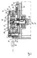
- An auxiliary drive device for auxiliary driving of a shaft gate drive has Reel sprocket 12 with endless endless chain 14 placed over it.
- the endless circular chain 14 is guided over the reel sprocket 12 and positively engages in a reel chain profile 16 on the reel sprocket 12.
- the reel sprocket 12 is the reel sprocket in one 12 surrounding two-part housing 18 mounted.
- the housing 18 is by means of a pivot pin 20 pivotally mounted on a flange cover 22.
- the Flange cover 22 is fixed to a transmission housing by means of screw connections 24 or the like 26 (see Figure 2) of the shaft gate drive attached.
- Two left and right of the Swing pin 20 attached compression springs 28 tension the two-part housing 18 the reel sprocket 12 in a stable position in the middle.
- the reel sprocket 12 is generally ring-shaped. On the inner ring wall 30 this ring element 12 has an internal toothing 32. Between that as a bearing member for the reel sprocket 12 serving housing 18 and the reel sprocket 12 is a Friction element 34 is provided as a braking device. In the example shown, this applies Friction element 34 between radially directed surfaces of the reel sprocket and the housing 18 on.
- the friction element 34 is through a corrugated disc, i.e. corrugated disc, or Spring washer 36 formed.
- a Pinion 40 arranged in the space 38 surrounded by the reel sprocket 12 and its internal toothing 32 .
- the pinion 40 is for common rotation with a pinion shaft 42 connected, which is connected to the main drive train of the door drive. For this passes through the pinion shaft 42 and is in the interior of the same flanged to a worm wheel 44 of a gear transmission.
- the flange cover 22 is provided with a projection 46 provided, on which two stop surfaces 48 are formed.
- a switch 50 is also provided on the flange cover 22, which switches into the power supply circuit of the motor unit of the door operator is switched and when actuated by pressing a switching element 52, the motor drive unit (not shown) without current switches or keeps currentless.
- the pivot pin 20 At the opposite end of the pivot pin 20 that is acts as a bearing member housing 18 with a button 54 for switching the Switch 50 provided.
- the button 54 has a recess 56 in the center, which is in this way connected to the switching element 52 of the Switch 50 corresponds to that shown in Figures 1 and 2, by the compression springs 28 maintained stable central rest position of the housing 18 and the reel sprocket 12 the switching element 52 remains unactuated.
- the internal toothing 32 of the reel sprocket 12 has a regular circumference distributed spaced teeth 60 triangular in cross section.
- the teeth 60 extend extending in the axial direction over the entire toothed area forming the internal toothing 32 62.
- the external toothing 64 of the toothed pinion 40 corresponds to this formed extends in the axial direction over the entire external tooth area and has axially extending rib-like teeth 66 with a triangular cross section and spaces 68 therebetween.
- the axis of rotation of the toothed pinion 40 lies in a plane E (cutting plane of FIG. 2) that is intended to run through the pivot axis S formed by the pivot pin 20 and the axis of rotation of the reel sprocket 12.
- the axes of rotation D 1 and D 2 of the reel sprocket 12 and the pinion 40 coincide in this rest position - the two rotating members 12, 40 are thus arranged coaxially to one another.
- the tooth flanks of the teeth 60 and 66 are inclined in such a way that they are designed to correspond to one another in the tangential contact region 70 during this engagement.
- the respectively opposite tooth flanks are designed accordingly for the engagement on the other side when the reel sprocket wheel rotates in the opposite direction.
- the reel sprocket resists due to the braking effect of the friction element 34, which has a defined frictional force on the reel sprocket 12 exercises, initially the rotary movement.
- the traction on the endless rotary chain then causes a pivoting moment, which pivots as the bearing member of the Reel sprocket 12 serving housing 18 causes.
- the toothing area 32 and the the peripheral area 64 of the toothed pinion 40 and thus the Teeth 66, 60 are brought into engagement by the pivoting movement.
- the switching element 52 of the switch 50 comes out of the Notch or recess 56 and is actuated by the button 54, causing the power supply to the motor drive unit interrupted when the auxiliary drive device is actuated becomes.
- auxiliary drive device - in particular for a door drive - is therefore described been in the around a pinion 40 with circumferentially extending external teeth 64 is a two-part housing 18 with an embedded reel sprocket 12, which has a Internal teeth 32 and a reel chain profile 16 has and as an auxiliary drive rotating member acts to be pivotable about a pivot axis S. That from housing 18 and reel sprocket 12 formed system - pivoting unit 21 - is pivotable on one Flange cover 22 constructed, which is screwed in place on the gear housing 26. about two compression springs 28, the pivoting unit 21 is held in a stable position in the center.
- the Pinion 40 is rotationally fixed with its pinion shaft 42 in a worm wheel 44 of a door drive gear.
- the reel chain or endless circular chain 14 is tangentially tangled in two-part housing 18 secured against rotation - form-fitting - around the reel sprocket 12. Between the upper housing part 72 - one part of the two-part housing 18 - and the reel sprocket 12 is a corrugated disk 36 on the circular ring surfaces in contact arranged to generate a defined frictional force. Will be on the reel chain or endless round chain 14 pulled, the housing 18 inclines with the reel sprocket 12 the pinion 40; the teeth 60, 66 interlock.
- a two-sided pivoting option could also only be a one-sided pivoting option be provided.
- the reel sprocket could also be provided with external teeth be and in a pinion arranged outside the same by pivoting movement be designed to be able to engage.
- the invention relates to an auxiliary drive device (10) for auxiliary driving of a a main drive unit drivable building lock - especially gate like Ceiling sectional door or roller door - with a preferably manually operated one Traction means (14) rotatable auxiliary drive rotary member (12) for the auxiliary Drive with a rotatable tap rotary member (40), which is the main drive train of the building lock assigned and connected to it for joint rotation or in it is integrated, can be brought into engagement for tapping the auxiliary drive rotary movement.
- auxiliary drive rotary member (12) be in a relative to the tap rotary member (40) - with at least one movement component - movable parallel to its plane of rotation held bearing member (18) is mounted such that the decoupled in a rest position Rotating members (12, 40) from the rest position with at least one movement component parallel to their plane of rotation, movable relative to one another and thereby over themselves in their entirety extending substantially in the circumferential direction on the rotary members (12, 40) Engagement or toothed areas (62, 64) for forming a transmission gear in preferably interlocking engagement can be brought together.
Landscapes
- Engineering & Computer Science (AREA)
- Structural Engineering (AREA)
- Architecture (AREA)
- Civil Engineering (AREA)
- Power-Operated Mechanisms For Wings (AREA)
Applications Claiming Priority (2)
| Application Number | Priority Date | Filing Date | Title |
|---|---|---|---|
| DE29902442U DE29902442U1 (de) | 1999-02-11 | 1999-02-11 | Hilfsantriebsvorrichtung zum hilfsweisen Antreiben eines Gebäudeverschlusses |
| DE29902442U | 1999-02-11 |
Publications (3)
| Publication Number | Publication Date |
|---|---|
| EP1028223A2 true EP1028223A2 (fr) | 2000-08-16 |
| EP1028223A3 EP1028223A3 (fr) | 2002-10-16 |
| EP1028223B1 EP1028223B1 (fr) | 2004-04-28 |
Family
ID=8069256
Family Applications (1)
| Application Number | Title | Priority Date | Filing Date |
|---|---|---|---|
| EP00102441A Expired - Lifetime EP1028223B1 (fr) | 1999-02-11 | 2000-02-04 | Entraînement auxiliaire pour l'entraînement auxiliaire de fermetures de bâtiment |
Country Status (2)
| Country | Link |
|---|---|
| EP (1) | EP1028223B1 (fr) |
| DE (2) | DE29902442U1 (fr) |
Cited By (4)
| Publication number | Priority date | Publication date | Assignee | Title |
|---|---|---|---|---|
| US9341022B2 (en) | 2014-07-24 | 2016-05-17 | Chamberlain Australia Pty Ltd. | Sensing manual drive operation of a movable barrier |
| DE102016115773B3 (de) * | 2016-07-15 | 2017-05-18 | Hörmann KG Antriebstechnik | Torantriebsvorrichtung mit Zuluftfunktion für ein Tor, insbesondere für ein Rauch- oder Wärmeabzugssystem, damit angetriebenes Tor sowie Nachrüstsatz |
| WO2018086763A1 (fr) | 2016-11-09 | 2018-05-17 | Hörmann KG Antriebstechnik | Dispositif adaptateur de commande d'arrivée d'air pour un dispositif de commande de porte, dispositif de commande de porte et porte ainsi commandée |
| EP4130417A1 (fr) * | 2021-08-06 | 2023-02-08 | Hörmann KG Antriebstechnik | Dispositif d'entraînement auxiliaire permettant d'entraîner de manière auxiliaire un élément de fermeture de bâtiment pouvant être entraîné au moyen d'un module d'entraînement principal et système d'entraînement |
Families Citing this family (2)
| Publication number | Priority date | Publication date | Assignee | Title |
|---|---|---|---|---|
| DE102009007634B4 (de) | 2008-03-12 | 2017-04-27 | Hörmann KG Antriebstechnik | Torantriebsvorrichtung, insbesondere Direktantrieb |
| DE102009050185A1 (de) | 2009-04-22 | 2010-10-28 | Hörmann KG Antriebstechnik | Torantriebsvorrichtung mit Absolutwegsensor |
Citations (1)
| Publication number | Priority date | Publication date | Assignee | Title |
|---|---|---|---|---|
| DE3426428C1 (de) | 1984-07-18 | 1985-08-22 | Rolf 5000 Köln Machill | Vorrichtung zur hilfweisen Betätigung von Antrieben, insbesondere von Torantrieben |
Family Cites Families (5)
| Publication number | Priority date | Publication date | Assignee | Title |
|---|---|---|---|---|
| DE889213C (de) * | 1951-06-08 | 1953-09-07 | Windenfabrik Gottfried Schober | Seilwinde durch Horizontalzug mit Schneckenantrieb der Seiltrommel |
| US2819628A (en) * | 1954-08-16 | 1958-01-14 | Coolsson Company | Door control device |
| DE3402107A1 (de) * | 1984-01-21 | 1985-08-01 | W. u. H. Neukirchen GmbH & Co KG, 4060 Viersen | Antrieb fuer tore, insbesondere schiebe-falttore |
| CA1260025A (fr) * | 1985-11-14 | 1989-09-26 | M & I Door Systems Limited | Mecanisme de manoeuvre (ouverture et fermeture) d'une porte de complexe industriel |
| JPH10299857A (ja) * | 1997-04-21 | 1998-11-13 | Copal Co Ltd | ギヤブロック |
-
1999
- 1999-02-11 DE DE29902442U patent/DE29902442U1/de not_active Expired - Lifetime
-
2000
- 2000-02-04 DE DE50006197T patent/DE50006197D1/de not_active Expired - Lifetime
- 2000-02-04 EP EP00102441A patent/EP1028223B1/fr not_active Expired - Lifetime
Patent Citations (1)
| Publication number | Priority date | Publication date | Assignee | Title |
|---|---|---|---|---|
| DE3426428C1 (de) | 1984-07-18 | 1985-08-22 | Rolf 5000 Köln Machill | Vorrichtung zur hilfweisen Betätigung von Antrieben, insbesondere von Torantrieben |
Cited By (5)
| Publication number | Priority date | Publication date | Assignee | Title |
|---|---|---|---|---|
| US9341022B2 (en) | 2014-07-24 | 2016-05-17 | Chamberlain Australia Pty Ltd. | Sensing manual drive operation of a movable barrier |
| US9765569B2 (en) | 2014-07-24 | 2017-09-19 | Chamberlain Australia Pty Ltd. | Sensing manual drive operation of a movable barrier |
| DE102016115773B3 (de) * | 2016-07-15 | 2017-05-18 | Hörmann KG Antriebstechnik | Torantriebsvorrichtung mit Zuluftfunktion für ein Tor, insbesondere für ein Rauch- oder Wärmeabzugssystem, damit angetriebenes Tor sowie Nachrüstsatz |
| WO2018086763A1 (fr) | 2016-11-09 | 2018-05-17 | Hörmann KG Antriebstechnik | Dispositif adaptateur de commande d'arrivée d'air pour un dispositif de commande de porte, dispositif de commande de porte et porte ainsi commandée |
| EP4130417A1 (fr) * | 2021-08-06 | 2023-02-08 | Hörmann KG Antriebstechnik | Dispositif d'entraînement auxiliaire permettant d'entraîner de manière auxiliaire un élément de fermeture de bâtiment pouvant être entraîné au moyen d'un module d'entraînement principal et système d'entraînement |
Also Published As
| Publication number | Publication date |
|---|---|
| EP1028223B1 (fr) | 2004-04-28 |
| DE50006197D1 (de) | 2004-06-03 |
| EP1028223A3 (fr) | 2002-10-16 |
| DE29902442U1 (de) | 2000-07-06 |
Similar Documents
| Publication | Publication Date | Title |
|---|---|---|
| EP0175996B1 (fr) | Unité d'entraînement notamment pour le déplacement de glaces, de toits ouvrants, de sièges et d'accessoires d'automobiles similaires | |
| DE69107909T2 (de) | Antriebsvorrichtung für ein Fahrzeug fortbewogen durch Muskelkraft, wie z.B. ein Rollstuhl. | |
| DE69620339T2 (de) | Fahrzeugstürstelltrieb | |
| DE4403574C1 (de) | Antriebsvorrichtung für ein zwischen Endstellungen verstellbares Teil eines Fahrzeuges | |
| DE3118634C2 (de) | Verstellantrieb mit Schlingfederbremselement in einem Kraftfahrzeug, insbesondere für einen Fensterheber | |
| DE69202660T2 (de) | Hebezeug. | |
| DE2618543C3 (de) | Vorrichtung zum Ver- und Entriegeln eines Drehkreuzes | |
| DE3522706C2 (de) | Vorrichtung für Linearantrieb | |
| DE3420789C2 (fr) | ||
| DE19734815C1 (de) | Antriebsvorrichtung für ein verstellbares Fahrzeugteil | |
| EP1028223B1 (fr) | Entraînement auxiliaire pour l'entraînement auxiliaire de fermetures de bâtiment | |
| AT402311B (de) | Absperreinrichtung | |
| DE8634796U1 (de) | Drehantriebsvorrichtung für das Aufrollrohr eines Rollvorhanges, Rolladens o.dgl. | |
| DE2914364A1 (de) | Uebertragungsvorrichtung | |
| WO1999018318A1 (fr) | Ensemble d'entrainement d'arbre pour portes comportant un arbre a barre de torsion et/ou un arbre d'entrainement | |
| CH669636A5 (fr) | ||
| DE60200659T2 (de) | Irreversibel oder reversibel regelbare Bewegungsübertragungsvorrichtung für einen motorisierten Tür- und Torantrieb. | |
| EP1227209B1 (fr) | Dispositif d'entraînement pour portes | |
| EP4130417B1 (fr) | Système d'entraînement et utilisation d'un dispositif d'entraînement auxiliaire permettant d'entraîner de manière auxiliaire un élément de fermeture de bâtiment pouvant être entraîné au moyen d'un module d'entraînement principal | |
| DE3021114A1 (de) | Schwenktuere fuer absperrungen in durchgangsanlagen | |
| DE2754754A1 (de) | Getriebe mit einer integrierten einrichtung zur begrenzung der abtriebsleistung | |
| DE10002062B4 (de) | Karusselltür | |
| DE29812863U1 (de) | Steuerung für einen stufenlosen Kraftwagentürfeststeller | |
| DE3824949A1 (de) | Getriebe fuer sektional- oder rolltore | |
| DE19548849B4 (de) | Abschaltvorrichtung für eine angetriebene Welle |
Legal Events
| Date | Code | Title | Description |
|---|---|---|---|
| PUAI | Public reference made under article 153(3) epc to a published international application that has entered the european phase |
Free format text: ORIGINAL CODE: 0009012 |
|
| AK | Designated contracting states |
Kind code of ref document: A2 Designated state(s): AT BE CH CY DE DK ES FI FR GB GR IE IT LI LU MC NL PT SE |
|
| AX | Request for extension of the european patent |
Free format text: AL;LT;LV;MK;RO;SI |
|
| PUAL | Search report despatched |
Free format text: ORIGINAL CODE: 0009013 |
|
| AK | Designated contracting states |
Kind code of ref document: A3 Designated state(s): AT BE CH CY DE DK ES FI FR GB GR IE IT LI LU MC NL PT SE |
|
| AX | Request for extension of the european patent |
Free format text: AL;LT;LV;MK;RO;SI |
|
| RIC1 | Information provided on ipc code assigned before grant |
Free format text: 7E 06B 9/74 A, 7E 05F 15/16 B |
|
| 17P | Request for examination filed |
Effective date: 20021207 |
|
| AKX | Designation fees paid |
Designated state(s): DE FR IT |
|
| GRAP | Despatch of communication of intention to grant a patent |
Free format text: ORIGINAL CODE: EPIDOSNIGR1 |
|
| GRAS | Grant fee paid |
Free format text: ORIGINAL CODE: EPIDOSNIGR3 |
|
| GRAA | (expected) grant |
Free format text: ORIGINAL CODE: 0009210 |
|
| AK | Designated contracting states |
Kind code of ref document: B1 Designated state(s): DE FR IT |
|
| REG | Reference to a national code |
Ref country code: IE Ref legal event code: FG4D Free format text: GERMAN |
|
| REF | Corresponds to: |
Ref document number: 50006197 Country of ref document: DE Date of ref document: 20040603 Kind code of ref document: P |
|
| REG | Reference to a national code |
Ref country code: IE Ref legal event code: FD4D |
|
| ET | Fr: translation filed | ||
| PLBE | No opposition filed within time limit |
Free format text: ORIGINAL CODE: 0009261 |
|
| STAA | Information on the status of an ep patent application or granted ep patent |
Free format text: STATUS: NO OPPOSITION FILED WITHIN TIME LIMIT |
|
| 26N | No opposition filed |
Effective date: 20050131 |
|
| PG25 | Lapsed in a contracting state [announced via postgrant information from national office to epo] |
Ref country code: IT Free format text: LAPSE BECAUSE OF NON-PAYMENT OF DUE FEES Effective date: 20080204 |
|
| PGRI | Patent reinstated in contracting state [announced from national office to epo] |
Ref country code: IT Effective date: 20110616 |
|
| PGFP | Annual fee paid to national office [announced via postgrant information from national office to epo] |
Ref country code: IT Payment date: 20120224 Year of fee payment: 13 |
|
| PGFP | Annual fee paid to national office [announced via postgrant information from national office to epo] |
Ref country code: FR Payment date: 20130315 Year of fee payment: 14 |
|
| REG | Reference to a national code |
Ref country code: FR Ref legal event code: ST Effective date: 20141031 |
|
| PG25 | Lapsed in a contracting state [announced via postgrant information from national office to epo] |
Ref country code: FR Free format text: LAPSE BECAUSE OF NON-PAYMENT OF DUE FEES Effective date: 20140228 |
|
| REG | Reference to a national code |
Ref country code: DE Ref legal event code: R082 Ref document number: 50006197 Country of ref document: DE Representative=s name: KASTEL PATENTANWAELTE PARTG MBB, DE Ref country code: DE Ref legal event code: R082 Ref document number: 50006197 Country of ref document: DE Representative=s name: KASTEL PATENTANWAELTE, DE |
|
| PG25 | Lapsed in a contracting state [announced via postgrant information from national office to epo] |
Ref country code: IT Free format text: LAPSE BECAUSE OF NON-PAYMENT OF DUE FEES Effective date: 20140204 |
|
| PGFP | Annual fee paid to national office [announced via postgrant information from national office to epo] |
Ref country code: DE Payment date: 20190418 Year of fee payment: 20 |
|
| REG | Reference to a national code |
Ref country code: DE Ref legal event code: R071 Ref document number: 50006197 Country of ref document: DE |