EP1028229B1 - Turbomaschinenschaufel - Google Patents
Turbomaschinenschaufel Download PDFInfo
- Publication number
- EP1028229B1 EP1028229B1 EP99810111A EP99810111A EP1028229B1 EP 1028229 B1 EP1028229 B1 EP 1028229B1 EP 99810111 A EP99810111 A EP 99810111A EP 99810111 A EP99810111 A EP 99810111A EP 1028229 B1 EP1028229 B1 EP 1028229B1
- Authority
- EP
- European Patent Office
- Prior art keywords
- platform
- flow
- parallelogram
- deflecting device
- suction
- Prior art date
- Legal status (The legal status is an assumption and is not a legal conclusion. Google has not performed a legal analysis and makes no representation as to the accuracy of the status listed.)
- Expired - Lifetime
Links
Images

Classifications
-
- F—MECHANICAL ENGINEERING; LIGHTING; HEATING; WEAPONS; BLASTING
- F01—MACHINES OR ENGINES IN GENERAL; ENGINE PLANTS IN GENERAL; STEAM ENGINES
- F01D—NON-POSITIVE DISPLACEMENT MACHINES OR ENGINES, e.g. STEAM TURBINES
- F01D5/00—Blades; Blade-carrying members; Heating, heat-insulating, cooling or antivibration means on the blades or the members
- F01D5/12—Blades
- F01D5/14—Form or construction
- F01D5/141—Shape, i.e. outer, aerodynamic form
-
- F—MECHANICAL ENGINEERING; LIGHTING; HEATING; WEAPONS; BLASTING
- F05—INDEXING SCHEMES RELATING TO ENGINES OR PUMPS IN VARIOUS SUBCLASSES OF CLASSES F01-F04
- F05D—INDEXING SCHEME FOR ASPECTS RELATING TO NON-POSITIVE-DISPLACEMENT MACHINES OR ENGINES, GAS-TURBINES OR JET-PROPULSION PLANTS
- F05D2240/00—Components
- F05D2240/80—Platforms for stationary or moving blades
Definitions
- the invention relates to a component of a turbomachine, essentially consisting of a Strömungsumschvoriques, which is connected in a foot region with a platform, wherein the penetration of the Strömungsumschvorides with the platform by a pressure-side profile line, a suction-side profile line, and a leading edge base point and a trailing edge Basically, and wherein the plan view of the platform is substantially in the form of a parallelogram with a circumferentially extending nose arranged thereon.
- the blades of modern gas turbines are subject to high mechanical loads due to centrifugal forces, aerodynamic forces, and thermal stresses.
- the blade transition that is to say the area in which the actual flow deflection devices pass into the platforms, is extremely highly loaded. At this point the entire moment induced by aerodynamic forces must be transmitted, and with rotor blades also their centrifugal force load must be maintained.
- high temperature gradients continue to be expected, especially in the area of the transition from the blade to the platform.
- such platforms of blades usually represent as parallelograms, whose two sides are oriented in the circumferential direction of the machine, while the other two sides extend approximately in the direction of the mean flow angle.
- Blades in which an airfoil is arranged on a blade root are known, for example, from GB 2,162,588 or US 5,443,365.
- the penetration line of the blade which is to be characterized essentially by a suction-side and pressure-side profile line as well as a trailing edge base point and a leading edge base point.
- the platforms carry on their underside devices to anchor the components in the housing or on the shaft, and therefore represent quite massive and thus also rigid structures.
- the invention aims to remedy this situation.
- the aim of the invention is, in a component of a turbomachine, consisting essentially of a Strömungsumschvoriques which is connected in a foot area with a platform, wherein the penetration of the Strömungsumschvorides with the platform by a pressure-side profile line, a suction-side profile line, and a leading edge Given the base point and a trailing edge base point, and wherein the plan view of the platform substantially in the form of a parallelogram with a circumferentially extending nose arranged thereon to make the transition from the platform to the Strömungsumschvoroplasty such that the aforementioned voltage peaks as much as possible be avoided.
- the contour of the component in the region of the transition from the platform to the flow deflection device has to be designed accordingly, According to the invention, this is achieved, on the one hand, in that the trailing edge progression line of the flow deflection device lies in a corner of the parallelogram.
- leading edge course of the flow deflection is located in a corner of the parallelogram, or that a parallelogram longitudinal side is arranged as a tangent to the suction side profile line. All three features can be combined with each other.
- the nose of the platform at the downstream end of the suction side parallelogram longitudinal side of the platform is arranged.
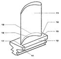
- FIG. 1 shows a turbine blade according to the prior art in a perspective view.
- Fig. 2 shows a schematic section through this blade immediately in the region of the transition from the Strömungsumschvortechnisch to the platform.
- FIG. 3 shows an analog section through a component with all features essential to the invention.
- Fig. 1 shows a flow machine component as carried out according to the prior art in a perspective view.
- the foot 12 of the component is provided with a device for attachment in the housing of a turbomachine or on its runners, as well as with a platform 15, on which the Strömungsumschvorides 11 is arranged.
- the platform is provided with a nose 14, which in the installed state with overlaps other components and has a sealing function.
- FIG. 2 A section through this flow machine component directly at the transition from the Strömungsumschvortechnisch to the platform is shown in Fig. 2, wherein the penetration line 18, 19 of the Strömungsumschvortechnisch 11 with the platform 15 can be seen particularly well.
- the disadvantageous stress conditions in this area are discussed in the introduction.
- cooling air channels can also be present within the blade.
- FIG. 3 shows a section analogous to that shown in FIG. 2, FIG. 3 showing a component according to the invention with all the features essential to the invention.
- the platform 15 is designed so that the leading edge base point 16 and the trailing edge base point 17 of the flow deflection device 11 lie exactly in corners of the parallelogram representing the platform in plan view.
- a platform edge forms a tangent to the suction-side profile line 19.
Landscapes
- Engineering & Computer Science (AREA)
- Physics & Mathematics (AREA)
- Fluid Mechanics (AREA)
- Mechanical Engineering (AREA)
- General Engineering & Computer Science (AREA)
- Structures Of Non-Positive Displacement Pumps (AREA)
- Turbine Rotor Nozzle Sealing (AREA)
Description
- Die Erfindung betrifft eine Komponente einer Strömungsmaschine, im wesentlichen bestehend aus einer Strömungsumlenkvorrichtung, welche in einem Fussbereich mit einer Plattform verbunden ist, wobei die Durchdringung der Strömungsumlenkvorrichtung mit der Plattform durch eine druckseitige Profillinie, eine saugseitige Profillinie, sowie einen Vorderkanten-Basispunkt und einen Hinterkanten-Basispunkt gegeben ist, und wobei die Draufsicht der Plattform im wesentlichen die Form eines Parallelogramms mit einer daran angeordneten in Umfangsrichtung verlaufenden Nase zeigt.
- Die Schaufeln moderner Gasturbinen unterliegen hohen mechanischen Belastungen aufgrund von Fliehkräften, aerodynamischen Kräften, und Wärmespannungen. Extrem hoch belastet ist insbesondere der Schaufelübergang, also der Bereich, in dem die eigentlichen Strömungsumlenkvorrichtungen in die Plattformen übergehen. An dieser Stelle muss das gesamte durch aerodynamische Kräfte induzierte Moment übertragen werden, und bei Laufschaufeln ist auch deren Fliehkraftbelastung zu halten. Bei hohen Heissgastemperaturen und insbesondere dann, wenn die Komponenten gekühlt werden, ist gerade im Bereich des Übergangs von der Schaufel zur Plattform weiterhin mit hohen Temperaturgradienten zu rechnen.
- In der Draufsicht stellen sich derartige Plattformen von Schaufeln meist als Parallelogramme dar, deren zwei Seiten in Umfangsrichtung der Maschine orientiert sind, während die beiden anderen Seiten in etwa in Richtung des mittleren Strömungswinkels verlaufen.
- Schaufeln, bei denen ein Schaufelblatt auf einem Schaufelfuss angeordnet ist, sind beispielsweise aus GB 2,162,588 oder US 5,443,365 bekannt.
- Meist ist an einem stromab gelegenen Ende eine in Umfangsrichtung verlaufende Nase angeordnet. Im eingebauten Zustand greifen die Nasen einer Plattform jeweils in eine korrespondierende Aussparung eines anderen Bauteils, und dichten so den Zwischenraum der Plattformen in Strömungsrichtung ab.
- Innerhalb der so beschriebenen Fläche liegt die Durchdringungslinie der Schaufel, die im wesentlichen durch eine saugseitige und druckseitige Profillinie sowie einen Hinterkanten-Basispunkt und einen Vorderkanten-Basispunkt zu charakterisieren ist. Die Plattformen tragen an ihrer Unterseite Vorrichtungen, um die Komponenten im Gehäuse oder auf der Welle zu verankern, und stellen daher recht massive und somit auch steife Gebilde dar.
- Der Fachmann erkennt bei der Draufsicht auf die so beschriebene Konfiguration im Übergang von der Strömungsumlenkvorrichtung zur Plattform die Grundzüge einer Dreipunktauflage, die das durch aerodynamische Kräfte induzierte Moment in die Plattform überträgt. Auflagepunkte sind hierbei die Basispunkte von Hinterkante und Vorderkante, sowie die saugseitige Profillinie, im Bereich der maximalen Wölbung.
- Aufgrund der Einleitung der Kräfte und Momente in die steife Plattform entstehen an den genannten Stellen komplexe dreidimensionale Spannungszustände. Aufgrund der Steifigkeit der Plattform kann das Material die Spannungen nicht durch elastische Dehnungen kompensieren; die erwähnten Temperaturgradienten bedingen Differenzdehnungen, die ebenfalls aufgrund der Bauteilgeometrie nicht frei erfolgen können, was die Bauteilbelastung weiter erhöht.
- Weiterhin müssen im Übergang von der Plattform zur Strömungsumlenkvorrichtung relativ enge Radien angebracht werden. Daraus resultiert in diesem Bereich eine Kerbwirkung und ein ungünstiger Kraftfluss.
- Insgesamt werden also starke Spannungen in einem Gebiet induziert, in dem die Werkstoffdehnung extrem behindert ist. Insbesondere, wenn die Festigkeit des Werkstoffs ohnehin durch hohe Temperaturen vermindert ist, begrenzen die auftretenden Spannungsspitzen die Lebensdauer einer Komponente.
- Hier will die Erfindung Abhilfe schaffen. Ziel der Erfindung ist es, bei einer Komponente einer Strömungsmaschine, im wesentlichen bestehend aus einer Strömungsumlenkvorrichtung, welche in einem Fussbereich mit einer Plattform verbunden ist, wobei die Durchdringung der Strömungsumlenkvorrichtung mit der Plattform durch eine druckseitige Profillinie, eine saugseitige Profillinie, sowie einen Vorderkanten-Basispunkt und einen Hinterkanten-Basispunkt gegeben ist, und wobei die Draufsicht der Plattform im wesentlichen die Form eines Parallelogramms mit einer daran angeordneten in Umfangsrichtung verlaufenden Nase zeigt den Übergang von der Plattform zu der Strömungsumlenkvorrichtung derart zu gestalten, dass die einleitend genannten Spannungsüberhöhungen soweit als möglich vermieden werden. Insbesondere ist die Kontur der Komponente im Bereich des Übergangs von der Plattform zur Strömungsumlenkvorrichtung entsprechend zu gestalten, Erfindungsgemäss wird dies einerseits dadurch erreicht, dass die Hinterkanten-Verlaufslinie der Strömungsumlenkvorrichtung in einer Ecke des Parallelogramms liegt.
- Es ist ebenso im Sinne der Erfindung möglich, dass die Vorderkanten-Verlaufslinie der Strömungsumlenkvorrichtung in einer Ecke des Parallelogramms liegt, oder, dass eine Parallelogramm-Längsseite als Tangente zur saugseitigen Profilline angeordnet ist. Alle drei Merkmale können beliebig untereinander kombiniert werden.
- Insbesondere in Verbindung mit der Plazierung des Hinterkanten-Basispunktes ist es von Vorteil, wenn die Nase der Plattform am stromabwärtigen Ende der saugseitigen Parallelogramm-Längsseite der Plattform angeordnet ist.
- Nachfolgend sei die Erfindung anhand der Zeichnung näher erläutert. Dabei zeigt Fig. 1 eine Turbinenschaufel nach dem Stand der Technik in perspektivischer Darstellung. Fig. 2 zeigt einen schematischen Schnitt durch diese Schaufel unmittelbar im Bereich des Übergangs von der Strömungsumlenkvorrichtung zur Plattform. Fig. 3 schliesslich zeigt einen analogen Schnitt durch eine Komponente mit allen erfindungswesentlichen Merkmalen.
- Fig. 1 zeigt eine Strömungsmaschinenkomponente wie sie nach dem Stand der Technik ausgeführt wird in perspektivischer Darstellung. Der Fuss 12 der Komponente ist mit einer Vorrichtung zur Befestigung im Gehäuse einer Strömungsmaschine oder auf deren Läufer versehen, sowie mit einer Plattform 15, auf welcher die Strömungsumlenkvorrichtung 11 angeordnet ist. Im Bereich des Übergangs von der Strömungsumlenkvorrichtung zum Fuss finden sich eine druckseitige Profillinie 18, eine saugseitige Profillinie 19, sowie jeweils ein Basispunkt der Vorderkante und der Hinterkante, 16 bzw. 17. Die Plattform ist mit einer Nase 14 versehen, welche im eingebauten Zustand mit anderen Bauteilen überlappt und eine Dichtfunktion hat.
- Ein Schnitt durch diese Strömungsmaschinenkomponente unmittelbar am Übergang von der Strömungsumlenkvorrichtung zur Plattform ist in Fig. 2 dargestellt, wobei die Durchdringungslinie 18, 19 der Strömungsumlenkvorrichtung 11 mit der Plattform 15 besonders gut zu erkennen ist. Die nachteiligen Spannungsverhältnisse in diesem Bereich sind einleitend diskutiert.
- Zu erwähnen ist an dieser Stelle, dass die Darstellung der Schaufeln als Vollprofile in den Figuren 2 und 3 rein schematischer Natur ist, und nicht in einem einschränkenden Sinne verstanden werden darf. Innerhalb der Schaufel können beispielsweise auch Kühlluftkanäle vorhanden sein.
- In Fig. 3 ist ein Schnitt analog zum dem in Fig. 2 dargestellten abgebildet, wobei Fig. 3 eine erfindungsgemässe Komponente mit allen erfindungswesentlichen Merkmalen darstellt. Die Plattform 15 ist so gestaltet, dass der Vorderkanten-Basispunkt 16 und der Hinterkanten-Basispunkt 17 der Strömungsumlenkvorrichtung 11 genau in Ecken des Parallelogramms, welches die Plattform in der Draufsicht darstellt, liegen. Eine Plattformkante bildet eine Tangente zur saugseitigen Profillinie 19. Wie der Fachmann leicht erkennt, ergibt sich durch diese Massnahmen ein wesentlich günstigerer Kraftfluss an den Stellen, an denen, wie einleitend diskutiert, die höchsten Spannungen vorliegen. Dadurch, dass diese Bereiche der Strömumgsumlenkvorrichtung an der Aussenseite der Plattform enden, werden an diesen Stellen die Verformungen des Werkstoffs weniger behindert als bei einer herkömmlichen Ausgestaltung. Gerade an den Stellen maximaler Belastung geht die Plattform geradlinig in die Strömungsumlenkvorrichtung über und der Kraftfluss muss nicht umgelenkt werden. Spannungsspitzen werden hierdurch wesentlich besser durch elastische Dehnungen aufgenommen und Spannungsüberhöhungen vermieden.
- Im Rahmen der Implementation der erfindungsgemässen Merkmale ist es weiterhin vorteilhaft, die Nase 14 auf der Saugseite anzubringen. Es wird dadurch konstruktiv wesentlich einfacher, den Hinterkanten-Basispunkt erfindungsgemäss anzuordnen.
-
- 11
- Strömungsumlenkvorrichtung
- 12
- Fuss
- 14
- Nase
- 15
- Plattform
- 16
- Vorderkanten-Basispunkt
- 17
- Hinterkanten-Basispunkt
- 18
- druckseitige Profillinie
- 19
- saugseitige Profillinie
Claims (5)
- Komponente einer Strömungsmaschine, im wesentlichen bestehend aus einer Strömungsumlenkvorrichtung (11), welche in einem Fussbereich mit einer Plattform (15) verbunden ist, wobei die Durchdringung der Strömungsumlenkvorrichtung mit der Plattform durch eine druckseitige Profillinie (18), eine saugseitige Profillinie (19), sowie eine Vorderkanten-Verlaufslinie (16) und eine Hinterkanten Verlaufslinie (17) gegeben ist, und wobei die Draufsicht der Plattform im wesentlichen die Form eines Parallelogramms mit einer daran angeordneten in Umfangsrichtung verlaufenden Nase (14) zeigt, dadurch gekennzeichnet, dass die Hinterkanten Verlaufslinie der Strömungsumlenkvorrichtung in einem von zwei Seiten des Parallelogramms gebildeten Winkel einbeschrieben ist.
- Komponente gemäss Auspruch 1 dadurch gekennzeichnet, dass die Vorderkanten Verlaufslinie Strömungsumlenkvorrichtung in einem von zwei Seiten des Parallelogramms gebildeten Winkel einbeschrieben ist.
- Komponente gemäss einem der vorstehenden Ausprüche dadurch gekennzeichnet, dass eine Parallelogramm-Längsseite alsTangente zur saugseitigen Profilline angeordnet ist.
- Komponente einer Strömungsmaschine nach einem der Ansprüche 1 bis 3, dadurch gekennzeichnet, dass die Nase am stromabwärtigen Ende der saugseitigen Parallelogramm-Längsseite der Plattform angeordnet ist
- Komponente gemäss einem der vorstehenden Ansprüche, dadurch gekennzeichnet, dass die Geometrien der Strömungsumlenkvorrichtung (11) und der Plattform (15) so aufeinander abgestimmt sind, dass die Durchdringung der Strömungsumlenkvorrichtung mit der Plattform von dem Parallelogramm umbeschrieben ist.
Priority Applications (3)
| Application Number | Priority Date | Filing Date | Title |
|---|---|---|---|
| DE59912578T DE59912578D1 (de) | 1999-02-10 | 1999-02-10 | Turbomaschinenschaufel |
| EP99810111A EP1028229B1 (de) | 1999-02-10 | 1999-02-10 | Turbomaschinenschaufel |
| US09/499,399 US6343914B1 (en) | 1999-02-10 | 2000-02-07 | Fluid-flow machine component |
Applications Claiming Priority (1)
| Application Number | Priority Date | Filing Date | Title |
|---|---|---|---|
| EP99810111A EP1028229B1 (de) | 1999-02-10 | 1999-02-10 | Turbomaschinenschaufel |
Publications (2)
| Publication Number | Publication Date |
|---|---|
| EP1028229A1 EP1028229A1 (de) | 2000-08-16 |
| EP1028229B1 true EP1028229B1 (de) | 2005-09-21 |
Family
ID=8242671
Family Applications (1)
| Application Number | Title | Priority Date | Filing Date |
|---|---|---|---|
| EP99810111A Expired - Lifetime EP1028229B1 (de) | 1999-02-10 | 1999-02-10 | Turbomaschinenschaufel |
Country Status (3)
| Country | Link |
|---|---|
| US (1) | US6343914B1 (de) |
| EP (1) | EP1028229B1 (de) |
| DE (1) | DE59912578D1 (de) |
Families Citing this family (2)
| Publication number | Priority date | Publication date | Assignee | Title |
|---|---|---|---|---|
| JP5090287B2 (ja) * | 2008-08-07 | 2012-12-05 | 株式会社日立製作所 | タービン動翼とその固定構造 |
| CH700319A1 (de) * | 2009-01-30 | 2010-07-30 | Alstom Technology Ltd | Gekühltes bauelement für eine gasturbine. |
Family Cites Families (8)
| Publication number | Priority date | Publication date | Assignee | Title |
|---|---|---|---|---|
| US3014695A (en) * | 1960-02-03 | 1961-12-26 | Gen Electric | Turbine bucket retaining means |
| GB2162588B (en) * | 1984-07-30 | 1988-11-09 | Gen Electric | Gas turbine bladed disk assembly |
| US4676723A (en) * | 1986-03-26 | 1987-06-30 | Westinghouse Electric Corp. | Locking system for a turbine side entry blade |
| US4815938A (en) * | 1987-12-24 | 1989-03-28 | Westinghouse Electric Corp. | Shroud gap control for integral shrouded blades |
| JPH06129203A (ja) * | 1992-10-09 | 1994-05-10 | Mitsubishi Heavy Ind Ltd | ガスタービン動翼の防振構造 |
| US5443365A (en) * | 1993-12-02 | 1995-08-22 | General Electric Company | Fan blade for blade-out protection |
| FR2743845B1 (fr) * | 1996-01-23 | 1998-02-20 | Snecma | Aube mobile de soufflante a profil de securite |
| US6030178A (en) * | 1998-09-14 | 2000-02-29 | General Electric Co. | Axial entry dovetail segment for securing a closure bucket to a turbine wheel and methods of installation |
-
1999
- 1999-02-10 EP EP99810111A patent/EP1028229B1/de not_active Expired - Lifetime
- 1999-02-10 DE DE59912578T patent/DE59912578D1/de not_active Expired - Lifetime
-
2000
- 2000-02-07 US US09/499,399 patent/US6343914B1/en not_active Expired - Lifetime
Also Published As
| Publication number | Publication date |
|---|---|
| DE59912578D1 (de) | 2005-10-27 |
| EP1028229A1 (de) | 2000-08-16 |
| US6343914B1 (en) | 2002-02-05 |
Similar Documents
| Publication | Publication Date | Title |
|---|---|---|
| EP1439281B1 (de) | Fanschaufel für ein Gasturbinentriebwerk | |
| DE602004001531T2 (de) | Statorschaufel mit Doppelkrümmung | |
| EP2462320B1 (de) | Schaufelblatt | |
| EP1163425B1 (de) | Turbinenschaufel | |
| EP1447524B1 (de) | Hybrid-Schaufel für thermische Turbomaschinen | |
| DE102009013399A1 (de) | Tandemschaufelkonstruktion | |
| EP2644829A1 (de) | Turbinenschaufel | |
| EP0825332B1 (de) | Kühlbare Schaufel | |
| DE102017218886A1 (de) | Schaufel und Rotor für eine Strömungsmaschine sowie Strömungsmaschine | |
| DE2639200A1 (de) | Laufrad fuer axialturbinen, insbesondere fuer gasturbinen | |
| DE602004007071T2 (de) | Zwischenschaufelplattformen mit elastischen Seitenkanten | |
| DE112013002712T5 (de) | Turbinendämpfer | |
| DE3835622A1 (de) | Radialverdichter | |
| DE2944987C3 (de) | Laufschaufel für Dampfturbinen | |
| WO2017005484A1 (de) | Turbinenschaufel | |
| EP1028229B1 (de) | Turbomaschinenschaufel | |
| DE102009007664A1 (de) | Abdichtvorrichtung an dem Schaufelschaft einer Rotorstufe einer axialen Strömungsmaschine | |
| EP3109520B1 (de) | Dichtungsträger, leitschaufelkranz und strömungsmaschine | |
| WO2013144270A1 (de) | Modulare turbinenschaufel mit plattform | |
| WO2015063021A1 (de) | Turbinenschaufel mit einer mittigen ausblasung an der hinterkante | |
| EP3460187A1 (de) | Schaufel für eine strömungsmaschine | |
| EP1163426A1 (de) | Turbomaschinenschaufel | |
| EP1524407B1 (de) | Hohlfanschaufel für Flugzeugtriebwerke und Verfahren zu deren Herstellung | |
| EP2860352A1 (de) | Rotor, zugehöriges Herstellungsverfahren und Laufschaufel | |
| EP1355041A2 (de) | Turbinenschaufel |
Legal Events
| Date | Code | Title | Description |
|---|---|---|---|
| PUAI | Public reference made under article 153(3) epc to a published international application that has entered the european phase |
Free format text: ORIGINAL CODE: 0009012 |
|
| AK | Designated contracting states |
Kind code of ref document: A1 Designated state(s): DE GB |
|
| AX | Request for extension of the european patent |
Free format text: AL;LT;LV;MK;RO;SI |
|
| 17P | Request for examination filed |
Effective date: 20010116 |
|
| RAP1 | Party data changed (applicant data changed or rights of an application transferred) |
Owner name: ALSTOM POWER (SCHWEIZ) AG |
|
| AKX | Designation fees paid |
Free format text: DE GB |
|
| RAP1 | Party data changed (applicant data changed or rights of an application transferred) |
Owner name: ALSTOM |
|
| RAP1 | Party data changed (applicant data changed or rights of an application transferred) |
Owner name: ALSTOM (SWITZERLAND) LTD |
|
| 17Q | First examination report despatched |
Effective date: 20030131 |
|
| RAP1 | Party data changed (applicant data changed or rights of an application transferred) |
Owner name: ALSTOM TECHNOLOGY LTD |
|
| GRAP | Despatch of communication of intention to grant a patent |
Free format text: ORIGINAL CODE: EPIDOSNIGR1 |
|
| GRAS | Grant fee paid |
Free format text: ORIGINAL CODE: EPIDOSNIGR3 |
|
| GRAA | (expected) grant |
Free format text: ORIGINAL CODE: 0009210 |
|
| AK | Designated contracting states |
Kind code of ref document: B1 Designated state(s): DE GB |
|
| REG | Reference to a national code |
Ref country code: GB Ref legal event code: FG4D Free format text: NOT ENGLISH |
|
| REF | Corresponds to: |
Ref document number: 59912578 Country of ref document: DE Date of ref document: 20051027 Kind code of ref document: P |
|
| GBT | Gb: translation of ep patent filed (gb section 77(6)(a)/1977) |
Effective date: 20051205 |
|
| PLBE | No opposition filed within time limit |
Free format text: ORIGINAL CODE: 0009261 |
|
| STAA | Information on the status of an ep patent application or granted ep patent |
Free format text: STATUS: NO OPPOSITION FILED WITHIN TIME LIMIT |
|
| 26N | No opposition filed |
Effective date: 20060622 |
|
| REG | Reference to a national code |
Ref country code: DE Ref legal event code: R082 Ref document number: 59912578 Country of ref document: DE Representative=s name: ROESLER, UWE, DIPL.-PHYS.UNIV., DE Ref country code: DE Ref legal event code: R081 Ref document number: 59912578 Country of ref document: DE Owner name: ANSALDO ENERGIA IP UK LIMITED, GB Free format text: FORMER OWNER: ALSTOM TECHNOLOGY LTD., BADEN, CH Ref country code: DE Ref legal event code: R081 Ref document number: 59912578 Country of ref document: DE Owner name: GENERAL ELECTRIC TECHNOLOGY GMBH, CH Free format text: FORMER OWNER: ALSTOM TECHNOLOGY LTD., BADEN, CH |
|
| PGFP | Annual fee paid to national office [announced via postgrant information from national office to epo] |
Ref country code: DE Payment date: 20170217 Year of fee payment: 19 |
|
| PGFP | Annual fee paid to national office [announced via postgrant information from national office to epo] |
Ref country code: GB Payment date: 20170216 Year of fee payment: 19 |
|
| REG | Reference to a national code |
Ref country code: DE Ref legal event code: R082 Ref document number: 59912578 Country of ref document: DE Representative=s name: ROESLER, UWE, DIPL.-PHYS.UNIV., DE Ref country code: DE Ref legal event code: R081 Ref document number: 59912578 Country of ref document: DE Owner name: ANSALDO ENERGIA IP UK LIMITED, GB Free format text: FORMER OWNER: GENERAL ELECTRIC TECHNOLOGY GMBH, BADEN, CH |
|
| REG | Reference to a national code |
Ref country code: GB Ref legal event code: 732E Free format text: REGISTERED BETWEEN 20170824 AND 20170830 |
|
| REG | Reference to a national code |
Ref country code: DE Ref legal event code: R119 Ref document number: 59912578 Country of ref document: DE |
|
| GBPC | Gb: european patent ceased through non-payment of renewal fee |
Effective date: 20180210 |
|
| PG25 | Lapsed in a contracting state [announced via postgrant information from national office to epo] |
Ref country code: DE Free format text: LAPSE BECAUSE OF NON-PAYMENT OF DUE FEES Effective date: 20180901 |
|
| PG25 | Lapsed in a contracting state [announced via postgrant information from national office to epo] |
Ref country code: GB Free format text: LAPSE BECAUSE OF NON-PAYMENT OF DUE FEES Effective date: 20180210 |