EP1028492A1 - Elément de connexion - Google Patents
Elément de connexion Download PDFInfo
- Publication number
- EP1028492A1 EP1028492A1 EP00102584A EP00102584A EP1028492A1 EP 1028492 A1 EP1028492 A1 EP 1028492A1 EP 00102584 A EP00102584 A EP 00102584A EP 00102584 A EP00102584 A EP 00102584A EP 1028492 A1 EP1028492 A1 EP 1028492A1
- Authority
- EP
- European Patent Office
- Prior art keywords
- connecting element
- strip
- clamping
- connection
- approximately
- Prior art date
- Legal status (The legal status is an assumption and is not a legal conclusion. Google has not performed a legal analysis and makes no representation as to the accuracy of the status listed.)
- Withdrawn
Links
- 238000004519 manufacturing process Methods 0.000 claims abstract description 14
- 238000000034 method Methods 0.000 claims description 16
- 230000008878 coupling Effects 0.000 claims description 13
- 238000010168 coupling process Methods 0.000 claims description 13
- 238000005859 coupling reaction Methods 0.000 claims description 13
- 230000008569 process Effects 0.000 claims description 12
- 230000007704 transition Effects 0.000 claims description 10
- 238000002788 crimping Methods 0.000 claims description 6
- 238000000748 compression moulding Methods 0.000 claims description 4
- 238000005476 soldering Methods 0.000 claims description 4
- 238000005520 cutting process Methods 0.000 claims description 3
- 238000003466 welding Methods 0.000 claims description 3
- 238000000465 moulding Methods 0.000 claims 1
- 239000004020 conductor Substances 0.000 abstract description 10
- 239000002184 metal Substances 0.000 abstract 1
- 239000000463 material Substances 0.000 description 7
- 238000005452 bending Methods 0.000 description 5
- 238000004080 punching Methods 0.000 description 5
- 230000008901 benefit Effects 0.000 description 2
- 238000009826 distribution Methods 0.000 description 2
- 238000000926 separation method Methods 0.000 description 2
- RYGMFSIKBFXOCR-UHFFFAOYSA-N Copper Chemical compound [Cu] RYGMFSIKBFXOCR-UHFFFAOYSA-N 0.000 description 1
- 238000010276 construction Methods 0.000 description 1
- 239000000109 continuous material Substances 0.000 description 1
- 229910052802 copper Inorganic materials 0.000 description 1
- 239000010949 copper Substances 0.000 description 1
- 238000005304 joining Methods 0.000 description 1
- 230000009467 reduction Effects 0.000 description 1
- 238000007493 shaping process Methods 0.000 description 1
- 239000007858 starting material Substances 0.000 description 1
- 238000003860 storage Methods 0.000 description 1
Images


Classifications
-
- H—ELECTRICITY
- H01—ELECTRIC ELEMENTS
- H01H—ELECTRIC SWITCHES; RELAYS; SELECTORS; EMERGENCY PROTECTIVE DEVICES
- H01H85/00—Protective devices in which the current flows through a part of fusible material and this current is interrupted by displacement of the fusible material when this current becomes excessive
- H01H85/02—Details
- H01H85/20—Bases for supporting the fuse; Separate parts thereof
- H01H85/203—Bases for supporting the fuse; Separate parts thereof for fuses with blade type terminals
- H01H85/2035—Bases for supporting the fuse; Separate parts thereof for fuses with blade type terminals for miniature fuses with parallel side contacts
-
- H—ELECTRICITY
- H01—ELECTRIC ELEMENTS
- H01R—ELECTRICALLY-CONDUCTIVE CONNECTIONS; STRUCTURAL ASSOCIATIONS OF A PLURALITY OF MUTUALLY-INSULATED ELECTRICAL CONNECTING ELEMENTS; COUPLING DEVICES; CURRENT COLLECTORS
- H01R13/00—Details of coupling devices of the kinds covered by groups H01R12/70 or H01R24/00 - H01R33/00
- H01R13/02—Contact members
- H01R13/10—Sockets for co-operation with pins or blades
- H01R13/11—Resilient sockets
-
- H—ELECTRICITY
- H01—ELECTRIC ELEMENTS
- H01R—ELECTRICALLY-CONDUCTIVE CONNECTIONS; STRUCTURAL ASSOCIATIONS OF A PLURALITY OF MUTUALLY-INSULATED ELECTRICAL CONNECTING ELEMENTS; COUPLING DEVICES; CURRENT COLLECTORS
- H01R43/00—Apparatus or processes specially adapted for manufacturing, assembling, maintaining, or repairing of line connectors or current collectors or for joining electric conductors
- H01R43/16—Apparatus or processes specially adapted for manufacturing, assembling, maintaining, or repairing of line connectors or current collectors or for joining electric conductors for manufacturing contact members, e.g. by punching and by bending
-
- H—ELECTRICITY
- H01—ELECTRIC ELEMENTS
- H01H—ELECTRIC SWITCHES; RELAYS; SELECTORS; EMERGENCY PROTECTIVE DEVICES
- H01H85/00—Protective devices in which the current flows through a part of fusible material and this current is interrupted by displacement of the fusible material when this current becomes excessive
- H01H85/02—Details
- H01H85/20—Bases for supporting the fuse; Separate parts thereof
- H01H2085/2085—Holders for mounting a fuse on a printed circuit
Definitions
- the invention relates to a connecting element for the production of electrical Connections between electrical components, especially relays or fuses, and connecting cables in motor vehicles.
- Such connecting elements are used, for example, in motor vehicles in addition, single fuses or multiple connections fuse units to be connected to connecting cables at fuse boxes, either in the form of cables or wires or in the form of on printed circuit boards or printed circuit boards.
- the connecting element as one piece Stamped / bent part is formed and at least one clamping receptacle for an electrical component and at least one with at least one connecting line connectable support section for the clamp receptacle comprises, the distance between the mutually facing inner sides of the clamping arms forming the clamping receptacle in the area of a common base section of mine is closer to the free than in one End of the clamping arms located area.
- the connecting element in the receiving area contact connections between the clamping arms of the clamping receptacle of the electrical components are inserted during the carrier section for the electrical contact with the respective connecting cable worries.
- the design as a stamped / bent part enables simple and fast automated production of the connecting element.
- the provision of a compared to the conditions at the recording area My distance between the clamp arms in the area of the common Base section allows the clamping arms to lie close together to punch out the starting material so that little material is needed.
- the one for receiving the contact connections of the electrical Components required greater distance in the recording area can by appropriate shaping of the clamping arms following the Punching process can be obtained.
- the invention is particularly advantageous when many fasteners are punched out of a continuous strip of material because there is a larger number of connecting elements per unit length can be obtained.
- the base section as on both sides approximately perpendicular outgoing from the one clamping arm Connection strips formed, each at its free ends one of two together forming the other clamp arm and preferably arm sections running approximately perpendicular to the connecting strip wearing.
- the carrier section is designed as a carrier strip, with at least a strip edge a plurality of preferably evenly spaced Clamping shots are preferably approximately perpendicular to the longitudinal axis of the strip stand out.
- Connecting element is that it is an endless strip is producible, which is wound into a supply roll and thus special can be stored and transported easily. For the production the electrical connections can then have a connecting element the required length or the required number of clamp receptacles be unwound from the supply roll and cut off.
- a connecting element according to the invention having a plurality of clamping receptacles is also used as a female terminal busbar, i.e. as a stripe Plug-in bus referred to, in which the power distribution on or from the individual clamp recordings via the common carrier strip he follows.
- the carrier strip can engage a separate connection element brought, which for electrical connection with, for example In the form of cables or wires existing connecting lines is used.
- the connecting element can also be a one-piece stamped / bent part be formed and for example by a clinching process with the Carrier strips are connected.
- the connecting element is preferably designed such that it is approximately Exit direction running parallel to the carrier strip of the connecting element for the connecting line or connecting lines. This advantageously enables a low construction.
- the connecting element can be in the form of an endless strip with one longitudinally repeating basic structure are produced, so that it is easily wound, stored and stored in a supply roll can be transported.
- each formed by an endless strip Supply roll a connecting element and a connecting element with the desired length is cut off and a coupling strip of the connecting element and a carrier strip of the connecting element with each other be engaged.
- both the cutting operations and the connection of Connection element and connecting element automatically and in one Machine.
- connection element which can be brought into engagement with the carrier strip
- the carrier strip with a printed circuit board, e.g. a fuse box to connect, for example in the terminal receptacles the connecting element plug-in fuses to one or more Connect conductor tracks.
- each associated with a clamping receptacle Contact protrusion protrudes.
- the connecting element can then with the contact projections in corresponding openings the board is inserted and soldered so that between the conductor tracks electrical connections on the circuit board and the clamp receptacles over the remaining one, also referred to below as the main strip Part of the carrier strip exist.
- the contact projections in one of their free end distant area are provided with an extension.
- This extension can be designed so that it is plugged onto a circuit board Connection element with the extensions on the circuit board. If, according to a preferred variant, the contact projections of one and the clamp recordings from the opposite strip edge stick out of the remaining main strip, then the main strip forms between the extensions of the contact projections bridges, under which conductor tracks can be passed, their contacting with the connecting element is not desired.
- Fig. 1 shows an embodiment of a connecting element according to the invention 10 in the punched and not yet bent state, in which it is still connected to a production strip 60 '.
- the connecting element 10 are separated from the production strip 16 'to individual connecting elements 10 to be obtained, which are shown in FIGS. 2 and 3 and described below.
- the punch can also be used in this way be formed so that the connecting element 10 before disconnection on one of the plug-in sections 27 or the contact pin explained below 23 is connected to the production strip 16 '.
- the connector 10 can be separated from a variety are obtained from endless strips having clamping receptacles, as he e.g. hereinafter in connection with FIGS. 4 and 5 or with 6 and 7 will be described.
- the connecting element 10 comprises a strip-shaped rectangular Clamping arm 20 and two strip-shaped clamping arm sections 18a and 18b, which together in the bent state of the connecting element 10 form a further clamping arm 18, which together with the Clamping arm 20 a clamping receptacle of the connecting element 10 for electrical contacts of electrical components, for example fuses, forms.
- the clamp arm 20 and the clamp arm sections 18a, 18b are in one common connecting strip 22 attached, from which they are each extend vertically.
- the distance a between the clamping arm 20 and the two clamp arm portions 18a, 18b is smaller than that, respectively Width of the clamping arm 20 and slightly larger than the width of the Clamp arm sections 18a, 18b.
- the distance a ' can also be smaller than that Width of the clamping arm sections 18a, 18b can be selected.
- clamping arm sections 18a, 18b are each with bevelled 19, which is preceded by an extension 21, from which the distance to the clamping arm 20 is smaller than the distance a ' in the region of a base section of the connecting element 10 Connecting strip 22 is.
- one of the plug-in sections 27 carries at its free end a contact pin 23.
- the connecting element 10 e.g. in a plastic housing be pressed in while it is made with such a Protruding contact pin 23 in a corresponding opening e.g. can be plugged into a circuit board or circuit board and soldered.
- Fig. 2 shows a side view of that separated from the production strip 16 ' Connecting element 10 in the final state, in which on the one hand the two Clamp arm sections 18a and 18b about 90 ° around the clamp arm 20 are bent around and on the other hand the clamping arm 20 approximately in one S shape is curved.
- Fig. 2 shows that that formed by the two clamping arm sections 18a, 18b Clamp arm 18 of the connecting element 10 according to the invention runs straight, while through the S-shape of the other clamping arm 20th created a clamp receptacle 14 with areas of different widths becomes.
- the clamping arm 20 runs in a straight line away from the other clamping arm 18 up to a first transition section 26, on which the clamping arm 20 is angled. From the first transition section 26 to a second, along with the other Clamping arm 18 forms a transition section in FIG Height of the extensions 21, the clamp arm 20 is straight and obliquely towards the clamping arm 18. From the clamping area 28 to his The free end of the clamping arm 20 in turn extends straight from the other Clamping arm 18 away so that it can be slanted together with the free ends of the clamping arm sections 18a, 18b a V-shaped receptacle forms.
- connection element 10 would correspond to the invention saved more than 20% in material.
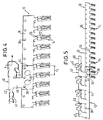
- Fig. 4 shows a connection arrangement according to the invention, the connection element 10 and a connecting element 40 comprises. Both that Connecting element 10 and the connecting element 40 are made of one Continuous material stiffening with a repeating in the longitudinal direction Basic structure made.
- the carrier section of the connecting element 10 is supported by a carrier strip 16 formed in which positioning holes 36 for alignment with the connection element also having positioning holes 40 are provided.
- a variety of clamp receptacles 14 are like that Prongs of a comb from a side edge of the carrier strip 16 over Web 39 from that with the connecting strip 22 of the clamping receptacles 14 are connected. Different from the connecting element shown in FIG. 1 the webs 39 each extend one of the Clamping arm sections, i.e. the webs are attached laterally.
- the connecting element 40 comprises a coupling strip 44 for connection with the carrier strip 16 and a connecting strip 42 for connection to connecting lines, not shown.
- Deformations 38 indicate in Fig. 4 indicates that the coupling strip 44 and the carrier strip 16 by one Compression molding or clinching are brought into engagement with one another, the ones formed in the coupling strip 44 and in the carrier strip 16 Positioning holes 36 make it easy for the correct relative position between connecting element 10 and connecting element 40 to worry about.
- the connection between connecting element 10 and Connection element 40 can also be made by soldering or welding. In the assembled state according to FIG. 4, the connecting strips run 42 and the coupling strip 44 each parallel to the carrier strip 16, so that a departure direction indicated in Fig. 4 by the arrow K set for the connecting line parallel to the carrier strip 16 is.
- connection strips 42 and coupling strips 44 which in this embodiment are shorter than the clamp receptacles 14, a low height perpendicular to the individual strips 16, 42, 44 can be achieved.
- the connection between a connecting line and the connecting strip 42 takes place in a crimping or crimping process with the aid of tabs 41, 4 that the connecting strip 42 is trough-shaped is pre-bent to make it easy to pre-position the connecting cable enable.
- each of a supply roll to which both Connecting element 10 and the connecting element 40 after the Stamping and bending into the final shape for storage and Transport wrapped, the required length unwound, whereupon a single connecting element 10 and a single connecting element 40 can be cut to the desired length.
- connection arrangement according to the invention is shown in 5 indicated in the two connecting elements separated by a cut 50 10 can be seen, of which one six and the other has another ten clamp receptacles 14.
- connection elements 40 In the endless strip from which connection elements 40 are cut, can the terminal strip 42 already during the manufacture of the Endless strip e.g. be provided with cutting points 62 during punching, which separate connecting elements 40, which only later to Connect with individual connecting elements 10 by cuts 50 in Coupling strips 40 are finally separated from each other.
- 5 is also a connecting line to be connected to a connecting strip 42 60 shown.
- connection element 40 and Connection line 60 are preferably carried out automatically on a single machine. It is also possible to use such connecting elements 40 with connecting elements 10 bring into engagement, which in advance with connecting lines 60 have been connected.
- FIG. 6 shows a connecting element 10 according to a further embodiment of the invention, which is the manufacture of another, hereinafter in connection with FIGS. 8 and 9 described connection arrangement allows the connection elements as described above were not required.
- FIG. 7 shows the connecting element 10 according to the invention from FIG. 6 in an enlarged view and from a different direction, wherein in particular the contact projections 32 can be seen, the one T-shape with a comparatively wide central beam and one of the Extension 33 formed crossbar. From Fig. 7 is further the lateral attachment of an extension of the clamping arm sections 18a webs 39 can be seen.
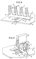
- the connecting element shown in FIGS. 6 and 7 can 10 can also be connected to a printed circuit board 70 the connecting lines to be contacted with the connecting element 10 60 and further lines 61 each in the form of conductor tracks are.
- the ones that form the T center bar are shown in FIG. 8 and FIG. 9 sections of the contact projections which cannot be seen corresponding openings are inserted in the circuit board 70, these openings are dimensioned such that the connecting element 10 with the Extensions 33 rests on the circuit board 70. Electrical connections to the conductor tracks running in the area of the contact projections 60 can be made by soldering.
- connecting element 10 with the extensions 33 on the circuit board 70 can through the gap between the circuit board 70 and that between two successive extensions 33 extending region of the main strip 17 such conductor tracks 61 are passed, which are not with the connecting element 10 should be contacted.
- connecting element 10 allows the use of a circuit board 70 which is low Has copper layer thickness, since the main current distribution through the Main strip 17 takes place and the circuit board 70 is not loaded.
- By the use of such inexpensive circuit boards 70 can be significant Cost reduction can be achieved.
- FIG. 9 shows how an electrical component 12, for example a fuse, via two connecting elements 10 according to the invention with a printed circuit board 70 can be connected.
- the right connecting element in FIG. 9 10 is provided with a plurality of clamping receptacles 14, of which only one of a plug contact 13 of the fuse 12 is used.
- a second plug contact 13 of the fuse 12 is in the terminal receptacle of a further connecting element 10, the clamp receptacle not one of many, from a common carrier strip outgoing terminal recordings, but as a separate connecting element 10 corresponding to the embodiment shown in FIGS. 2 and 3 the invention is formed.
- With its support section 16 is the connector 10 in the circuit board 70 to which it is Contacting with the desired conductor track are soldered can.
- the individual connecting element 10 can advantageously by Disconnect from a plurality of clamping receptacles 14 Continuous strips can be obtained, e.g. shown in Figs. 6 and 7 , being as the carrier section to be inserted into a printed circuit board 70 the contact protrusion 32 serves.
Landscapes
- Engineering & Computer Science (AREA)
- Manufacturing & Machinery (AREA)
- Manufacturing Of Electrical Connectors (AREA)
Applications Claiming Priority (2)
| Application Number | Priority Date | Filing Date | Title |
|---|---|---|---|
| DE19905717 | 1999-02-11 | ||
| DE1999105717 DE19905717A1 (de) | 1999-02-11 | 1999-02-11 | Verbindungselement |
Publications (1)
| Publication Number | Publication Date |
|---|---|
| EP1028492A1 true EP1028492A1 (fr) | 2000-08-16 |
Family
ID=7897187
Family Applications (1)
| Application Number | Title | Priority Date | Filing Date |
|---|---|---|---|
| EP00102584A Withdrawn EP1028492A1 (fr) | 1999-02-11 | 2000-02-07 | Elément de connexion |
Country Status (2)
| Country | Link |
|---|---|
| EP (1) | EP1028492A1 (fr) |
| DE (1) | DE19905717A1 (fr) |
Cited By (2)
| Publication number | Priority date | Publication date | Assignee | Title |
|---|---|---|---|---|
| DE202004002643U1 (de) * | 2004-02-18 | 2005-07-07 | Lear Corporation Electrical And Electronics Gmbh & Co. Kg | Elektrisches Kontaktelement |
| DE102004054678A1 (de) * | 2004-11-12 | 2006-05-24 | William Prym Gmbh & Co. Kg | Einstückiges Gegenkontaktelement für einen elektrischen Flachstecker |
Families Citing this family (2)
| Publication number | Priority date | Publication date | Assignee | Title |
|---|---|---|---|---|
| DE102008005078B3 (de) * | 2008-01-18 | 2009-06-10 | Audi Ag | Strombrücke mit mehreren Kontaktebenen |
| DE102009006134B4 (de) | 2009-01-26 | 2017-12-07 | Lear Corp. | Sicherungskasten und Sammelschiene für einen Sicherungskasten |
Citations (3)
| Publication number | Priority date | Publication date | Assignee | Title |
|---|---|---|---|---|
| US3823392A (en) * | 1972-09-05 | 1974-07-09 | Heyman Mfg Co | Female contact blade |
| US4007977A (en) * | 1974-05-09 | 1977-02-15 | Bunker Ramo Corporation | Electrical connector |
| DE19618496A1 (de) * | 1996-05-08 | 1997-11-20 | Whitaker Corp | Elektrisches Kontaktelement zur Kontaktierung eines Flachkontaktes |
Family Cites Families (1)
| Publication number | Priority date | Publication date | Assignee | Title |
|---|---|---|---|---|
| GB8826969D0 (en) * | 1988-11-18 | 1988-12-21 | Thomas & Betts Corp | Improvements in contacts |
-
1999
- 1999-02-11 DE DE1999105717 patent/DE19905717A1/de not_active Withdrawn
-
2000
- 2000-02-07 EP EP00102584A patent/EP1028492A1/fr not_active Withdrawn
Patent Citations (3)
| Publication number | Priority date | Publication date | Assignee | Title |
|---|---|---|---|---|
| US3823392A (en) * | 1972-09-05 | 1974-07-09 | Heyman Mfg Co | Female contact blade |
| US4007977A (en) * | 1974-05-09 | 1977-02-15 | Bunker Ramo Corporation | Electrical connector |
| DE19618496A1 (de) * | 1996-05-08 | 1997-11-20 | Whitaker Corp | Elektrisches Kontaktelement zur Kontaktierung eines Flachkontaktes |
Cited By (2)
| Publication number | Priority date | Publication date | Assignee | Title |
|---|---|---|---|---|
| DE202004002643U1 (de) * | 2004-02-18 | 2005-07-07 | Lear Corporation Electrical And Electronics Gmbh & Co. Kg | Elektrisches Kontaktelement |
| DE102004054678A1 (de) * | 2004-11-12 | 2006-05-24 | William Prym Gmbh & Co. Kg | Einstückiges Gegenkontaktelement für einen elektrischen Flachstecker |
Also Published As
| Publication number | Publication date |
|---|---|
| DE19905717A1 (de) | 2000-08-17 |
Similar Documents
| Publication | Publication Date | Title |
|---|---|---|
| DE3917697C2 (fr) | ||
| DE602005000612T2 (de) | Verbinder und Montageverfahren | |
| DE69517476T2 (de) | Verkabelungsvorrichtung eines elektrischen Anschlusskasten, Verfahren und Vorrichtung zur Bildung der Verkabelung | |
| DE69529867T2 (de) | Elektrische Anschlussdose | |
| DE69427781T2 (de) | Miteinander verbundene elektrische Anschlussklemmenanordnung | |
| DE69521249T2 (de) | Verdrahtungskonstruktion einer elektrischen Anschlussdose | |
| DE1918591B2 (de) | Elektrische anschlussklemme | |
| DE69506750T2 (de) | Ebene Schaltungsplatte | |
| DE69607090T2 (de) | Elektrische Anschlussdose und Schneidvorrichtung für einen Draht, der zur Herstellung von internen Stromkreisen in einer elektrischen Anschlussdose verwendet wird | |
| DE19963268A1 (de) | Sicherungsleiste, zugehöriger Sicherungskasten und Herstellungsverfahren | |
| DE69606032T2 (de) | Artikelzweckdienlich zur markierung und verfahren zur markierung davon | |
| EP1028492A1 (fr) | Elément de connexion | |
| EP1020954A2 (fr) | Borne de connexion électrique | |
| DE19833675A1 (de) | Verfahren zur Herstellung von Kontaktbuchsen für elektrische Steckverbinder | |
| DE2943578C2 (de) | Anschlußleiste | |
| EP1114493A1 (fr) | Procede de production de douilles de contact pour connecteurs enfichables electriques | |
| DE19749145A1 (de) | Elektrischer Anschlußbehälter | |
| DE10224841B4 (de) | Vorrichtung zum elektrischen Verbinden von Kontaktstellen auf benachbarten Leiterplatten | |
| EP0818047B1 (fr) | Element de contact notamment pour commutateur electrique | |
| DE3412833C2 (de) | Federkontaktleiste | |
| DE4445658C2 (de) | Verfahren zur Bestückung einer Grundleiste eines Steckverbinders für eine Printplatte mit Kontaktanschlüssen | |
| DE69516704T2 (de) | Lottragender anschlussdraht und verfahren zu seiner herstellung und verwendung | |
| DE4340375A1 (de) | Verfahren zur Herstellung elektrischer Kontaktelemente mit Überfeder als Bandware sowie Kontaktelement aus der Bandware | |
| DE4136031C1 (en) | Double plug contact for car electric installation - consists of 2 terminal contact fins integral with strip conductor web | |
| DE102008047030B3 (de) | Elektronische Kontaktvorrichtung und Verfahren zur Herstellung einer solchen |
Legal Events
| Date | Code | Title | Description |
|---|---|---|---|
| PUAI | Public reference made under article 153(3) epc to a published international application that has entered the european phase |
Free format text: ORIGINAL CODE: 0009012 |
|
| AK | Designated contracting states |
Kind code of ref document: A1 Designated state(s): DE ES FR GB IT |
|
| AX | Request for extension of the european patent |
Free format text: AL;LT;LV;MK;RO;SI |
|
| 17P | Request for examination filed |
Effective date: 20001229 |
|
| AKX | Designation fees paid |
Free format text: DE ES FR GB IT |
|
| 17Q | First examination report despatched |
Effective date: 20070625 |
|
| APBK | Appeal reference recorded |
Free format text: ORIGINAL CODE: EPIDOSNREFNE |
|
| APBN | Date of receipt of notice of appeal recorded |
Free format text: ORIGINAL CODE: EPIDOSNNOA2E |
|
| APBR | Date of receipt of statement of grounds of appeal recorded |
Free format text: ORIGINAL CODE: EPIDOSNNOA3E |
|
| APAF | Appeal reference modified |
Free format text: ORIGINAL CODE: EPIDOSCREFNE |
|
| APBT | Appeal procedure closed |
Free format text: ORIGINAL CODE: EPIDOSNNOA9E |
|
| STAA | Information on the status of an ep patent application or granted ep patent |
Free format text: STATUS: THE APPLICATION IS DEEMED TO BE WITHDRAWN |
|
| 18D | Application deemed to be withdrawn |
Effective date: 20100101 |