EP1028501B1 - Dispositif de transport d'extrémités de câble pour une unité de confection de câbles - Google Patents
Dispositif de transport d'extrémités de câble pour une unité de confection de câbles Download PDFInfo
- Publication number
- EP1028501B1 EP1028501B1 EP20000102369 EP00102369A EP1028501B1 EP 1028501 B1 EP1028501 B1 EP 1028501B1 EP 20000102369 EP20000102369 EP 20000102369 EP 00102369 A EP00102369 A EP 00102369A EP 1028501 B1 EP1028501 B1 EP 1028501B1
- Authority
- EP
- European Patent Office
- Prior art keywords
- cable
- grippers
- feeder
- gripper
- feeding
- Prior art date
- Legal status (The legal status is an assumption and is not a legal conclusion. Google has not performed a legal analysis and makes no representation as to the accuracy of the status listed.)
- Expired - Lifetime
Links
- 238000000034 method Methods 0.000 claims 1
- 238000002788 crimping Methods 0.000 description 8
- 238000003754 machining Methods 0.000 description 5
- 238000007789 sealing Methods 0.000 description 3
- 238000006073 displacement reaction Methods 0.000 description 2
- 230000006978 adaptation Effects 0.000 description 1
- 230000001419 dependent effect Effects 0.000 description 1
- 238000005516 engineering process Methods 0.000 description 1
- 239000012530 fluid Substances 0.000 description 1
- 238000002955 isolation Methods 0.000 description 1
- 238000004806 packaging method and process Methods 0.000 description 1
Images


Classifications
-
- H—ELECTRICITY
- H01—ELECTRIC ELEMENTS
- H01R—ELECTRICALLY-CONDUCTIVE CONNECTIONS; STRUCTURAL ASSOCIATIONS OF A PLURALITY OF MUTUALLY-INSULATED ELECTRICAL CONNECTING ELEMENTS; COUPLING DEVICES; CURRENT COLLECTORS
- H01R43/00—Apparatus or processes specially adapted for manufacturing, assembling, maintaining, or repairing of line connectors or current collectors or for joining electric conductors
- H01R43/04—Apparatus or processes specially adapted for manufacturing, assembling, maintaining, or repairing of line connectors or current collectors or for joining electric conductors for forming connections by deformation, e.g. crimping tool
- H01R43/048—Crimping apparatus or processes
- H01R43/052—Crimping apparatus or processes with wire-feeding mechanism
Definitions
- the invention relates to a device for feeding Cable ends to assembly units, the cable ends to edit.
- Steps are performed by machines that for example straight or circular are arranged, with a processing step after other is running.
- a first machine isolates this Cable end off, a second automat puts the grommet on the Isolation and a third machine provides the Crimp connection.
- a unit working as a feeder holds the cable end firmly during assembly and brings it with a horizontal, for example Linear movement and / or a rotational movement in the correct processing order from one machine to other machines.
- the feeder unit exists usually from grippers to hold the cable ends and from drives for linear and / or rotary Movement of the grippers.
- a disadvantage of the feeder units known, for example, from EP 0 303 724 are the plurality of drives and linear guides, relatively large masses having to be moved and accordingly only slow movements are possible. The performance of the entire assembly line is too dependent on the performance of the feeder unit.
- CH 673 858 discloses a cable assembly machine, at of the two cable ends brought together after stripping and then using a cable press gripper be presented, the cable ends with a common Cable lug connects.
- the invention seeks to remedy this.
- the invention as characterized in claim 1 solves the problem to avoid the disadvantages of the known device and to create a device for feeding cables, by means of the performance of the feeder unit and thus the packaging system can be improved.
- the advantages achieved by the invention are in essential to see that no mechanical Adaptation of the processing machines is necessary.
- the inventive device takes into account in the Cable feeding the mechanical conditions of the individual machines such as the horizontal one Introduction of the leader into the tool of a Crimping machines. It is also advantageous that the ends of a cable can be assembled at the same time.
- the mechanically simple structure of the is also advantageous Feeder unit according to the invention, being for two grippers only a motor and a linear guide is necessary.
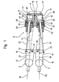
- 1 to 9 with 1 is a cable feeder referred to, which essentially consists of a first Drive unit 2, from a second drive unit 3 with grippers 4.5.
- the first drive unit 2 has For example, a rotatable about a third pivot point 6 Platform 7 which, for example, has a belt 8 is driven by a motor 9.
- the second Drive unit 3 is carried by platform 7 and on this in the direction of an axis 10 by means of a third Drive unit 2.1 slidably arranged.
- the second drive unit 3 consists of one of the Platform 7 worn console 11 with cylinders 12, 13 and a third boom 14 of the console 11, the third Boom 14, the grippers 4,5 are rotatably mounted.
- the linear movement shown in Fig. 4 is the total second drive unit 3 including the grippers 4, 5 moved by means of the third drive unit.
- the first Gripper 4 is on a first boom 15 with two Legs 16, 17 or the second gripper 5 is on one second boom 18 with two legs 19,20 arranged.
- the second leg 17 of the first boom 15 is on one first pivot point 21 of the third boom 14 or the fourth leg 20 of the second boom 18 is on one second pivot point 22 of the third boom 14 is mounted.
- the first gripper 4 is For example, designed as a centering gripper and holds a first cable end 25 or the second gripper 5 is designed for example as a centering gripper and holds a second cable end 26.
- the cable ends 25.26 can be the ends of a cable or one end of a cable his.
- 27 is a first cable axis or with 28 is one denotes the second cable axis, the cable axes 27, 28 depending on the position of the piston rods 23, 24 in parallel, by the third pivot 6 or very much from the parallel position can run differently.
- first piston 29 and second piston 30 or in the second cylinder 13 are one third piston 31 and a fourth piston 32 are arranged, by means of which the different mentioned above Positions of the first piston rod 23 and the second Piston rod 24 are feasible.
- the first cylinder 12 forms with the pistons 29, 30 a first chamber 33, a second Chamber 34 and a third chamber 35 and the second Cylinder 13 forms a fourth chamber with pistons 31, 32 36, a fifth chamber 37 and a sixth chamber 38, wherein the first chamber 33 a first pressure medium inlet 39, the second chamber 34 a second pressure medium inlet 40, the third chamber 35 a third pressure medium inlet 41 or the fourth chamber 36 has a fourth pressure medium inlet 42, the fifth chamber 37 has a fifth pressure medium inlet 43 and the sixth chamber 38 has a sixth pressure medium inlet 44 has.
- the pistons 29,30 are pressed against each other and in connection with the second piston 30 standing first piston rod 23 the first Gripper 4 so that the first cable axis 27 through the third pivot 6 runs.
- the Seal sleeve mounted or a contact with crimp technology connected to the cable end 25,26.
- the sixth pressure medium inlet 44 is acted upon, wherein the pistons 31, 32 are pressed in the direction of the second gripper 5 and in connection with the fourth piston 32 standing second piston rod 24 the second gripper 5 so represents that the second cable axis 28 the parallel position occupies.
- the cable ends are 25, 26 stripped simultaneously, as shown in Figs. 3 and 6 the first cable axis also has 27 parallel positions.
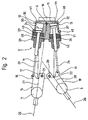
- Fig. 4 shows the cable feeder 1 in the pivoted position, the second drive unit 3 on the platform 7 in the Direction of the axis 10 away from the stripping machine 45 by means of third drive unit has been moved. With The broken line is the position of the grippers in the Working area of the assembly units shown.
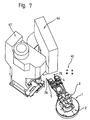
- Fig. 7 shows the cable feeder 1 with the first cable end 25 in the processing area of a machine 46 for assembly of sealing grommets, both cable axes 27.28 through the third pivot point 6.
- the grippers 4,5 shown in FIGS. 6, 7, 8 serve the Feeding the leading cable ends 25.26, in Technical jargon called page 1 to the assembly units 45,46,47.
- the cable ends 25,26 are not by means of a shown feed unit from the rear through the Gripper 4.5 advanced.
- the grippers 4.5 point On the machining side, as shown in FIG. 6, guide tubes 4.1.5.1 through which the cable ends 25.26 are pushed through and which of the guide of the cable ends 24.26 serve.
- the structure of the grippers 4, 5 of page 1 is such that they only hold the cable ends 25, 26 can. After assembling page 1, the Gripper 4.5 back to the stripping machine 45.
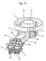
- a feeder 1 as in Fig. 9 shown adopted.
- the feeder according to FIG. 9 is equipped with grippers 4,5, which grip the cable ends, hold on or let go. To do this Functions are necessary gripper jaws 4.2.5.2 can open and close.
- Fig. 9 shows one Gripper 4 with closed, interlocking Gripper jaws 4.2 and the other gripper 5 with open Gripper jaws 5.2.
- the second Drive unit 3 below and the third drive unit 2.1 arranged above the platform 7.
- With 7.1 is a Designated flange on which the third drive unit 2.1 for the linear displacement of the second shown in FIG. 4 Drive unit 3 is arranged. For example, intervenes not shown pinion in a not shown Rack and generates the linear displacement of the second drive unit 3.
- the positions of the grippers 4, 5 are not those in the Figures shown positions limited. Each gripper 4,5 can the parallel position, the position with the cable axis 27.28 through the third pivot 6 or the location outside occupy a machining area.
- the grippers 4,5 also horizontally, for example downwards from the respective work area.
- the Processing machines instead of the ones shown above Circular arrangement can be arranged on a straight line
- the second drive unit 3 instead of the rotational movement performs a linear movement.
- the first drive unit 2 with for example a linear actuator moves in in this case on a linear axis.
- the position of the grippers 4.5, where the cable axis 23.24 through the third Pivot 6 runs, can with the linear feed omitted.
- the cable end 25.26 with one of horizontal, vertical, linear and / or rotary components existing movement Assembly units are brought.
Landscapes
- Engineering & Computer Science (AREA)
- Manufacturing & Machinery (AREA)
- Manufacturing Of Electrical Connectors (AREA)
Claims (5)
- Dispositif pour amener des extrémités de câbles dans des unités de confection qui les traitent, caractérisé en ce qu'il est prévu un dispositif d'amenée (1) avec deux organes de préhension (4, 5) qui amènent des extrémités de câble respectives (25, 26) en vue du traitement.
- Dispositif selon la revendication 1, caractérisé en ce que le dispositif d'amenée (1) comporte des unités d'entraínement (2, 2.1, 3) pour le mouvement d'amenée des organes de préhension (4, 5).
- Dispositif selon la revendication 1 ou 2, caractérisé en ce que le dispositif d'amenée (1) comporte des unités d'entraínement (2, 2.1) communes aux organes de préhension (4, 5) pour les mouvements linéaires et/ou rotatifs de ceux-ci.
- Dispositif selon la revendication 3, caractérisé en ce que les organes de préhension (4, 5) sont aptes à être déplacés jusqu'à des positions pour l'amenée des extrémités de câbles (25, 26) ou des positions pour le traitement de celles-ci.
- Dispositif selon l'une des revendications précédentes, caractérisé en ce qu'il est prévu, pour déplacer les organes de préhension (4, 5), des entraínements (12, 13, 23, 24, 29, 30) qui actionnent des bras (15, 18) sur lesquels sont disposés les organes de préhension (4, 5), les bras (15, 18) et les entraínements (12, 13, 23, 24, 29, 30) étant disposés sur une console (11) mobile grâce aux unités d'entraínement communes (2, 2.1) et pourvue d'un bras (14).
Priority Applications (1)
| Application Number | Priority Date | Filing Date | Title |
|---|---|---|---|
| EP20000102369 EP1028501B1 (fr) | 1999-02-12 | 2000-02-04 | Dispositif de transport d'extrémités de câble pour une unité de confection de câbles |
Applications Claiming Priority (3)
| Application Number | Priority Date | Filing Date | Title |
|---|---|---|---|
| EP99810132 | 1999-02-12 | ||
| EP99810132 | 1999-02-12 | ||
| EP20000102369 EP1028501B1 (fr) | 1999-02-12 | 2000-02-04 | Dispositif de transport d'extrémités de câble pour une unité de confection de câbles |
Publications (2)
| Publication Number | Publication Date |
|---|---|
| EP1028501A1 EP1028501A1 (fr) | 2000-08-16 |
| EP1028501B1 true EP1028501B1 (fr) | 2003-04-23 |
Family
ID=26070502
Family Applications (1)
| Application Number | Title | Priority Date | Filing Date |
|---|---|---|---|
| EP20000102369 Expired - Lifetime EP1028501B1 (fr) | 1999-02-12 | 2000-02-04 | Dispositif de transport d'extrémités de câble pour une unité de confection de câbles |
Country Status (1)
| Country | Link |
|---|---|
| EP (1) | EP1028501B1 (fr) |
Families Citing this family (2)
| Publication number | Priority date | Publication date | Assignee | Title |
|---|---|---|---|---|
| CN108604785B (zh) | 2016-01-26 | 2020-08-21 | 科迈士瑞士股份有限公司 | 线缆加工装置 |
| DE102018212462B4 (de) * | 2018-07-26 | 2020-03-26 | Leoni Bordnetz-Systeme Gmbh | Anlage sowie Verfahren zur automatischen Konfektionierung von Leitungen |
Family Cites Families (3)
| Publication number | Priority date | Publication date | Assignee | Title |
|---|---|---|---|---|
| CH673858A5 (en) * | 1986-12-03 | 1990-04-12 | Megomat Ag | Cable sections make-up set - consisting of two grippers, two auxiliary grippers, and cutting stripping unit for cable press |
| EP0303724A1 (fr) * | 1987-08-19 | 1989-02-22 | Hans Hackner | Appareil pour couper et dénuder des fils et pour sertir des connexions serties, à fiche et à vis ainsi que pour réaliser des structures en chaîne |
| CH692778A5 (de) * | 1997-05-07 | 2002-10-31 | Komax Holding Ag | Greifer. |
-
2000
- 2000-02-04 EP EP20000102369 patent/EP1028501B1/fr not_active Expired - Lifetime
Also Published As
| Publication number | Publication date |
|---|---|
| EP1028501A1 (fr) | 2000-08-16 |
Similar Documents
| Publication | Publication Date | Title |
|---|---|---|
| DE68910186T2 (de) | Arbeitsform für eine Jacke. | |
| EP1313575B1 (fr) | Systeme de transport a bras articule | |
| DE3429231A1 (de) | Wendevorrichtung | |
| DE69207319T2 (de) | Vorrichtung und Maschine zum Einfügen von Verbindungselementen in Verbindern | |
| EP0598276B1 (fr) | Dispositif d'amenée et de changement de câble pour machine de traitement de câble | |
| DE2702104A1 (de) | Verfahren und vorrichtung zur automatischen auswechslung eines werkstuecks an einer werkzeugmaschine | |
| EP3336976B1 (fr) | Dispositif de traitement de câble | |
| DE3141786A1 (de) | Vorrichtung zum verbinden der wicklungsenden mit den anschlussklemmen von statoren elektrischer maschinen und ein verfahren zum betrieb derselben | |
| DE1479547C3 (de) | Vorrichtung zum gleichzeitigen Entfernen überflüssiger Abfallabschnitte von mehreren fertig geformten Kunststoffteilen, insbesondere von nach dem Blasverfahren hergestellten Hohlkörpern | |
| DE9414501U1 (de) | Bearbeitungsmaschine mit relativverschiebbaren Drehvorrichtungen | |
| DE102010017981B4 (de) | Einrichtung und Verfahren zum Zusammenführen von Leitern | |
| DE3909093A1 (de) | Verfahren und vorrichtung zum bearbeiten von kabelmaterial | |
| EP1366834B1 (fr) | Dispositif de changement d'outil pour presses | |
| EP1028501B1 (fr) | Dispositif de transport d'extrémités de câble pour une unité de confection de câbles | |
| EP0584493B1 (fr) | Dispositif à faire un paquet pour machines de traitement de câbles | |
| DE3315227C2 (de) | Crimpverfahren sowie Crimpvorrichtung zur Durchführung des Verfahrens | |
| DE3125394A1 (de) | Schmiedemaschinen-foerderer | |
| AT411033B (de) | Bearbeitungsstation | |
| DE3140797A1 (de) | Vorrichtung zum automatischen zufuehren und entnehmen von werkstuecken fuer rundlauf-fraesmaschinen | |
| DE3718886C2 (fr) | ||
| EP0020850A1 (fr) | Dispositif de maintien de l'ouvrage | |
| DE3005667C2 (fr) | ||
| EP1983621B1 (fr) | Dispositif de traitement de câble | |
| EP0411392B1 (fr) | Procédé pour l'insertion mécanique dans des chambres de boîtiers | |
| DE19547510C2 (de) | Verfahren und Vorrichtung zum Bandagieren von Statoren |
Legal Events
| Date | Code | Title | Description |
|---|---|---|---|
| PUAI | Public reference made under article 153(3) epc to a published international application that has entered the european phase |
Free format text: ORIGINAL CODE: 0009012 |
|
| AK | Designated contracting states |
Kind code of ref document: A1 Designated state(s): CH DE FR GB IT LI |
|
| AX | Request for extension of the european patent |
Free format text: AL;LT;LV;MK;RO;SI |
|
| 17P | Request for examination filed |
Effective date: 20010117 |
|
| AKX | Designation fees paid |
Free format text: CH DE FR GB IT LI |
|
| 17Q | First examination report despatched |
Effective date: 20011107 |
|
| GRAG | Despatch of communication of intention to grant |
Free format text: ORIGINAL CODE: EPIDOS AGRA |
|
| GRAG | Despatch of communication of intention to grant |
Free format text: ORIGINAL CODE: EPIDOS AGRA |
|
| GRAH | Despatch of communication of intention to grant a patent |
Free format text: ORIGINAL CODE: EPIDOS IGRA |
|
| GRAH | Despatch of communication of intention to grant a patent |
Free format text: ORIGINAL CODE: EPIDOS IGRA |
|
| GRAA | (expected) grant |
Free format text: ORIGINAL CODE: 0009210 |
|
| AK | Designated contracting states |
Designated state(s): CH DE FR GB IT LI |
|
| REG | Reference to a national code |
Ref country code: GB Ref legal event code: FG4D Free format text: NOT ENGLISH |
|
| REG | Reference to a national code |
Ref country code: CH Ref legal event code: EP |
|
| REF | Corresponds to: |
Ref document number: 50001827 Country of ref document: DE Date of ref document: 20030528 Kind code of ref document: P |
|
| REG | Reference to a national code |
Ref country code: CH Ref legal event code: NV Representative=s name: ING. HANS LUDESCHER, PATENTABTEILUNG DER SFS GRUPP |
|
| GBT | Gb: translation of ep patent filed (gb section 77(6)(a)/1977) | ||
| ET | Fr: translation filed | ||
| PLBE | No opposition filed within time limit |
Free format text: ORIGINAL CODE: 0009261 |
|
| STAA | Information on the status of an ep patent application or granted ep patent |
Free format text: STATUS: NO OPPOSITION FILED WITHIN TIME LIMIT |
|
| 26N | No opposition filed |
Effective date: 20040126 |
|
| PGFP | Annual fee paid to national office [announced via postgrant information from national office to epo] |
Ref country code: GB Payment date: 20090219 Year of fee payment: 10 |
|
| GBPC | Gb: european patent ceased through non-payment of renewal fee |
Effective date: 20100204 |
|
| PG25 | Lapsed in a contracting state [announced via postgrant information from national office to epo] |
Ref country code: GB Free format text: LAPSE BECAUSE OF NON-PAYMENT OF DUE FEES Effective date: 20100204 |
|
| PGFP | Annual fee paid to national office [announced via postgrant information from national office to epo] |
Ref country code: FR Payment date: 20140219 Year of fee payment: 15 |
|
| REG | Reference to a national code |
Ref country code: FR Ref legal event code: ST Effective date: 20151030 |
|
| PG25 | Lapsed in a contracting state [announced via postgrant information from national office to epo] |
Ref country code: FR Free format text: LAPSE BECAUSE OF NON-PAYMENT OF DUE FEES Effective date: 20150302 |
|
| PGFP | Annual fee paid to national office [announced via postgrant information from national office to epo] |
Ref country code: IT Payment date: 20190225 Year of fee payment: 20 Ref country code: CH Payment date: 20190218 Year of fee payment: 20 Ref country code: DE Payment date: 20190219 Year of fee payment: 20 |
|
| REG | Reference to a national code |
Ref country code: DE Ref legal event code: R071 Ref document number: 50001827 Country of ref document: DE |
|
| REG | Reference to a national code |
Ref country code: CH Ref legal event code: PL |