EP1028513A2 - Support de pôles saillantes - Google Patents
Support de pôles saillantes Download PDFInfo
- Publication number
- EP1028513A2 EP1028513A2 EP00102552A EP00102552A EP1028513A2 EP 1028513 A2 EP1028513 A2 EP 1028513A2 EP 00102552 A EP00102552 A EP 00102552A EP 00102552 A EP00102552 A EP 00102552A EP 1028513 A2 EP1028513 A2 EP 1028513A2
- Authority
- EP
- European Patent Office
- Prior art keywords
- pole
- insulating body
- machine according
- windings
- stator
- Prior art date
- Legal status (The legal status is an assumption and is not a legal conclusion. Google has not performed a legal analysis and makes no representation as to the accuracy of the status listed.)
- Granted
Links
- 238000004804 winding Methods 0.000 claims abstract description 46
- 238000004519 manufacturing process Methods 0.000 claims abstract description 13
- 238000000034 method Methods 0.000 claims description 10
- 238000009413 insulation Methods 0.000 claims description 7
- 238000006073 displacement reaction Methods 0.000 claims description 5
- 238000012856 packing Methods 0.000 claims description 5
- 230000008569 process Effects 0.000 claims description 4
- 230000008901 benefit Effects 0.000 description 4
- 239000012212 insulator Substances 0.000 description 4
- 238000004806 packaging method and process Methods 0.000 description 3
- 230000004907 flux Effects 0.000 description 2
- 238000010438 heat treatment Methods 0.000 description 2
- 238000005299 abrasion Methods 0.000 description 1
- 238000001816 cooling Methods 0.000 description 1
- 238000006056 electrooxidation reaction Methods 0.000 description 1
- 230000017525 heat dissipation Effects 0.000 description 1
- 238000002347 injection Methods 0.000 description 1
- 239000007924 injection Substances 0.000 description 1
- 238000009434 installation Methods 0.000 description 1
- 235000015095 lager Nutrition 0.000 description 1
- 239000000463 material Substances 0.000 description 1
- 239000002184 metal Substances 0.000 description 1
- 238000003825 pressing Methods 0.000 description 1
- 238000004080 punching Methods 0.000 description 1
- 230000009467 reduction Effects 0.000 description 1
- 238000000926 separation method Methods 0.000 description 1
- 238000003860 storage Methods 0.000 description 1
Images

Classifications
-
- H—ELECTRICITY
- H02—GENERATION; CONVERSION OR DISTRIBUTION OF ELECTRIC POWER
- H02K—DYNAMO-ELECTRIC MACHINES
- H02K5/00—Casings; Enclosures; Supports
- H02K5/04—Casings or enclosures characterised by the shape, form or construction thereof
- H02K5/16—Means for supporting bearings, e.g. insulating supports or means for fitting bearings in the bearing-shields
- H02K5/161—Means for supporting bearings, e.g. insulating supports or means for fitting bearings in the bearing-shields radially supporting the rotary shaft at both ends of the rotor
-
- H—ELECTRICITY
- H02—GENERATION; CONVERSION OR DISTRIBUTION OF ELECTRIC POWER
- H02K—DYNAMO-ELECTRIC MACHINES
- H02K1/00—Details of the magnetic circuit
- H02K1/06—Details of the magnetic circuit characterised by the shape, form or construction
- H02K1/12—Stationary parts of the magnetic circuit
- H02K1/14—Stator cores with salient poles
- H02K1/146—Stator cores with salient poles consisting of a generally annular yoke with salient poles
- H02K1/148—Sectional cores
-
- H—ELECTRICITY
- H02—GENERATION; CONVERSION OR DISTRIBUTION OF ELECTRIC POWER
- H02K—DYNAMO-ELECTRIC MACHINES
- H02K3/00—Details of windings
- H02K3/46—Fastening of windings on the stator or rotor structure
- H02K3/52—Fastening salient pole windings or connections thereto
- H02K3/521—Fastening salient pole windings or connections thereto applicable to stators only
- H02K3/524—Fastening salient pole windings or connections thereto applicable to stators only for U-shaped, E-shaped or similarly shaped cores
-
- H—ELECTRICITY
- H02—GENERATION; CONVERSION OR DISTRIBUTION OF ELECTRIC POWER
- H02K—DYNAMO-ELECTRIC MACHINES
- H02K5/00—Casings; Enclosures; Supports
- H02K5/04—Casings or enclosures characterised by the shape, form or construction thereof
- H02K5/12—Casings or enclosures characterised by the shape, form or construction thereof specially adapted for operating in liquid or gas
- H02K5/128—Casings or enclosures characterised by the shape, form or construction thereof specially adapted for operating in liquid or gas using air-gap sleeves or air-gap discs
Definitions
- the invention relates to an electric motor, in particular for Operation of a pump, with a stator by windings has surrounding pole pieces, and with a pole ring, the Surrounds pole piece and to which the pole piece can be detached are attached.
- the invention also relates to Method for producing the stator package of such a Electric motor.
- Electric motors which have a pole ring have molded pole legs, the pole ring in a number of segments corresponding to the number of pole legs can be divided. Since the pole ring and pole leg are one must form such from pole ring and pole legs existing stator packages with so-called needle winders be wound. Doing so will needles from one face of the stator package between the pole legs and thereby the wire is placed around a polar arm.
- This way of wrapping has the disadvantage that the turns of the wire within the Winding have a large number of crossing points what to a correspondingly reduced packing density and thus to increase the winding length (average coil length) leads. At the same time, the correspondingly greater length of the Winding wire the manufacturing cost of the motor what just is particularly important for small engines.
- the object of the present invention is therefore a electrical machine, in particular an electric motor create, the stator package with small size and high efficiency simple and inexpensive by machine can be made.
- it is an object of the invention Method for producing a stator package of the To create motor according to the invention.
- the essence of the invention is that all pole legs of one common insulating body designed as a pole piece support are kept in the after mounting the pole piece in Stator package and thus in the electrical machine especially the electric motor remains.
- This insulating body offers great advantages in the manufacture of motors, than now the individual pole pieces of Coil winders, especially those specially designed for a layer Winding suitable flyer winders, can be wound, before the package of pole pieces held by the insulator is inserted as a whole into the pole ring.
- the wrapping by flyer winder is in contrast to the known Needle winders are particularly advantageous because the windings can be applied in layers and without crossings, so that a compact winding with low application results. Moreover it is possible to wrap with large wire cross sections, so that the windings can be designed for high currents.
- the insulating body according to the invention is advantageously as a completely surrounding and in particular from the rotor Plastic molded sleeve formed in its wall Recesses for inserting or inserting the individual Has pole piece.
- the pole pieces are in kept in the correct position, being wound Base, the winding sections, the pole leg radially from protrude from the outer surface of the jacket.
- Storage in the sleeve-shaped insulating body ensures one hand good access for the winding machine to the winding sections and on the other hand aligns the pole legs in the right one Location for later installation.
- Introducing the Pole leg in the insulating body is particularly simple, if this consists of two axially joinable half shells is constructed. Then the pole legs can be inserted in one Half shell are used before the other half shell final mounting of the pole piece is placed.
- Insulating bodies are on the outside facing away from the rotor frame-shaped brackets surrounding the pole legs intended. These brackets are designed to be the Border the winding sections of the pole legs and templates form on which the stator windings can be wound.
- the insulating body with the holders is advantageously molded in one piece from plastic. On the one hand, this is the ensures cost-effective production of the insulating body, while on the other hand those with rounded corners and edges provided plastic components the winding wires one provide good protection against abrasion of the insulation.
- the insulating body additional functions.
- Front receiving parts are provided in the insulation displacement contacts for contacting the stator windings can be used.
- the receiving parts can be injection molded or be attachable.
- the plug contacts created in this way ensure a fully automatic assembly of all Components in the axial direction.
- the insulating body other components to optimize the leadership and Have contacting of the winding ends.
- the insulating body can also include means for receiving a bearing for the shaft exhibit. It can also be pushed onto a can or even as a can for a can motor be trained. In this form, one can be on one end Bearing plate and on the other face a receptacle for a plain bearing may be provided.
- the advantage of one comes from the high packing density smaller size of the motors with lower manufacturing and Material costs and higher efficiency because of the lower required wire length.
- the increased packing density is reduced likewise the risk of noise in the Winding.
- the high packing density Amount of trapped air and therefore the danger electrochemical corrosion reduced. That goes along with it higher insulation strength and better Heat dissipation.
- Multi-phase systems such as three-phase machines each have pairs of opposite windings with a continuous wire can be wound so that on a contact connection between the two windings of a pair can.
- the pole ring and the pole legs are made using the technique of the so-called Stamping packaging ".
- the stamping makes it possible to produce pole legs of any cross-section with high precision. After the sheets have been joined together to form a sheet-metal component, the accuracy of the sheets is transferred to the contour of the component.
- a particular advantage of the process is that now closed pole rings are also used The closed pole rings have no gaps that hinder the magnetic flux, so that vibrations are excluded.
- stator packs pole rings and Pole legs are made with very precise Linear guides are allowed.
- the tolerances of the Guides can be dimensioned so that the Pole legs are permanently pressed into the pole ring can, the air gap between the pole ring and the foot of a pole leg a width of a few micrometers having. This air gap is in relation to the air gap between the rotor and the stator too small to be the could affect magnetic flux to the pole ring.
- the stators according to the invention in all electrical Machines can be used, it is particularly advantageous the stator packages according to the invention in fan motors or at Provide canned motors, which in particular Centrifugal pumps can be used for heating or cooling systems.
- a dovetail guide is special advantageous because it has a positive hold in radial and offers in the circumferential direction and far through the Process of punching packaging simply with such tolerances can be made so that the sled part well on or pressed into the bed of the guide. This is the type comparatively insensitive to leadership Manufacturing tolerances.
- the pole legs are in the pole ring by means of an axially arranged Linear guide, especially a dovetail guide, insertable, it being particularly advantageous that Train linear guide so that the pole legs as in Insulated package bundled in the guide grooves can be pressed in. Since the pressing is completely automated can happen is a simple and inexpensive Manufacturing guaranteed.
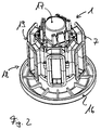
- FIG. 1 shows an insulating body 1 molded from plastic shown.
- the insulating body is cylindrical in the form of a not shown rotor surrounding an electrical machine
- the sleeve designs and has recesses 2 in its wall for the use shown in Figure 3 pole piece 3.
- the insulating body is 1st constructed in two parts from two halves (half shells) 4 and 5, which are assembled in the axial direction at the joint 6 are.
- On the outer jacket of the insulating body 1 are frame-shaped Brackets 7 formed, which surround the recesses 2.
- the brackets 7 are provided with collars 8, which are axial Limitation of the stator windings, not shown, on the holder are wound up.
- the cross section of the brackets 7, in particular the angle of the molded Collar 8, is designed so that the stator windings layered winding are supported.
- Both windings are thus through the connecting wire section 10 to the pair coupled.
- the wire section 10 is on the front side of the Insulating body 1 guided in guides 12 or around pin 13.
- the insulating body according to Figure 1 has in its end face a bore 22 which is suitable for receiving a bearing is.
- the remaining six wire ends 11 are in recordings 14 introduced on the front of the insulating body are arranged and in which insulation displacement contacts 15 are used.
- the insulation displacement contacts 15 serve on the one hand for fixing the wire ends 11 and on the other hand for external contact.
- the insulating body 1 shown in Figure 2 forms the complete Can of a can engine, for example one Heating pump that has a hydraulic separation between the Stator and the rotor manufactures.
- Components described has the insulating body 1 on its an end face a molded bearing plate 16 and its other end face a receptacle 17 for a plain bearing on.
- the insulating body is 1 in two parts.
- One part 18 is with the can molded bearing debt 16 and 17 formed
- the other part 19 is a ring that holds the remaining halves the frame 7 carries and which can be pushed onto the part 19.
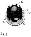
- FIG. 3 the insulating body according to Figure 2 is with inserted pole legs 3 shown. Clearly visible are the poles of the pole legs 3 opposite Foot areas that are provided with a dovetail 21. After the pole limbs 3 have been wound, this is shown in FIG shown package in a pole ring, not shown corresponding guides pressed.
- the process for producing a stator package for a electrical machine runs with the following steps. First, the pole pieces 3 are inserted into the recesses 2 of the insulating body 1, in particular a part of the Insulating body 1 used. Then the second part of the Insulator 1 placed and the pole piece directly or the holders 7 wrapped with flyer windings. Last will this package is pressed into the pole ring.
Landscapes
- Engineering & Computer Science (AREA)
- Power Engineering (AREA)
- Manufacture Of Motors, Generators (AREA)
- Insulation, Fastening Of Motor, Generator Windings (AREA)
- Motor Or Generator Frames (AREA)
- Iron Core Of Rotating Electric Machines (AREA)
Applications Claiming Priority (2)
| Application Number | Priority Date | Filing Date | Title |
|---|---|---|---|
| DE1999105948 DE19905948A1 (de) | 1999-02-12 | 1999-02-12 | Polschenkelträger |
| DE19905948 | 1999-02-12 |
Publications (3)
| Publication Number | Publication Date |
|---|---|
| EP1028513A2 true EP1028513A2 (fr) | 2000-08-16 |
| EP1028513A3 EP1028513A3 (fr) | 2000-12-20 |
| EP1028513B1 EP1028513B1 (fr) | 2008-05-28 |
Family
ID=7897340
Family Applications (1)
| Application Number | Title | Priority Date | Filing Date |
|---|---|---|---|
| EP20000102552 Expired - Lifetime EP1028513B1 (fr) | 1999-02-12 | 2000-02-07 | Support de pôles saillantes |
Country Status (2)
| Country | Link |
|---|---|
| EP (1) | EP1028513B1 (fr) |
| DE (2) | DE19905948A1 (fr) |
Cited By (3)
| Publication number | Priority date | Publication date | Assignee | Title |
|---|---|---|---|---|
| EP1499000A1 (fr) * | 2003-07-12 | 2005-01-19 | Grundfos a/s | Stator segmenté |
| EP1347556A3 (fr) * | 2002-03-21 | 2005-11-30 | Robert Bosch Gmbh | Stator de machine électrique tournante |
| WO2009127525A1 (fr) * | 2008-04-18 | 2009-10-22 | Continental Automotive Gmbh | Support isolant pour un stator d’un moteur électrique destiné à entraîner des pompes hydrauliques |
Families Citing this family (1)
| Publication number | Priority date | Publication date | Assignee | Title |
|---|---|---|---|---|
| DE202014005789U1 (de) | 2014-07-17 | 2015-10-23 | Brose Fahrzeugteile Gmbh & Co. Kommanditgesellschaft, Coburg | Stator eines Elektromotors sowie Kontaktsystem hierfür |
Family Cites Families (7)
| Publication number | Priority date | Publication date | Assignee | Title |
|---|---|---|---|---|
| DE3172692D1 (en) * | 1981-05-06 | 1985-11-28 | Amp Inc | Electric motor stator and a method of manufacturing the stator |
| GB2172444B (en) * | 1985-03-09 | 1988-08-17 | Asmo Co Ltd | Stator for an electric motor |
| DE3843477A1 (de) * | 1988-12-23 | 1990-06-28 | Oplaender Wilo Werk Gmbh | Spaltrohr-elektromotor |
| JPH0775270A (ja) * | 1993-09-03 | 1995-03-17 | Canon Electron Inc | 電磁回転機用の回転磁界発生ユニット |
| DE19740938A1 (de) * | 1997-09-17 | 1999-03-18 | Trw Fahrzeugelektrik | Stator für einen Elektromotor, insbesondere bürstenlosen Gleichstrommotor |
| DE19740937A1 (de) * | 1997-09-17 | 1999-03-18 | Trw Fahrzeugelektrik | Stator und Verfahren zum Bewickeln eines Stators für einen bürstenlosen Gleichstrommotor |
| IT1296730B1 (it) * | 1997-10-16 | 1999-07-15 | Bitron Spa | Statore per motori elettrici con rivestimento costampato elettricamente isolante. |
-
1999
- 1999-02-12 DE DE1999105948 patent/DE19905948A1/de not_active Withdrawn
-
2000
- 2000-02-07 DE DE50015176T patent/DE50015176D1/de not_active Expired - Lifetime
- 2000-02-07 EP EP20000102552 patent/EP1028513B1/fr not_active Expired - Lifetime
Cited By (3)
| Publication number | Priority date | Publication date | Assignee | Title |
|---|---|---|---|---|
| EP1347556A3 (fr) * | 2002-03-21 | 2005-11-30 | Robert Bosch Gmbh | Stator de machine électrique tournante |
| EP1499000A1 (fr) * | 2003-07-12 | 2005-01-19 | Grundfos a/s | Stator segmenté |
| WO2009127525A1 (fr) * | 2008-04-18 | 2009-10-22 | Continental Automotive Gmbh | Support isolant pour un stator d’un moteur électrique destiné à entraîner des pompes hydrauliques |
Also Published As
| Publication number | Publication date |
|---|---|
| DE19905948A1 (de) | 2000-08-17 |
| DE50015176D1 (de) | 2008-07-10 |
| EP1028513B1 (fr) | 2008-05-28 |
| EP1028513A3 (fr) | 2000-12-20 |
Similar Documents
| Publication | Publication Date | Title |
|---|---|---|
| DE112008002806B4 (de) | Drehende elektrische Maschine | |
| DE2244806C2 (de) | Dynamoelektrische Maschine | |
| DE19643561C1 (de) | Elektrische Maschine mit einer Einzelpolwicklung | |
| DE69504318T2 (de) | Elektrische maschinen und ihre komponenten die folienwellenlager enthalten | |
| DE102016224526A1 (de) | Stator einer elektrischen Maschine, elektrische Maschine sowie Verlege- und Kontakteinrichtung für eine elektrische Maschine | |
| DE112004001908T5 (de) | Anker einer sich drehenden elektrischen Maschine und deren Herstellverfahren | |
| DE112011100325T5 (de) | Sammelschieneneinheit und Motor | |
| DE102010064051A1 (de) | Wicklungsträger zur Isolation einer Einzelzahnwicklung bei elektrischen Maschinen | |
| DE112005000816T5 (de) | Bürstenloser Motor | |
| WO2007137656A1 (fr) | Procédé de fabrication d'un stator et stator correspondant | |
| WO2018192817A1 (fr) | Module de dent polaire pour une machine électrique, pièce active pourvue d'un module de dent polaire et machine électrique | |
| EP1014536A2 (fr) | Empilage statorique avec des poles en saillie insérables | |
| DE112008002752T5 (de) | Stator und rotierende elektrische Maschine | |
| DE112018001742T5 (de) | Motor | |
| DE202014005789U1 (de) | Stator eines Elektromotors sowie Kontaktsystem hierfür | |
| EP3352341B1 (fr) | Stator et procédé de fabrication d'un stator | |
| DE19503610C2 (de) | Mehrphasige und vielpolige, elektrisch kommutierbare Maschine und Verfahren zur Herstellung des Ständers | |
| DE112013001643T5 (de) | Elektrische rotierende Maschine | |
| EP3488516B1 (fr) | Stator d'un machine à courant alternatif | |
| DE112016005116T5 (de) | Wicklungs- und statoranordnung einer elektrorotationsmaschine | |
| EP1024581B1 (fr) | Connexions des enroulements d'un moteur | |
| EP1041697B1 (fr) | Machine à réluctance avec au moins deux pôles saillants, chacun avec bobinage d'excitation et procédé de fabrication du stator d'une telle machine | |
| EP1028513B1 (fr) | Support de pôles saillantes | |
| WO2023143905A1 (fr) | Rotor comprenant un siège de palier en deux parties | |
| WO2019215031A1 (fr) | Stator d'une machine électrique, machine électrique et équipement de connexion |
Legal Events
| Date | Code | Title | Description |
|---|---|---|---|
| PUAI | Public reference made under article 153(3) epc to a published international application that has entered the european phase |
Free format text: ORIGINAL CODE: 0009012 |
|
| AK | Designated contracting states |
Kind code of ref document: A2 Designated state(s): DE FR GB IT |
|
| AX | Request for extension of the european patent |
Free format text: AL;LT;LV;MK;RO;SI |
|
| PUAL | Search report despatched |
Free format text: ORIGINAL CODE: 0009013 |
|
| AK | Designated contracting states |
Kind code of ref document: A3 Designated state(s): AT BE CH CY DE DK ES FI FR GB GR IE IT LI LU MC NL PT SE |
|
| AX | Request for extension of the european patent |
Free format text: AL;LT;LV;MK;RO;SI |
|
| 17P | Request for examination filed |
Effective date: 20010620 |
|
| AKX | Designation fees paid |
Free format text: DE FR GB IT |
|
| RAP1 | Party data changed (applicant data changed or rights of an application transferred) |
Owner name: WILO AG |
|
| GRAP | Despatch of communication of intention to grant a patent |
Free format text: ORIGINAL CODE: EPIDOSNIGR1 |
|
| RIN1 | Information on inventor provided before grant (corrected) |
Inventor name: SCHRECKENBERG, STEPHAN Inventor name: GENSTER, ALBERT Inventor name: KECH, HANSJUERGEN Inventor name: LUETKENHAUS, NORBERT |
|
| GRAS | Grant fee paid |
Free format text: ORIGINAL CODE: EPIDOSNIGR3 |
|
| GRAA | (expected) grant |
Free format text: ORIGINAL CODE: 0009210 |
|
| AK | Designated contracting states |
Kind code of ref document: B1 Designated state(s): DE FR GB IT |
|
| REG | Reference to a national code |
Ref country code: GB Ref legal event code: FG4D Free format text: NOT ENGLISH |
|
| REF | Corresponds to: |
Ref document number: 50015176 Country of ref document: DE Date of ref document: 20080710 Kind code of ref document: P |
|
| PLBE | No opposition filed within time limit |
Free format text: ORIGINAL CODE: 0009261 |
|
| STAA | Information on the status of an ep patent application or granted ep patent |
Free format text: STATUS: NO OPPOSITION FILED WITHIN TIME LIMIT |
|
| 26N | No opposition filed |
Effective date: 20090303 |
|
| REG | Reference to a national code |
Ref country code: FR Ref legal event code: PLFP Year of fee payment: 16 |
|
| PGFP | Annual fee paid to national office [announced via postgrant information from national office to epo] |
Ref country code: DE Payment date: 20150203 Year of fee payment: 16 Ref country code: IT Payment date: 20150213 Year of fee payment: 16 |
|
| PGFP | Annual fee paid to national office [announced via postgrant information from national office to epo] |
Ref country code: FR Payment date: 20150210 Year of fee payment: 16 Ref country code: GB Payment date: 20150204 Year of fee payment: 16 |
|
| REG | Reference to a national code |
Ref country code: DE Ref legal event code: R119 Ref document number: 50015176 Country of ref document: DE |
|
| GBPC | Gb: european patent ceased through non-payment of renewal fee |
Effective date: 20160207 |
|
| REG | Reference to a national code |
Ref country code: FR Ref legal event code: ST Effective date: 20161028 |
|
| PG25 | Lapsed in a contracting state [announced via postgrant information from national office to epo] |
Ref country code: IT Free format text: LAPSE BECAUSE OF NON-PAYMENT OF DUE FEES Effective date: 20160207 |
|
| PG25 | Lapsed in a contracting state [announced via postgrant information from national office to epo] |
Ref country code: GB Free format text: LAPSE BECAUSE OF NON-PAYMENT OF DUE FEES Effective date: 20160207 Ref country code: FR Free format text: LAPSE BECAUSE OF NON-PAYMENT OF DUE FEES Effective date: 20160229 Ref country code: DE Free format text: LAPSE BECAUSE OF NON-PAYMENT OF DUE FEES Effective date: 20160901 |