EP1028614B1 - Procede et appareil de manipulation d'une balle de fourrage - Google Patents
Procede et appareil de manipulation d'une balle de fourrage Download PDFInfo
- Publication number
- EP1028614B1 EP1028614B1 EP98952761A EP98952761A EP1028614B1 EP 1028614 B1 EP1028614 B1 EP 1028614B1 EP 98952761 A EP98952761 A EP 98952761A EP 98952761 A EP98952761 A EP 98952761A EP 1028614 B1 EP1028614 B1 EP 1028614B1
- Authority
- EP
- European Patent Office
- Prior art keywords
- bale
- wrapping
- plastic
- working arms
- rolls
- Prior art date
- Legal status (The legal status is an assumption and is not a legal conclusion. Google has not performed a legal analysis and makes no representation as to the accuracy of the status listed.)
- Expired - Lifetime
Links
Images

Classifications
-
- A—HUMAN NECESSITIES
- A01—AGRICULTURE; FORESTRY; ANIMAL HUSBANDRY; HUNTING; TRAPPING; FISHING
- A01F—PROCESSING OF HARVESTED PRODUCE; HAY OR STRAW PRESSES; DEVICES FOR STORING AGRICULTURAL OR HORTICULTURAL PRODUCE
- A01F15/00—Baling presses for straw, hay or the like
- A01F15/07—Rotobalers, i.e. machines for forming cylindrical bales by winding and pressing
- A01F15/071—Wrapping devices
-
- A—HUMAN NECESSITIES
- A01—AGRICULTURE; FORESTRY; ANIMAL HUSBANDRY; HUNTING; TRAPPING; FISHING
- A01F—PROCESSING OF HARVESTED PRODUCE; HAY OR STRAW PRESSES; DEVICES FOR STORING AGRICULTURAL OR HORTICULTURAL PRODUCE
- A01F15/00—Baling presses for straw, hay or the like
- A01F15/07—Rotobalers, i.e. machines for forming cylindrical bales by winding and pressing
- A01F15/071—Wrapping devices
- A01F2015/076—Wrapping device incorporating sensors
Definitions
- the present invention relates to a procedure as defined in the preamble of claim 1 and to an apparatus as defined in the preamble of claim 3 for the treatment of a green fodder bale.
- a wrapping apparatus which is provided with wheels and designed to be hitched to the rear of a tractor.
- the apparatus has picking devices for picking up bales from the ground, a wrapping table on which the bale is rotated, a wrapping arm or a special wrapping frame especially for rectangular bales, rotating around the bale and provided with a plastic roll. a plastic holder and a plastic cutter.
- Large rectangular bales have been found to have e.g. the advantage that their angular shape allows them to be packed in a small space for transportation and storage.
- the object of the present invention is to eliminate the drawbacks described above and to achieve a reliable and easy-to-use method and apparatus for the wrapping of bales, especially rectangular bales.
- the procedure of the invention is characterised by what is presented in the characterisation part of claim 1, and the apparatus of the invention is characterised by what is presented in the characterisation part of claim 3.
- Other embodiments of the invention are characterised by what is presented in the other claims.
- the solution of the invention has the advantage that the same wrapping device can be used to effectively wrap both round bales and rectangular bales while ensuring a very high fodder quality with a minimum plastic consumption.
- a further advantage is that other bale treatment operations in addition to the wrapping, e.g. loading, can be performed using the same apparatus.
- the wrapping of the bales can also be very flexibly carried out either in the place of storage, from a transport carriage or when the bales are being loaded onto a transport carriage on a field.
- efficiency - the apparatus has a capacity sufficient to allow it to be used in a high-efficiency baler chain. Additional advantages are simplicity and low price of the apparatus, so it is suited for use on smaller farms as well.
- the apparatus of the invention will be described first to make it easier to understand the procedure.
- the bale treatment apparatus of the invention hereinafter referred to as apparatus', is driven e.g. by a tractor, to whose rear part it is hitched.
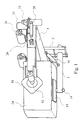
- the apparatus comprises a frame part consisting of at least a vertical support 2 and a supporting beam 1 disposed symmetrically above the frame part 2 and perpendicularly to it, i.e. in a substantially horizontal position.
- a working arm 4 pivotally connected to the beam by its first end and acting as a loading and wrapping arm, which turns laterally about joint 28 and vertically about joint 27.
- the length of the working arm i.e.
- each working arm is a bale holding and rotating mechanism. which consists of a hydraulic motor acting as a rotation means 11, a rotating shaft 12 and a squeeze plate 10 attached to the shaft 12.
- the squeeze plates on the two working arms face toward each other so that, by turning the working arms 4 toward each other, a bale can be gripped between the squeeze plates 10 in order to move it, wrap it with plastic or load it onto a vehicle.
- Placed in the vicinity of the squeeze plates is at least one mechanical detector serving to centralise the squeeze plates with respect to the bale.
- the squeeze plate is connected to its rotating shaft via a ball joint to permit adaptation to a possible wobbling motion of the bale.
- a low supporting arm 3 Connected in a horizontally turnable fashion by its first end to the lower part of the vertical support is a low supporting arm 3, whose other end carries a hydraulic motor 14 and a rotating plate 15 attached to it by a shaft and designed to support the bale from below when the bale is being turned in a horizontal plane between different stages of a wrapping operation, During wrapping, the low supporting arm is held in a lateral position to keep it out of the way when the bale is being rotated in a vertical plane.
- the turning movement of the low supporting arm is implemented using a hydraulic cylinder 16,
- each guide bar Placed above the supporting beam 1 and parallel to it are two guide bars 5 and 6, of which the upper guide bar 5 is attached by its ends to end plates 25 while the lower guide bar 6, which may disposed in a position somewhat closer to the bale, is attached by its ends to end plates 26.
- Slidably mounted on each guide bar is a roll carriage 29 with bearings supporting a wrapping foil roll 7, 8 in a position parallel to the guide bars 5 , 6.
- the roll carriages are designed to be movable on the guide bars from end to end of the bar, the movement being controlled by a logic control system.
- the roll carriage movement is produced by a chain connected to each roll carriage and driven by a hydraulic motor.
- the range of movement of the roll carriages extends so far out that the horizontal distance between the outer ends of the plastic rolls at the beginning of a wrapping operation is larger than the corresponding width of the fodder bale 24 between the squeeze plates 10 of the working arms This arrangement allows a portion of the plastic foil to be bent over the inner corners 22, 23 of the bale at the beginning of the wrapping operation so that no part at the corners of the bale is left uncovered with plastic.
- each squeeze plate 10 mounted in the immediate vicinity of each squeeze plate 10 is a holder and locking device 19a, 19b for the free end of the plastic foil, as well as a cutting device.
- the free end of the plastic foil of each roll will remain secured in the holder, ready for the next wrapping operation.
- the plastic foils are arranged in a crosswise manner so that the free end of the plastic foil of the left-hand plastic roll 7 is held by the right-hand holder 19a while the free end of the plastic foil of the right-hand plastic roll 8 is held by the left-hand holder 19b.
- Bale treatment by the method of the invention is as follows:
- the situation presented in Fig. 2 may be regarded as representing the start of a working cycle.
- the bale 24. held between the squeeze plates 10 of the working arms 4, has been taken up from a field, storage or other suitable place.
- the bale is gripped by its longer sides and the length of the working arms has been adjusted according to the bale length so that the squeeze plates grip the bale at about the centre of the bale side.
- the plastic rolls 7, 8 are driven by the logic control system into a crosswise position as illustrated by Fig. 2. In this situation, the distance between the outer ends of the plastic rolls is greater than the corresponding width dimension of the bale.
- the free ends of the plastic foils are held in their holders 19a, 19b.
- the free end of the plastic foil of the left-hand plastic roll 7 is held by the right-hand holder 19a while the free end of the plastic foil of the right-hand plastic roll 8 is held by the left-hand holder 19b.
- the low supporting arm Before the wrapping operation is started, the low supporting arm must be turned aside to make way for the bale.
- the wrapping process is started by rotating the bale in a vertical plane by means of the rotation means 11.
- the crosswise plastic foils 17, 18 at first go over the inner corners 22, 23 of the bale and are partially bent onto the long sides of the bale From this point, the process can be continued in two different ways.
- a first alternative when the bale has been rotated through a first half-revolution, the plastic rolls are quickly moved crosswise again, the bale is rotated again through half a revolution and the originally outer corners 20, 21 are wrapped. After this, the bale is rotated continuously in a vertical plane while the plastic rolls are slowly driven toward each other, the bale being thus completely wrapped longitudinally until the plastic rolls have reached the midpoint of their range of movement.
- the plastic rolls are immediately driven slowly against each other and the rolls are moved, without rotating the bale, from their mid-position to the extremities of their range of movement, and finally the originally outer corners 20, 21 are wrapped.
- the second phase is started.
- the low supporting arm 3 is driven into position under the bale, the working arms 4 are released from the bale by turning them outward farther apart and the bale is rotated horizontally through 90o by means of the rotating mechanism 14.
- the plastic foils 17, 18 now cross each other again and are bent over the corners 20 and 23.
- the bale is pressed by its ends between the squeeze plates 10 and lifted off the rotating plate 15, whereupon the low supporting arm 3 is turned aside.
- the wrapping operation is finished by rotating the bale transversely between the squeeze plates 10 and moving the plastic rolls on their guide bars either from the middle towards the ends or from the ends towards the middle.
- the plastic rolls are again moved to the ends of their guide bars, whereupon the free ends of the plastic foils fall into the holders 19a, 19b mounted near the other ends of the working arms 4 and are locked in the holders.
- the portion of the plastic foil between the bale and the holder is cut off, leaving the free end of each plastic foil locked in the holder, whereupon the bale can be dropped down from between the squeeze plates.
- the apparatus may be so constructed that the bale itself is not rotated but instead the plastic rolls 7, 8 together with the guide bars 5, 6 and roll carriages 29 are driven in an orbit around the bale.
- the squeeze plates 10 are only used to keep the bale raised during the wrapping operation.
- connected to each working arm are a rotating mechanism and an L-shaped rotating arm with a roll carriage 29 and a plastic roll mounted in its portion parallel to the axis of rotation.
- the portions parallel to the axis of rotation of the rotating arms are placed oppositely to each other and so dimensioned and synchronised with respect to each other that the roll will not touch each other.
- the rotating mechanisms may be so constructed that the path of the plastic rolls around the bale is not necessarily a perfect circle but rather an adapted 'quadrangular orbit.
- the apparatus is provided with a separate chain-operated track attached to the working arms and placed laterally relative to the bale. said track being of a rectangular shape as seen from the side, approximately conforming to the dimensions of the bale.
- the roll carriage travels around the bale along this chain track, remaining at substantially the same distance from the bale all the time.
- This solution has the advantage that the apparatus can be used to wrap bales of different shapes, including shapes other than rectangular.
- control of the wrapping operation can be implemented using e.g. a microprocessor or equivalent.
Landscapes
- Life Sciences & Earth Sciences (AREA)
- Environmental Sciences (AREA)
- Storage Of Harvested Produce (AREA)
- Preliminary Treatment Of Fibers (AREA)
- Wire Bonding (AREA)
- Television Systems (AREA)
- Control Of El Displays (AREA)
- Fodder In General (AREA)
- Apparatuses For Bulk Treatment Of Fruits And Vegetables And Apparatuses For Preparing Feeds (AREA)
Claims (7)
- Procédé pour emballer une balle de foin ou de paille comme une balle de fourrage de blé avec une feuille de plastique dans lequel procédé le dispositif d'emballage est accroché à un tracteur ou à quelque chose d'équivalent ; ledit dispositif d'emballage comprenant des rouleaux de plastique (7, 8) pourvus d'une feuille en plastique, caractérisé en ce que l'opération d'emballage de la balle comprend au moins les étapes suivantes :au début de l'opération d'emballage, la balle est levée dans le dispositif d'emballage en étant agrippée par ses côtés au moyen d'un mécanisme d'agrippage (4, 10) et levée de sa base ;les feuilles de plastique (17, 18) provenant de deux rouleaux de plastique (7, 8) sont destinées de se déplacer d'une manière croisée l'une par rapport à l'autre et passées autour de la balle (24);les deux rouleaux de plastique (7, 8) sont conduits l'un vers l'autre et la balle est emballée dans un plan vertical entre les bras de travail (4) jusqu'à ce que la balle soit entièrement recouverte de plastique ;la balle est retirée du dispositif d'emballage au moyen des bras de travail (4).
- Procédé selon la revendication 1, pour emballer une balle de foin ou de paille comme une balle de fourrage en paille avec une feuille de plastique pendant lequel procédé le dispositif d'emballage est accroché à un tracteur ou quelque chose d'équivalent ; ledit dispositif d'emballage comprenant un élément supportant et tournant la balle (24) ainsi que les rouleaux de plastique (7, 8) pourvus d'une feuille de plastique, caractérisé en ce que l'opération d'emballage de la balle comprend au moins les étapes suivantes :au début de l'opération d'emballage, la balle est levée dans l'appareil d'emballage en étant agrippée par ses côtés grâce à un mécanisme d'agrippage (4, 10) et levée de sa base ;les feuilles en plastique (17, 18) provenant de deux rouleaux en plastique (7, 8) sont destinées à être entraíné d'une manière croisée l'une par rapport à l'autre et la balle (24) est tournée;les deux rouleaux de plastique (7, 8) sont conduits l'un vers l'autre et la balle est tournée dans un plan vertical entre les bras de travail (4) jusqu'à ce que la balle soit entièrement recouverte de plastique ;la balle est retirée du dispositif d'emballage au moyen des bras de travail (4).
- Procédé selon la revendication 1 pour emballer une balle de fourrage en paille avec une feuille de plastique, caractérisé en ce que la balle est levée dans l'appareil d'emballage grâce aux bras de travail (4) en étant pressée par ses longs côtés entre les plaques de serrage (10) pourvues à ses extrémités des bras de travail et levée de sa base et caractérisé en ce que la balle est emballée entre les bras de travail en étant tournée par les plaques de serrage (10) et des moyens de rotation (11) et caractérisé en ce que, si nécessaire, la balle est tournée à 90° du bas grâce à un bras de support inférieur avant le stade final de l'opération d'emballage.
- Dispositif pour emballer une balle de foin ou de paille comme une balle de fourrage en paille avec une feuille de plastique, lequel dispositif comprend un dispositif d'emballage accroché à un tracteur ou à quelque chose d'équivalent, lequel dispositif comprend une partie de cadre (en forme de cadre) (1.2) comprenant des éléments nécessaires pour lever la balle et l'emballer avec une feuille de plastique, caractérisé en ce que le dispositif comprend au moins deux bras de travail (4) articulés par leurs premières extrémités sur la partie supérieure de la partie en forme de cadre de sorte que les bras de travail puissent être tournés l'un vers l'autre; les secondes extrémités desdits bras étant pourvues de plaques de serrage (10) destinées à tenir la balle et caractérisé en ce que la partie en forme de cadre est pourvue en plus de rouleaux de plastique (7, 8) qui peuvent être conduits dans des directions opposées l'un par rapport à l'autre et qui sont destinés à être déplacés dans des directions opposées de manière à ce que les feuilles de plastique provenant des rouleaux de plastique et entourées autour de la balles se croisent pendant l'opération d'emballage.
- Dispositif selon la revendication 4 pour emballer une balle de foin ou de paille telle une balle de fourrage en paille avec une feuille de plastique, caractérisé en ce que le dispositif comprend au moins deux bras de travail (4) articulés par leurs premières extrémités sur la partie supérieure de la partie en forme de cadre de sorte que les bras de travail puissent être tournés l'un vers l'autre; les secondes extrémités desdits bras de travail étant pourvues de plaques de serrage (10) pour tourner les balles et caractérisé en ce que la partie en forme de cadre est pourvue en plus de rouleaux de plastique (7, 8) qui peuvent être conduits dans des directions opposées l'un par rapport à l'autre et qui sont destinés à être déplacés dans des directions opposées de sorte que les feuilles de plastique provenant des rouleaux de plastique et enroulées autour de la balle se croisent pendant l'opération d'emballage.
- Dispositif selon la revendication 4 ou 5, caractérisé en ce que la première extrémité de chaque bras de travail (4) est connectée à l'extrémité de la poutre de support (1) dans la partie supérieure de la partie en forme de cadre par un élément de connexion qui permet au bras de travail de les faire tourner tous les deux de manière horizontale et verticale.
- Dispositif selon la revendication 5 ou 6, caractérisé en ce que le dispositif d'emballage comprend un bras de support inférieur ( 3) monté dans la partie inférieure de la partie en forme de cadre ; l'autre extrémité du bras de support inférieur étant pourvu d'un mécanisme de rotation (14, 15) pour tourner la balle et la supporter par le bas.
Applications Claiming Priority (3)
| Application Number | Priority Date | Filing Date | Title |
|---|---|---|---|
| FI974137 | 1997-11-04 | ||
| FI974137A FI105393B (fi) | 1997-11-04 | 1997-11-04 | Menetelmä ja laitteisto rehupaalin muovittamiseksi |
| PCT/FI1998/000845 WO1999022583A1 (fr) | 1997-11-04 | 1998-10-30 | Procede et appareil de manipulation d'une balle de fourrage |
Publications (2)
| Publication Number | Publication Date |
|---|---|
| EP1028614A1 EP1028614A1 (fr) | 2000-08-23 |
| EP1028614B1 true EP1028614B1 (fr) | 2002-04-03 |
Family
ID=8549868
Family Applications (1)
| Application Number | Title | Priority Date | Filing Date |
|---|---|---|---|
| EP98952761A Expired - Lifetime EP1028614B1 (fr) | 1997-11-04 | 1998-10-30 | Procede et appareil de manipulation d'une balle de fourrage |
Country Status (8)
| Country | Link |
|---|---|
| EP (1) | EP1028614B1 (fr) |
| AT (1) | ATE215304T1 (fr) |
| AU (1) | AU1033699A (fr) |
| CA (1) | CA2307569C (fr) |
| DE (1) | DE69804654T2 (fr) |
| DK (1) | DK1028614T3 (fr) |
| FI (1) | FI105393B (fr) |
| WO (1) | WO1999022583A1 (fr) |
Families Citing this family (7)
| Publication number | Priority date | Publication date | Assignee | Title |
|---|---|---|---|---|
| FI111455B (fi) * | 2000-09-04 | 2003-07-31 | Wrapmatic Oy | Menetelmä ja laitteisto kappaleen muovittamiseksi |
| NL2004611C2 (nl) * | 2010-04-26 | 2011-10-27 | Knoll Geb | Inrichting voor het met een folie omwikkelen van een baal maaigoed en combinatie daarvan met een balenpers. |
| GB201014033D0 (en) | 2010-08-20 | 2010-10-06 | Ucb Pharma Sa | Biological products |
| CA2906954A1 (fr) * | 2013-03-15 | 2014-09-18 | Groupe Anderson Inc. | Dispositif d'emballage et son procede d'utilisation |
| US11006581B2 (en) | 2017-03-03 | 2021-05-18 | Deere & Company | Bale wrap mechanism |
| US10765068B2 (en) | 2017-03-03 | 2020-09-08 | Deere & Company | Bale wrap mechanism |
| US11013183B2 (en) | 2017-03-03 | 2021-05-25 | Deere & Company | Bale wrap mechanism |
Family Cites Families (2)
| Publication number | Priority date | Publication date | Assignee | Title |
|---|---|---|---|---|
| US4343132A (en) * | 1979-12-28 | 1982-08-10 | Lawless Jr Joseph F | Bale wrapping device and method |
| GB9411227D0 (en) * | 1994-06-04 | 1994-07-27 | Kverneland Underhaug As | Bale wrapping apparatus |
-
1997
- 1997-11-04 FI FI974137A patent/FI105393B/fi not_active IP Right Cessation
-
1998
- 1998-10-30 CA CA002307569A patent/CA2307569C/fr not_active Expired - Lifetime
- 1998-10-30 EP EP98952761A patent/EP1028614B1/fr not_active Expired - Lifetime
- 1998-10-30 AT AT98952761T patent/ATE215304T1/de not_active IP Right Cessation
- 1998-10-30 AU AU10336/99A patent/AU1033699A/en not_active Abandoned
- 1998-10-30 DK DK98952761T patent/DK1028614T3/da active
- 1998-10-30 WO PCT/FI1998/000845 patent/WO1999022583A1/fr not_active Ceased
- 1998-10-30 DE DE69804654T patent/DE69804654T2/de not_active Expired - Lifetime
Also Published As
| Publication number | Publication date |
|---|---|
| FI974137A0 (fi) | 1997-11-04 |
| ATE215304T1 (de) | 2002-04-15 |
| EP1028614A1 (fr) | 2000-08-23 |
| DE69804654D1 (de) | 2002-05-08 |
| AU1033699A (en) | 1999-05-24 |
| WO1999022583A1 (fr) | 1999-05-14 |
| CA2307569C (fr) | 2007-05-15 |
| CA2307569A1 (fr) | 1999-05-14 |
| FI974137L (fi) | 1999-05-05 |
| FI105393B (fi) | 2000-08-15 |
| DK1028614T3 (da) | 2002-07-29 |
| DE69804654T2 (de) | 2002-10-17 |
Similar Documents
| Publication | Publication Date | Title |
|---|---|---|
| EP0234763B1 (fr) | Dispositif pour emballer des articles cylindriques | |
| CA1250800A (fr) | Machine pour envelopper les balles cylindriques | |
| US8230663B2 (en) | Baler and wrapper combination | |
| US4835836A (en) | Device for the cutting and removal of the strapping bands from an object | |
| JP3415842B2 (ja) | 物品の包装方法及び装置 | |
| US5740662A (en) | Bale wrapper apparatus | |
| CA2205069A1 (fr) | Ramasseuse-presse avec dispositif d'emballage de balle a bras plongeant | |
| CA2217075A1 (fr) | Machine d'emballage de balles | |
| EP0652700A1 (fr) | Appareil d'empaquetage de balles | |
| CA2307569C (fr) | Procede et appareil de manipulation d'une balle de fourrage | |
| US5224323A (en) | Bale wrapper apparatus | |
| AU2006200543B2 (en) | Round bale wrapper | |
| WO1990014756A1 (fr) | Appareil pour l'emballage de balles | |
| WO1996012399A1 (fr) | Procede et appareil permettant d'emballer de plastique une balle de fourrage | |
| WO1994017653A1 (fr) | Appareil d'emballage de balles de fourrage | |
| CA2270101A1 (fr) | Machine d'enrubannage en ligne munie d'un organe de reglage de soutien incline | |
| EP0499285B1 (fr) | Appareil pour envelopper des balles de fourage avec du plastic | |
| GB2275037A (en) | Bale wrapper apparatus | |
| EP0427039A1 (fr) | Machine pour envelopper des balles de fourrage ou analogues | |
| JP7524042B2 (ja) | ラッピングマシン | |
| US4019309A (en) | Round bale forming machine | |
| EP1322147B1 (fr) | Procede d'emballage d'articles avec une matiere plastique et appareil a cet effet | |
| US20040177597A1 (en) | Bale wrapping method and apparatus | |
| GB2394932A (en) | Bale wrapping machine | |
| KR101550794B1 (ko) | 베일 포장기의 베일 세움 구조 |
Legal Events
| Date | Code | Title | Description |
|---|---|---|---|
| PUAI | Public reference made under article 153(3) epc to a published international application that has entered the european phase |
Free format text: ORIGINAL CODE: 0009012 |
|
| 17P | Request for examination filed |
Effective date: 20000531 |
|
| AK | Designated contracting states |
Kind code of ref document: A1 Designated state(s): AT BE CH DE DK FR GB IE LI NL SE |
|
| GRAG | Despatch of communication of intention to grant |
Free format text: ORIGINAL CODE: EPIDOS AGRA |
|
| 17Q | First examination report despatched |
Effective date: 20010807 |
|
| GRAG | Despatch of communication of intention to grant |
Free format text: ORIGINAL CODE: EPIDOS AGRA |
|
| GRAH | Despatch of communication of intention to grant a patent |
Free format text: ORIGINAL CODE: EPIDOS IGRA |
|
| REG | Reference to a national code |
Ref country code: GB Ref legal event code: IF02 |
|
| GRAH | Despatch of communication of intention to grant a patent |
Free format text: ORIGINAL CODE: EPIDOS IGRA |
|
| GRAA | (expected) grant |
Free format text: ORIGINAL CODE: 0009210 |
|
| AK | Designated contracting states |
Kind code of ref document: B1 Designated state(s): AT BE CH DE DK FR GB IE LI NL SE |
|
| PG25 | Lapsed in a contracting state [announced via postgrant information from national office to epo] |
Ref country code: NL Free format text: LAPSE BECAUSE OF FAILURE TO SUBMIT A TRANSLATION OF THE DESCRIPTION OR TO PAY THE FEE WITHIN THE PRESCRIBED TIME-LIMIT Effective date: 20020403 Ref country code: LI Free format text: LAPSE BECAUSE OF FAILURE TO SUBMIT A TRANSLATION OF THE DESCRIPTION OR TO PAY THE FEE WITHIN THE PRESCRIBED TIME-LIMIT Effective date: 20020403 Ref country code: CH Free format text: LAPSE BECAUSE OF FAILURE TO SUBMIT A TRANSLATION OF THE DESCRIPTION OR TO PAY THE FEE WITHIN THE PRESCRIBED TIME-LIMIT Effective date: 20020403 Ref country code: BE Free format text: LAPSE BECAUSE OF FAILURE TO SUBMIT A TRANSLATION OF THE DESCRIPTION OR TO PAY THE FEE WITHIN THE PRESCRIBED TIME-LIMIT Effective date: 20020403 Ref country code: AT Free format text: LAPSE BECAUSE OF FAILURE TO SUBMIT A TRANSLATION OF THE DESCRIPTION OR TO PAY THE FEE WITHIN THE PRESCRIBED TIME-LIMIT Effective date: 20020403 |
|
| REF | Corresponds to: |
Ref document number: 215304 Country of ref document: AT Date of ref document: 20020415 Kind code of ref document: T |
|
| REG | Reference to a national code |
Ref country code: CH Ref legal event code: EP |
|
| REF | Corresponds to: |
Ref document number: 69804654 Country of ref document: DE Date of ref document: 20020508 |
|
| REG | Reference to a national code |
Ref country code: IE Ref legal event code: FG4D |
|
| REG | Reference to a national code |
Ref country code: DK Ref legal event code: T3 |
|
| NLV1 | Nl: lapsed or annulled due to failure to fulfill the requirements of art. 29p and 29m of the patents act | ||
| ET | Fr: translation filed | ||
| REG | Reference to a national code |
Ref country code: CH Ref legal event code: PL |
|
| PLBE | No opposition filed within time limit |
Free format text: ORIGINAL CODE: 0009261 |
|
| STAA | Information on the status of an ep patent application or granted ep patent |
Free format text: STATUS: NO OPPOSITION FILED WITHIN TIME LIMIT |
|
| 26N | No opposition filed |
Effective date: 20030106 |
|
| REG | Reference to a national code |
Ref country code: FR Ref legal event code: PLFP Year of fee payment: 18 |
|
| REG | Reference to a national code |
Ref country code: FR Ref legal event code: PLFP Year of fee payment: 19 |
|
| REG | Reference to a national code |
Ref country code: FR Ref legal event code: PLFP Year of fee payment: 20 |
|
| PGFP | Annual fee paid to national office [announced via postgrant information from national office to epo] |
Ref country code: FR Payment date: 20171024 Year of fee payment: 20 Ref country code: DK Payment date: 20171019 Year of fee payment: 20 Ref country code: DE Payment date: 20171019 Year of fee payment: 20 |
|
| PGFP | Annual fee paid to national office [announced via postgrant information from national office to epo] |
Ref country code: GB Payment date: 20171019 Year of fee payment: 20 Ref country code: IE Payment date: 20171025 Year of fee payment: 20 Ref country code: SE Payment date: 20171019 Year of fee payment: 20 |
|
| REG | Reference to a national code |
Ref country code: DE Ref legal event code: R071 Ref document number: 69804654 Country of ref document: DE |
|
| REG | Reference to a national code |
Ref country code: DK Ref legal event code: EUP Effective date: 20181030 |
|
| REG | Reference to a national code |
Ref country code: GB Ref legal event code: PE20 Expiry date: 20181029 |
|
| REG | Reference to a national code |
Ref country code: IE Ref legal event code: MK9A |
|
| REG | Reference to a national code |
Ref country code: SE Ref legal event code: EUG |
|
| PG25 | Lapsed in a contracting state [announced via postgrant information from national office to epo] |
Ref country code: IE Free format text: LAPSE BECAUSE OF EXPIRATION OF PROTECTION Effective date: 20181030 |
|
| PG25 | Lapsed in a contracting state [announced via postgrant information from national office to epo] |
Ref country code: GB Free format text: LAPSE BECAUSE OF EXPIRATION OF PROTECTION Effective date: 20181029 |