EP1029183B1 - Machine hydraulique - Google Patents
Machine hydraulique Download PDFInfo
- Publication number
- EP1029183B1 EP1029183B1 EP98957830A EP98957830A EP1029183B1 EP 1029183 B1 EP1029183 B1 EP 1029183B1 EP 98957830 A EP98957830 A EP 98957830A EP 98957830 A EP98957830 A EP 98957830A EP 1029183 B1 EP1029183 B1 EP 1029183B1
- Authority
- EP
- European Patent Office
- Prior art keywords
- pump
- motor
- torque
- displacement
- hydraulic
- Prior art date
- Legal status (The legal status is an assumption and is not a legal conclusion. Google has not performed a legal analysis and makes no representation as to the accuracy of the status listed.)
- Expired - Lifetime
Links
- 230000005540 biological transmission Effects 0.000 claims abstract description 122
- 230000002706 hydrostatic effect Effects 0.000 claims abstract description 29
- 238000006073 displacement reaction Methods 0.000 claims description 79
- 239000012530 fluid Substances 0.000 claims description 74
- 230000007935 neutral effect Effects 0.000 claims description 17
- 238000006243 chemical reaction Methods 0.000 claims description 10
- 230000036316 preload Effects 0.000 claims description 6
- 230000008859 change Effects 0.000 claims description 5
- 238000005461 lubrication Methods 0.000 claims description 5
- 238000007789 sealing Methods 0.000 claims description 2
- 238000001816 cooling Methods 0.000 claims 1
- 238000010079 rubber tapping Methods 0.000 claims 1
- 230000008901 benefit Effects 0.000 description 10
- 230000001133 acceleration Effects 0.000 description 7
- 230000006870 function Effects 0.000 description 7
- 238000013459 approach Methods 0.000 description 6
- 238000013461 design Methods 0.000 description 6
- 239000007858 starting material Substances 0.000 description 6
- 230000007423 decrease Effects 0.000 description 5
- 241000894007 species Species 0.000 description 4
- 230000007246 mechanism Effects 0.000 description 3
- 238000000034 method Methods 0.000 description 3
- 230000002093 peripheral effect Effects 0.000 description 3
- 238000005086 pumping Methods 0.000 description 3
- 230000009467 reduction Effects 0.000 description 3
- 238000009987 spinning Methods 0.000 description 3
- 230000003044 adaptive effect Effects 0.000 description 2
- 230000008878 coupling Effects 0.000 description 2
- 238000010168 coupling process Methods 0.000 description 2
- 238000005859 coupling reaction Methods 0.000 description 2
- 230000000994 depressogenic effect Effects 0.000 description 2
- 238000010586 diagram Methods 0.000 description 2
- 230000000694 effects Effects 0.000 description 2
- 238000007667 floating Methods 0.000 description 2
- 230000006872 improvement Effects 0.000 description 2
- 238000012986 modification Methods 0.000 description 2
- 230000004048 modification Effects 0.000 description 2
- 238000012544 monitoring process Methods 0.000 description 2
- 230000008569 process Effects 0.000 description 2
- 230000011664 signaling Effects 0.000 description 2
- 238000012546 transfer Methods 0.000 description 2
- 208000012661 Dyskinesia Diseases 0.000 description 1
- 241000289581 Macropus sp. Species 0.000 description 1
- 239000011324 bead Substances 0.000 description 1
- 238000002485 combustion reaction Methods 0.000 description 1
- 238000010276 construction Methods 0.000 description 1
- 238000005516 engineering process Methods 0.000 description 1
- 238000004519 manufacturing process Methods 0.000 description 1
- 230000001172 regenerating effect Effects 0.000 description 1
- 238000013341 scale-up Methods 0.000 description 1
Images










Classifications
-
- F—MECHANICAL ENGINEERING; LIGHTING; HEATING; WEAPONS; BLASTING
- F16—ENGINEERING ELEMENTS AND UNITS; GENERAL MEASURES FOR PRODUCING AND MAINTAINING EFFECTIVE FUNCTIONING OF MACHINES OR INSTALLATIONS; THERMAL INSULATION IN GENERAL
- F16H—GEARING
- F16H61/00—Control functions within control units of change-speed- or reversing-gearings for conveying rotary motion ; Control of exclusively fluid gearing, friction gearing, gearings with endless flexible members or other particular types of gearing
- F16H61/38—Control of exclusively fluid gearing
- F16H61/40—Control of exclusively fluid gearing hydrostatic
- F16H61/42—Control of exclusively fluid gearing hydrostatic involving adjustment of a pump or motor with adjustable output or capacity
-
- F—MECHANICAL ENGINEERING; LIGHTING; HEATING; WEAPONS; BLASTING
- F16—ENGINEERING ELEMENTS AND UNITS; GENERAL MEASURES FOR PRODUCING AND MAINTAINING EFFECTIVE FUNCTIONING OF MACHINES OR INSTALLATIONS; THERMAL INSULATION IN GENERAL
- F16H—GEARING
- F16H47/00—Combinations of mechanical gearing with fluid clutches or fluid gearing
- F16H47/02—Combinations of mechanical gearing with fluid clutches or fluid gearing the fluid gearing being of the volumetric type
- F16H47/04—Combinations of mechanical gearing with fluid clutches or fluid gearing the fluid gearing being of the volumetric type the mechanical gearing being of the type with members having orbital motion
-
- F—MECHANICAL ENGINEERING; LIGHTING; HEATING; WEAPONS; BLASTING
- F16—ENGINEERING ELEMENTS AND UNITS; GENERAL MEASURES FOR PRODUCING AND MAINTAINING EFFECTIVE FUNCTIONING OF MACHINES OR INSTALLATIONS; THERMAL INSULATION IN GENERAL
- F16H—GEARING
- F16H37/00—Combinations of mechanical gearings, not provided for in groups F16H1/00 - F16H35/00
- F16H37/02—Combinations of mechanical gearings, not provided for in groups F16H1/00 - F16H35/00 comprising essentially only toothed or friction gearings
- F16H37/06—Combinations of mechanical gearings, not provided for in groups F16H1/00 - F16H35/00 comprising essentially only toothed or friction gearings with a plurality of driving or driven shafts; with arrangements for dividing torque between two or more intermediate shafts
- F16H37/08—Combinations of mechanical gearings, not provided for in groups F16H1/00 - F16H35/00 comprising essentially only toothed or friction gearings with a plurality of driving or driven shafts; with arrangements for dividing torque between two or more intermediate shafts with differential gearing
- F16H37/0833—Combinations of mechanical gearings, not provided for in groups F16H1/00 - F16H35/00 comprising essentially only toothed or friction gearings with a plurality of driving or driven shafts; with arrangements for dividing torque between two or more intermediate shafts with differential gearing with arrangements for dividing torque between two or more intermediate shafts, i.e. with two or more internal power paths
- F16H37/084—Combinations of mechanical gearings, not provided for in groups F16H1/00 - F16H35/00 comprising essentially only toothed or friction gearings with a plurality of driving or driven shafts; with arrangements for dividing torque between two or more intermediate shafts with differential gearing with arrangements for dividing torque between two or more intermediate shafts, i.e. with two or more internal power paths at least one power path being a continuously variable transmission, i.e. CVT
- F16H2037/0866—Power-split transmissions with distributing differentials, with the output of the CVT connected or connectable to the output shaft
-
- F—MECHANICAL ENGINEERING; LIGHTING; HEATING; WEAPONS; BLASTING
- F16—ENGINEERING ELEMENTS AND UNITS; GENERAL MEASURES FOR PRODUCING AND MAINTAINING EFFECTIVE FUNCTIONING OF MACHINES OR INSTALLATIONS; THERMAL INSULATION IN GENERAL
- F16H—GEARING
- F16H2200/00—Transmissions for multiple ratios
- F16H2200/20—Transmissions using gears with orbital motion
- F16H2200/2002—Transmissions using gears with orbital motion characterised by the number of sets of orbital gears
- F16H2200/2007—Transmissions using gears with orbital motion characterised by the number of sets of orbital gears with two sets of orbital gears
Definitions
- This invention relates to hydromechanical transmissions, and more particularly to a hydromechanical transmission having rotating cylinder block hydrostatic units on each side of a grounded manifold and related through two planetary gear sets, and a simple clutch for selectively decoupling the pump from the input shaft, and to facilitate ease of external access to the fluid circuit without need of rotating fluid interfaces.
- Hydromechanical transmissions of many varieties have been conceived, although only a small number have actually been produced in commercial quantities. Many practical engineering problems must be addressed before a transmission would be considered acceptable for use in a production vehicle.
- One such problem is dynamic balancing of rotating components. In large machines with low input and output speeds, dynamic balancing is not a critical factor, but in modern passenger cars where the trend is toward higher engine speeds, dynamic balance becomes increasingly important since the unbalance forces are proportional to the square of the rotating velocity. Therefore, all serious engineering designs for such applications must provide for dynamic balance of rotating components, typically by some form of translating counterbalance mass. Complicating the issue, it may be difficult to design a system that is well balanced dynamically over its entire range of operating speeds. Thus, a hydromechanical transmission having components that are inherently dynamically balanced over their full range of operating speeds would be a significant improvement to the technology of hydromechanical transmissions.
- the speed and torque range of the transmission must be tailored precisely to the requirements of the driven application and the capabilities of the driver.
- modern passenger cars generally have an over-drive top gear with a ratio of approximately 0.7:1 and a low gear ratio of approximately 3:1 for a range spread of greater than 4:1.
- An ideal transmission would make it possible to cover this entire range without the need to shift gears, using hydraulic units large enough to develop the 3:1 low gear multiplication.
- the flow rate in conventional hydrostatic transmission is a source of fluid flow losses and noise.
- a hydromechanical transmission that greatly reduces the fluid flow rate compared to that in conventional hydrostatic CVTs would offer a significant advantage in efficiency and noise.
- the flow rate at neutral and at final ratio can be reduced to zero regardless of power throughput, and if the maximum flow is only 1/3 that of conventional hydrostatic transmissions of the same displacement, that improvement would be very welcome in the industry.
- a continuously variable transmission as defined in the preamble of claim 1 is known from US-A-3,132,534 .
- hydromechanical transmission range from large power plants on the order of railroad engines, marine engines and off road loaders and trucks, all the way down to snowmobiles, motorcycles, and even electric scooters.
- a high input shaft speed often needs to be geared down to produce a moderate pump speed at an elevated torque to better match the input speed to the pump characteristics.
- a clutch or brake mechanism that can be operated to smoothly decouple the input shaft from the pump would be a useful feature to reduce the start-up torque, eliminate lurching on start-up, and provide a soft "launch feel", that is, a smoothly operating, easily controlled acceleration from stand-still without lurching, jerking or lunging.
- an object of this invention to provide an improved hydromechanical transmission having an internal clutch mechanism for decoupling the input shaft from the pump to allow the transmission to free-wheel during start-up and other suitable times during operation of the vehicle.
- a continuously variable transmission as defined in independent claim 1, having an operating assembly including an input hydrostatic unit driven by an input shaft, and an output hydrostatic unit hydraulically related to the input hydrostatic unit through a stationary manifold between rotating cylinder blocks of the two units.
- the input and output hydrostatic units are mechanically related to each other and to the input shaft and an output shaft through at least one variable ratio or epicyclic gearset such as a planetary gearset or differential gearset, all enclosed within a housing.
- a stationary actuator fixed to the housing is linked to the hydrostatic units for adjusting their displacement, and that actuator is controlled by a control mechanism that causes the actuator to shift to positions that produce the desired transmission ratio.
- a brake is interposed between two elements in the gearset for selectively and smoothly decoupling and recoupling the input hydrostatic unit from the input shaft to allow the transmission to free-wheel when the brake is operated.
- Fig. 1 the invention is illustrated in a schematic diagram in its preferred embodiment as a serial, continuously variable, double planetary design. It is specifically intended for use in most bus, truck and automobile applications powered by diesel and gasoline internal combustion engines 40 where an overdrive final ratio is specified, although it would be useful in many other applications as well.
- the transmission is shown in Fig. 1 at hydraulic lock-up, with an input hydrostatic unit, or pump 50, at maximum displacement and the output hydrostatic unit, or motor 60, at zero displacement.
- the pump 50 has a non-rotating element and a rotating element driven by input torque delivered from an input shaft 65, and is effective to pressurize a working fluid such as hydraulic fluid.
- the motor 60 produces output torque delivered to an output shaft 76 when the motor is energized by the pressurized fluid from the pump 50.
- the two hydrostatic units can be simultaneously controlled from a master controller 100, or they can be independently controlled, as described in detail below.
- Rotary power from the engine 40 is delivered, typically directly from the engine crankshaft to a drive coupling 64 at the input end of the input shaft 65 of the transmission at the speed and torque of the engine 40, which can be operated at its optimum operating point for optimal efficiency and emissions.
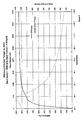
- the transmission has a continuously variable ratio that enables it to convert the rotary input power from the engine 40 to rotary output power to the vehicle drive shaft at any desired speed within a range from reverse, through zero, to an overdrive speed, for example 1.5 times engine speed, and at a corresponding torque, with an overall efficiency of about 90% or higher, as shown in Fig. 2.
- Input torque from the engine 40 is transmitted through the input shaft 65 to a planet carrier 67 of a motor planet gear set 70 having planet gears 72 mounted in the planet carrier 67 and engaged with an inner sun gear 73 and an outer ring gear 74.
- the input shaft 65 also drives a makeup pump 75 mounted in a front end closure of the transmission case.
- the ring gear 74 of the motor planet set 70 is connected drivingly to the motor 60 and to an output shaft 76.
- a torque tube 78 connects the sun gear 73 of the motor planet 70 set to a sun gear 83 of a pump planet set 80.
- the pump planet gear set has a pump planet carrier 77 in which are mounted pump planet gears 82 that are engaged with the inner pump sun gear 83 and an outer pump ring gear 84.
- the ring gear 84 of the pump planet set 80 is connected drivingly to the pump 50.
- the planet carrier 77 of the pump planet set 80 can be grounded to the transmission case via a releasable brake 85.
- the planet carrier 67 of the motor planet set 70 is spinning at input speed and therefore the sun gear 73 of the motor planet set 70 (and hence the sun gear 83 of the pump planet set 80) is rotating at 1+ (Rm/Sm) multiplied by the input speed, where Rm is the number of teeth in the motor set ring gear 74 and Sm is the number of teeth in the motor set sun gear 73.
- Rm is the number of teeth in the motor set ring gear 74
- Sm is the number of teeth in the motor set sun gear 73.
- the ring gear 84 of the pump planet set 80 (hence the pump 50) is driven to rotate at a speed equal to the speed of the sun gears 73 and 83 multiplied by (Sp/Rp) in the opposite direction, where Sp is the number of teeth on the pump set sun gear 83 and Rp is the number of teeth on the pump set ring gear.
- Sp is the number of teeth on the pump set sun gear 83
- Rp is the number of teeth on the pump set ring gear.
- the pump set sun gear 83 has 24 teeth and the pump set ring gear 84 has 64 teeth
- the pump set ring gear 84 and hence the pump will be rotating at sun gear speed multiplied by -(24/64), or 9/8 input speed in the opposite direction from input. Since the pump is at zero displacement, there is no pumping and therefore no reaction torque can be generated at the pump. Hence it rotates freely and the transmission output speed is zero.
- the brake 85 will be released before the engine is turned on, disengaging the pump planet carrier 77 of the pump planet set 80 from ground, so the planet carrier 77 can rotate freely. Therefore, no torque can be transmitted from the sun gear 83 to the pump 50. Without reaction torque transmitted back through the sun gears 83/73, no reaction torque can be transmitted from the input shaft 65 to the output shaft 76, even if the pump is at some displacement when the engine 40 is first turned on. The brake 85 will not be applied until the control has moved the pump to zero displacement, as verified via a sensor signal to the controller 100.
- the input torque is split into two parallel paths, as shown in Fig. 3.
- the first path is a direct mechanical path fed continually to the output shaft at the ratio of input torque multiplied by the inverse of 1 + the ratio of teeth on the motor set sun gear 73 and the motor set ring gear 74, or (1/(1+(Sm/Rm))).
- the second path is a mechanical path fed continually to the pump 50 at a torque equal to the input torque multiplied by the inverse of 1 + the product of the ratios of the numbers of teeth on the motor set ring gear 74 to the sun gear 73, and the numbers of teeth on the pump set ring gear 84 to the sun gear 83, or (1/(1+(Rm/Sm)) x Rp/Sp).
- the pump 50 With the brake 85 applied, grounding the pump gear set planet carrier 77 to the housing, the pump 50 is stroked from zero displacement to give a small displacement.
- the pump 50 is rotated by the input shaft 65, acting through the two planetary gear sets 70 and 80, at input speed multiplied by (1+ (Rm/Sm)) x (Sp/Rp) to begin pumping.
- Fluid displaced by the pump flows directly through flow channels 90 or 95 and drives the motor to produce output torque in the output shaft 76 for delivery through an output drive connection 96 on the output shaft 76 to a drive shaft of the vehicle. Since the pump 50 is at a small displacement, a small amount of torque to the pump 50 results in a high pressure and small flow rate, as shown in Fig. 4.
- Output torque input torque ⁇ 1 / 1 + Sm / Rm + 1 / 1 + Rm / Sm ⁇ Rp / Sp ⁇ motor displacement / pump displacement
- the pump speed approaches zero and motor speed approaches its maximum.
- the motor 60 reaches zero displacement, it can no longer accept fluid flow from the pump 50, so the pump 50 can no longer displace fluid and therefore stops rotating.
- the pump 50 now acts as a reaction unit for the sun gear 73 of the motor planet set 70.
- all the input torque now transfers through the motor planet set 70 to the output shaft 76. Due to the ratio of the sun gear 73 to the ring gear 74 of the motor planet set 70, the output speed increases and the output torque decreases (e.g.
- a brake could be applied to lock the pump 50 to ground. This will help in two ways: first it will stop the pump 50 from slipping due to hydraulic leakage, and second, it will reduce the hydraulic system pressure to makeup pressure, therefore reducing the load and hence windage loss of the motor.
- the pump brake could be actuated by makeup pressure or by electro-mechanical means.
- the transmission can drive the output shaft 76 in reverse.
- a double planetary system (a motor planet set and a pump planet set) in a hydromechanical transmission has numerous benefits over a single planet set, including the following:
- the transmission is controlled by means of the electronic control unit 100.
- the electronic control unit 100 receives several electronic signals from the engine, transmission and vehicle, as shown in Fig. 1.
- the electronic control unit 100 processes these signals using a computer algorithm, specific to each particular vehicle, to produce a control signal which it sends to a transmission ratio control unit 105 having electro-hydraulic devices, such as a servomotor or stepper motor 110 operating a pump modulation valve 115, and a control cylinder 116 by which the output ratio and speed of the transmission are controlled.
- This method of control offers great flexibility and enables the transmission to select the optimum ratio to achieve maximum system performance under a variety of operating conditions.
- the transmission behave in an adaptive, transparent manner, by reading many vehicle sensors such as applied brake force, steering angle, engine torque, rate of change of throttle position as well as throttle position etc. It is also possible to add manual features allowing the operator to select certain ratios.
- the electronic control unit 100 receives signals from the drive switch 118, throttle position sensor, input speed sensor 112, output speed sensor 114, and other sensors selected by the vehicle manufacturer, depending on the desired control sophistication. It processes these input signals and sends signals to the brake modulation valve 97 and the stepper motor 110 for controlling the pump modulation valve 115 by which the control valve 116 is operated to control the displacement of the pump 50 and the motor 60.
- a mechanical safety interlock may be incorporated into the drive switch 118 so that park, reverse and drive can only be selected when the vehicle is stopped or the brakes are applied, and the vehicle may only be started when the vehicle is in park, as in current automatic transmissions.
- the engine is started with the transmission in park.
- the controller 100 receives a signal from a contact in the drive selector switch 118 when the engine ignition switch is operated which signals the controller 100 to de-energize or release the brake 85, which allows the engine crankshaft to rotate without driving the pump 50.
- the electronic control unit 100 also sends a signal to the stepper motor 110 to send the transmission to the neutral position, just in case the vehicle was stopped with the transmission in a ratio other than neutral.
- the make up pump 75 produces enough pressure and flow to ensure that the hydraulic units 50 and 60 have stroked to their neutral position, and pressure is available to energize the hydraulic brake 85 by way of the brake modulation valve 97, and to sufficient lubrication pressure and flow or prevent damage to moving parts.
- Position sensors are attached to the non-rotating elements of the hydraulic units to generate signals that are transmitted to the electronic control unit 100 that the transmission is in neutral (i.e. pump at zero displacement, motor at maximum displacement), thus adding another level of control, safety, and reliability.
- the drive selector switch 118 is moved to the "drive" mode.
- the electronic control unit 100 signals the brake modulation valve 97 to gradually apply the hydraulic brake 85 while also signaling the stepper motor 110 of the transmission ration controller 105 to stroke the transmission to some forward ratio.
- the electronic control unit 100 can determine the required 'take off' characteristic of the vehicle, i.e. whether acceleration is to be slow and soft, hard and fast, or high torque (as in towing) from the rate of depression or force on the accelerator pedal and the load or resisting torque in the output shaft 76.
- the desired "take-off” is achieved by the rate of application of the brake 85 and the rate of change of the speed ratio produced by the stepper motor 110.
- the electronic control unit 100 signals the brake modulation valve 97 to apply full brake force and fully lock the pump planet carrier 77.
- the stepper motor 110 alone now controls all transmission ratios.
- the electronic control unit 100 can produce the required vehicle speed requested by the operator. By comparing these values to a preprogrammed operating schedule the electronic control unit 100 can vary the transmission ratio (via the stepper motor 110) to achieve the most effective driving regime. By comparing the input to output speed signals the electronic control unit 100 can determine the transmission ratio and make continual changes to the stepper motor 110 to achieve this regime. It is also possible to add a driving style switch, such as sport or economy mode, to enable the electronic control unit 100 to read different operating schedules and therefore give different driving conditions as requested by the operator, enabling the electronic control unit 100 to select the most efficient ratio for greatest economy, or achieving the highest performance for acceleration etc.
- a driving style switch such as sport or economy mode
- a small dump (short circuit) valve 117 may be inserted between the high-pressure and low-pressure lines 90 and 95 of the hydraulic units 50 and 60, allowing the hydraulic motor 60 to 'freewheel'.
- the dump valve 117 can be operated electronically and actuated by the electronic control unit 100 just before the neutral position is achieved.
- the dump valve 117 need only accept a small flow rate as the motor speed will be virtually zero at this point. Once the vehicle is stopped the electronic control unit 100 can close the dump valve 117 and return the transmission to its 'holding neutral' position.
- the electronic control unit 100 may be programmed to de-energize the brake modulation valve 97 therefore releasing the pump planet carrier 77. Although this is not necessary for the transmission to stay in the neutral mode, it readies the transmission for the next launch.
- the level of sophistication of control can be increased by using the variety of now common vehicle sensors, and more complex computer algorithms to achieve an adaptive transmission control, monitoring the driver's inputs and continually updating the operating schedules.
- the electronic control unit 100 can perform system diagnostic checks, by comparing the feedback signal from the servomotor or stepper motor 110 and actual ratio achieved and/or by measuring system and make up pressures and alerting the driver if these values fall beyond predetermined specifications.
- a low gear position is provided on the drive selector switch 118. This low gear mode can be activated either from a stationary start or on the fly from the drive mode. If low gear is selected from the park position, the transmission will start in the same manner as in drive mode, except that the transmission will not stroke beyond a predetermined ratio, staying at this lower maximum ratio if the throttle position is sufficiently depressed.
- the electronic control unit 100 will also use a different operating schedule to determine the transmission ratio, as starting in low gear will signify that a low speed, high torque demand is required, as in towing and maneuvering a heavy object. Also when driving in the low gear, due to the fact that a low ratio will be maintained, the driver will be offered more control from the throttle and more responsive engine braking at the expense of vehicle speed. This is particularly useful when towing heavy loads up and down hills.
- low gear operation will take effect only when the vehicle is moving slower than a predetermined speed. At that speed, the electronic control unit 100 will then change the transmission ratio smoothly and slowly to suit the different operating schedules. The transmission will then operate as indicated above. If the transmission is placed into drive mode from low gear, the electronic control unit 100 will change the transmission ratio smoothly and slowly to suit the new operating schedule.
- the electronic control unit 100 will assume that the vehicle needs to coast or be free-wheeled. To achieve this, the electronic control unit 100 will move the brake modulation valve 97 to release the brake 85 and disconnect engine power from the output shaft 76, and will stroke the transmission to full overdrive, (i.e. motor at zero displacement and pump at maximum displacement). This will enable the output shaft to rotate freely without any hydraulic pumping, causing the now released pump planet carrier 77 to rotate freely so that the vehicle can be externally maneuvered or towed.
- full overdrive i.e. motor at zero displacement and pump at maximum displacement
- a manual control may be used to move the servomotor or stepper motor 110 to the full overdrive position.
- Reverse mode can be selected with the engine 40 at idle and the foot brake applied.
- the electronic control unit 100 signals the brake modulation valve 97 to gradually apply the hydraulic brake 85 while also signaling the stepper motor 110 to stroke the transmission to some reverse ratio.
- the electronic control unit 100 will modulate the brake modulation valve 97 to give a smooth take off in reverse. There is only a limited amount of ratio available in reverse thereby limiting the speed in reverse to a safe and acceptable amount.
- the electronic control unit 100 will determine the reverse ratio from the throttle position and engine speed.
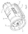
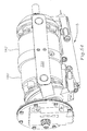
- FIG. 6-15 A preferred embodiment of the transmission shown schematically in Fig. 1 is shown in Figs. 6-15 as a serial, bent axis, double planetary, hydromechanical, continuously variable transmission.
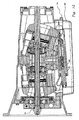
- This transmission has a housing 120, shown in Figs. 6, and 10-20, for enclosing an operating assembly, shown in Figs. 7-13.
- the housing 120 has an input end 119 from which protrudes the outer end 64 of the input shaft 65, and an input end peripheral flange 123 by which the transmission can be attached to the vehicle engine 40.
- the housing 120 also has an output end 121 from which protrudes the output end 96 of the output shaft 76.
- the housing 120 has a large opening 122 at the underside surrounded by a peripheral flange 124 to which a sump pan 125, shown in Figs. 6, 11-14 and 21-24, is attached by conventional removable fasteners (not shown) for easy access to the interior of the housing 120.
- a circular end closure 126 shown in Figs. 6 and 10-13, and shown in detail in Figs. 25-31, is fastened into a circular recess 127 in the input end opening of the housing 120 by machine screws 128. Holes 129 around the outside of the end closure 126 receive the screws 128 which are threaded into tapped holes in bosses 130 in the inside of the housing 120 spaced around the circular recess 127.
- the circular end closure 126 has a central opening 131 through which the end of the input shaft 65 extends, and a central cylindrical recess 132 for receiving the make-up pump 75.
- the make-up pump 75 can be any suitable type of pump for the application, such as a vane pump of known construction, having a pump rotor driven by the input shaft 65 in a pump housing 133, shown in Figs. 10-13 and Figs. 32-36.
- the brake 85 enables the pump 60 and downstream components of the operating assembly to be smoothly engaged and disengaged from the input shaft 65, as described above and in detail below.
- the operating assembly shown in Figs. 7-13 includes the input hydrostatic pump unit 50 and the output hydrostatic motor unit 60 hydraulically related to each other through the fluid passages 90 and 95, which extend straight through a stationary manifold block 140 between the pump 50 and the motor 60.
- the pump 50 and motor 60 are mechanically related through the first variable ration gear set such as an epicyclic planetary or differential gear set 70 and the second similar gear set 80.
- the stationary manifold block 140 shown in Figs. 7-15 and shown in detail in Figs. 37-42, is connected to the housing 120 through a pair of identical connector links 145, as shown in Figs. 10, 14 and 48.
- Each connector link 145 has a longitudinal stiffening rib 146 along its outside face, primarily to resist loads exerted on the link 145 by the yokes, discussed below.
- the links 145 are fastened by screws 148 into recesses 149, one in each side of the stationary manifold block 140, and project out through manifold 140 in the housing without unnecessary enlargement of the housing 120.
- an input yoke 151 and an output yoke 152 are each pivotally connected to the connector links 145 by swivel barrels 154 and 156 on the ends of yoke arms 158 and 160 on the input and output yokes 151 and 152.
- Both yokes 151 and 152 are identical to each other, so the description of one will suffice for both.
- the swivel barrels 154 and 156 are mounted for swiveling about two horizontal axes 170 and 172, shown in Fig. 10, on longitudinally spaced integral stub shafts 162 and 164 that project inwardly from the connector links 145.
- the two sets of stub shafts 162 and 164 are aligned on the axes 170 and 172, shown in Fig. 10, that intersect the main longitudinal axis 174 of the machine at the center of curvature of two convex spherical bearings 176 and 178 on which annular pump and motor cylinder blocks 180 and 182 are guided, as described below.
- the main longitudinal axis 174 of the machine coincides with the axis of the input shaft 65 and the coaxial output shaft 76.
- Each yoke 151 and 152 has a mounting flat 183 on its lower surface to which is attached a control clevis 184 and 186, respectively, each having a pair of spaced-apart depending arms.
- Control links 188 and 190 seen in Figs. 7- 9, are pinned between the lower ends of the control clevis arms and a control actuator 192, shown in detail in Figs. 8, 9, 11-13 and 49.
- the actuator 192 includes an actuator cylinder block 189, shown in detail in Figs. 50-53, which is fastened to the underside of the stationary manifold block 140, as shown in Figs. 8 and 9, so it is stationary relative to the manifold block 149 and the housing 120.
- the control links 188 and 190 are pinned to the ends of bars 191 and 193 mounted on the outer ends of two control pistons 194 and 196 and held thereon by nuts 197.
- the control pistons move in the cylinder 195 in the cylinder block 189 under the influence of hydraulic fluid controlled by a spool 198 connected to a rod 199 moved by the servomotor or stepper motor 110 to control the tilt angle of the yokes 151 and 152, as discussed below.
- the stationary nature of the actuator 192 makes control of the control yokes 151 and 152 simple, consistent and reliable.
- the stationary nature of the stationary manifold block 140 also affords access into the fluid circuit for simple and 152 simple, consistent and reliable.
- the stationary nature of the stationary manifold block 140 also affords access into the fluid circuit for simple connection of make-up fluid flow lines by way of a tapped port 201. External taps into the pressure channels for regenerative braking/acceleration and hydraulic power take-off are also made possible without the use of rotating interfaces or the like by the stationary manifold block 140.
- the make-up pump housing 133 shown in Figs. 32-36, has a cylindrical recess 202 in which a rotor 204 and vanes 205 of the make-up pump 75 are mounted and driven by the input shaft 65, as shown in Figs. 10-13, for pressurizing fluid drawn from the sump pan 125 to recharge the fluid circuit with fluid lost through leakage, and to pressurize the actuator 92.
- the hydraulic fluid from the make-up pump also is use to lubricate the bearings and sliding interfaces in the transmission.
- the annular pump and motor cylinder blocks 180 and 182 of the input and output hydrostatic units 50 and 60 each include a ring of cylinders 206 and 208 in which hollow pump and motor pistons 210 and 212, respectively, are disposed, as shown in Figs 11-13. All the pistons 210 and 212 are identical, so a description of one will suffice for all.
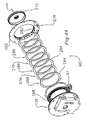
- Each piston as best seen in Fig. 46, has a spherical head 214 and a cylindrical base 216 connected by a cylindrical shank 215. The cylindrical base 216 tapers toward the head 214 from a pair of annular grooves 218 and 220 in the base for receiving piston rings (not shown).
- An axial bore 222 extends completely through each piston 210 and 212 for conveying fluid from the cylinders in the cylinder block on one side of the manifold block, through the fluid passages 90 and 95 in the manifold block, through the pistons on the other side of the manifold block and into the cylinders in the other cylinder block.
- the spherical heads of the pistons 210 and 212 are seated in spherical sockets 224 in a pump torque ring 226 and a motor torque ring 228, each having a flat face in contact with the manifold block 140.
- the only two rotating fluid transfer interfaces in the transmission are the interfaces between the two sides of the manifold block 140 and the two torque rings 226 and 228. No torque is transmitted through these interfaces so distortion under torque load is minimal, thereby reducing leakage which otherwise could be caused by distortion of the torque ring face under load.
- the torque rings 226 and 228 are supported for rotation on a ring of caged needle bearings 230 surrounding a bearing support annulus 232 fastened to the center of the manifold block 140 by screws 234, one on each side of the manifold block.
- the piston heads 214 are held in the sockets 224 of the torque rings 226 and 228 by retainer rings 238 which are integral with the ring gears 84 and 74.
- the retainer rings 238 are fastened to the torque rings 226 and 228 by fasteners 240 which also provide a torque path between the ring gears 84 and 74 and the torque rings 226 and 228.
- the outer ends of the cylinders 206 and 208 are closed by floating pucks 236 best seen in Fig. 46.
- the pucks 236 each have a seal groove 237 for receiving a seal ring (not shown) and a spring groove 239 for receiving an annular wave spring which biases the puck outward against flat annular bearing surfaces 242 and 244 on the inner faces of the yokes 151 and 152, as shown in Fig. 47 for the yoke 152.
- the floating puck can move slightly axially and tilt slightly to follow a momentary perturbation or deviation from flatness of the yoke inner bearing surfaces 242 and 244.
- each puck 236 provides a hydrostatic bearing which just reacts the fluid force inside the cylinders 206 and 208 to minimize wear of the pucks and the bearing surfaces 242 and 244 of the yokes 151 and 152.
- An axial biasing force is exerted to urge the cylinder blocks 180 and 182 against That axial force is exerted by a set of wave springs 246 compressed between a snap ring (not shown) fitted into grooves 247 in the fluted axial bore 209 of the pump and motor cylinder blocks 180 and 182, and against a spherical ring 248 and 250 which is guided for tilting on the spherical bearings 176 and 178 about the centers of curvature of the spherical interfaces of the spherical rings and spherical bearings.
- the spherical rings 248 and 250 guide the pump and motor cylinder blocks 180 and 182 on the spherical bearings 176 and 178 for rotation and tilting about their respective centers of mass.
- Those centers of curvature coincide with the intersection of the axes 170 and 172 through the stub shafts 162 and 164, and the longitudinal axis 174 of the machine, as shown in Fig. 10, so that the axes of rotation of the cylinder blocks always intersects the tilting axis of the yokes 151 and 152 and the cylinder blocks always rotate about their centers of mass to ensure dynamic balance of the rotating elements.
- the axial force exerted by the two sets of wave springs 246 is transmitted through the spherical rings 248 and 250 to the spherical bearings 176 and 178, and thence (on the pump side) to a pump preload flange 252, shown most clearly in Figs. 46 and 46A.
- the radial outer surface of the pump preload flange 252 is splined at 253 and engaged with splines 254 in the bore of the ring gear 84.
- the splines 254 are shallower than the teeth of the ring gear 84, so the preload flange 252 can slide into the ring gear 84 only about one quarter of the way until it is engaged by the higher teeth of the ring gear 84.
- This engagement enables the axial force exerted on the preload flange 252 by the spherical bearing 176 to be transmitted to the ring gear 84 and its integral retainer ring 238 and thence to the torque ring 226 for ensuring contact of the torque ring 226 against the manifold block during start-up so that the fluid system remains sealed and make-up pump pressure can be developed by the make-up pump 75 for lubrication flow and charging the system during start-up.
- a stator tube 260 for coupling the pump planet carrier 77 to the brake 85 includes an externally splined inner end 262 engaged with an internally splined tubular extension 264 on the pump planet carrier 77.
- the stator tube 260 surrounds the input shaft 65 and extends from the planet carrier 77 to an outer splined end 266 engaged with an internally splined ferrule 268 projecting inwardly from a brake flange 270.
- the brake flange 270 has an outer peripheral cylindrical flange 272 that is castellated or toothed on its outer radially facing surface to receive inwardly projecting radial teeth 274 of three clutch discs 276.
- the brake flange 270 and the clutch discs 276 lie concentrically within a brake ring 278 having an outer radial flange 280 that is fastened to the circular end closure 126 and has an axial cylindrical section 282 concentrically surrounding the cylindrical flange 272.
- the interior of the axial cylindrical section 282 is grooved or slotted to receive teeth 284 projecting radially outward from the outer end of a plurality of annular clutch plates 286 bracketing the clutch discs 276.
- a radial lip at the end of the axial cylindrical section 282 prevents the clutch discs 276 and plates 286 from being pushed out of the end of the axial cylindrical section 282.
- An annular brake piston 288 is seated in the annular cylinder 134 and is movable axially under influence of fluid admitted in the annular cylinder 134 behind the brake piston 288 to exert a precisely controlled axial force on the clutch plates 286 and the clutch discs 276 to transmit torque from the brake flange 270 to the brake ring 278 and thence to the housing.
- the fluid pressure released into the annular cylinder 134 for acting against the brake piston 288 is controlled by the brake modulation valve 97, which is a commercially available pulse modulated solenoid controlled fluid valve. In this way, the reaction torque transmitted from the pump planet carrier to ground, and hence the torque transmitted to the pump 50, is precisely controlled by the controller 100 through the brake modulation valve 97.
- the brake 85 In operation, when the starter of the vehicle engine is energized, the brake 85 is released to allow the planet carrier 77 to spin freely, preventing torque from being transmitted to the pump.
- the starter motor has a much lighter load without having to rotate the pump and there is no chance that the vehicle could surge forward or backward because of an inadvertent adjustment of the pump displacement.
- the rotating input shaft 65 rotates the make-up pump 75 and fluid pressure at make-up pressure is developed in the system.
- Pressurized fluid flows from the make-up pump 75 through a radial hole 280 in the input shaft 65 and through an axial hole 282 and then out through another radial hole 284 into an annular space 286 between the input shaft 65 and the stator tube 260.
- the fluid flows along the annular space 286 and lubricates a needle bearing between the planet carrier 77 and the sun gear 83, shown in Fig. 46.
- the fluid continues flowing along the annular space 286 and squirts up through a hole 290 to be deflected by an oil deflector 292 into an axial hole in a pinion shaft 294 on which the pump planet gears 82 are mounted for rotation on needle bearings 296.
- Those needle bearings 296 are lubricated by hydraulic fluid flowing from the axial holes and out radial holes in the pinion shaft 294.
- the motor planet gears are likewise lubricated by fluid flowing through radial and axial holes in the end of the input shaft 65 and into similar fluid flow passages in and around the bearings and gears inside the motor 60 as illustrated in Figs. 10-13.
- the control unit 100 sends a signal to the servomotor or stepper motor 110, mounted on a bracket 298 to move the control rod 199 and the spool valve 198 threaded onto the rod 199 to a zero displacement position from which forward or reverse acceleration can be commenced.
- the driver selects forward or reverse on the drive selector switch 118 and depresses the accelerator.
- the controller 100 senses the rate and extent of depression of the accelerator and adjusts the transmission accordingly by sending a signal to the stepper motor 110 to move the control rod and spool valve to a new position at the desire speed, while also adjusting the throttle to increase the engine speed to some designated speed of operation, preferably at a rate of increase and to an operating speed that will result in optimal efficiency and minimal emissions.
- the position of the spool valve 198 controls the position of a follower spool sleeve 200 which in turn controls the position of the pump control piston 194, using system pressure delivered to a larger cross-sectional area behind the step 299 in the piston 194. Both pump control piston and motor control piston 196 are biased toward the left in Figs.
- the control rod 199 is pulled further to the right in Figs. 11-13 and 49 to cause the pump control piston 194 to move to the right correspondingly.
- the pump control piston will engage the end of the motor control piston 196 and the two control pistons 194 and 196 will move together toward the right through the continuously varying transmission ratio to the final ratio at hydraulic lock-up at which the motor is at zero displacement and the pump is at some large displacement.
- the advantage of the swashplate design is that the housing can be made smaller because the excursion of the tilting swashplates is less that the corresponding excursion of the tilting yokes 151 and 152 and their cylinder blocks.
- the disadvantage of the swashplate design is that it tends to wear faster because of the lateral forces exerted by the pistons in the cylinders. The resulting frictional forces also result in somewhat higher internal losses, so swashplate hydrostatic units have a bit lower efficiency that the bent axis units used in the embodiment of Figs. 6-15.
Landscapes
- Engineering & Computer Science (AREA)
- General Engineering & Computer Science (AREA)
- Mechanical Engineering (AREA)
- Control Of Fluid Gearings (AREA)
- Electrical Discharge Machining, Electrochemical Machining, And Combined Machining (AREA)
- Control Of Transmission Device (AREA)
Claims (16)
- Transmission variable de manière continue comprenant :deux unités hydrauliques comportant une pompe (50) et un moteur (60), ayant chacune un élément rotatif (180, 182) et un élément de réaction mis à la terre (151, 152), au moins une parmi lesdites utilisées hydrauliques (50) étant à cylindrée variable ;un système de commande (100) destiné à commander ladite une unité hydraulique parmi les unités hydrauliques;un train d'engrenage (70) de moteur à démultiplication variable ayant des premier, deuxième et troisième éléments (72, 74, 73) de roues engrenées, et un train d'engrenages (80) de pompe à démultiplication variable ayant des premier, deuxième et troisième éléments (82, 84, 83) de roues engrenées ;un arbre d'entrée (65) raccordé audit premier élément (72) de roue dudit train d'engrenages (70) de moteur ;un arbre de sortie (76) raccordé audit deuxième élément (74) de roue dudit train d'engrenages de moteur et audit élément rotatif (182) de ladite seconde unité hydraulique (60) ;ledit troisième élément (73) de roue dudit train d'engrenages (70) de moteur étant raccordé audit troisième élément (83) de roue dudit train d'engrenages (80) de pompe ;ledit deuxième élément de roue dudit train d'engrenages de pompe étant raccordé audit élément rotatif de ladite première unité hydraulique ;lesdites deux unités hydrauliques étant raccordées de manière hydraulique de telle manière que le fluide refoulé depuis la première unité hydraulique s'écoule vers la seconde unité hydraulique et inversement ;caractérisé par un frein (85) raccordant de manière détachable ledit premier élément (82) dudit train d'engrenages (80) de pompe à la terre ;
moyennant quoi, un couple d'entrée appliqué audit arbre d'entrée (65) est transmis au travers de celui-ci à ladite pompe (50), lorsque ledit frein (85) est mis en prise, au moyen desdits premier et troisième éléments (72, 73) dudit train d'engrenages (70) de moteur à démultiplication variable et de là, au moyen desdits troisième, premier et deuxième éléments (82, 84, 83) dudit train d'engrenages (80) de pompe à démultiplication variable, réagissant au travers dudit frein (85) mis en prise avec la terre, pour mettre en rotation ladite pompe (50) et mettre sous pression un fluide de travail dans ladite pompe ; ledit transfert dudit couple d'entrée depuis ledit arbre d'entrée (65) vers ladite pompe (50) créant un couple de réaction qui est transféré au travers dudit deuxième élément (74) dudit train d'engrenages (70) de moteur à démultiplication variable audit arbre de sortie (76), ledit fluide mis sous pression étant acheminé au travers d'une ouverture dans un bloc collecteur (140) entre lesdites unités hydrauliques vers ledit moteur (60) et excitant ledit moteur (60) pour produire un couple de moteur qui est transféré audit arbre de sortie (76) en plus dudit couple de réaction en tant que couple de sortie dans ledit arbre de sortie (76). - Transmission variable de manière continue selon la revendication 1, dans laquelle :lesdites unités hydrauliques (50, 60) et lesdits deux trains d'engrenages (70, 80) variables sont configurés pour engendrer un rapport final, et pour diviser ledit couple d'entrée dans des première et seconde voies parallèles, ladite première voie parallèle étant une voie mécanique directe vers l'arbre de sortie (76), et la seconde voie parallèle traversant lesdites première et seconde unités hydrauliques (50, 60) ;ladite seconde unité hydraulique (60) et ladite première unité hydraulique (50) ayant un rapport de cylindrées qui multiplie un couple au travers de ladite seconde voie parallèle, ajoutant de ce fait au couple transmis au travers de ladite première voie parallèle ;moyennant quoi, un ajustement de ladite cylindrée de moteur sur zéro réduit une multiplication de couple en provenance des unités hydrauliques (50, 60) à zéro de sorte qu'elles agissent uniquement pour réagir à un couple provenant du couple mécanique de ladite première voie parallèle et de sorte que ledit couple d'entrée et une énergie passent tous directement au travers dudit train d'engrenages (70) de moteur vers ledit arbre de sortie (76), et une stimulation dudit moteur (60) jusqu'à la cylindrée maximale et de ladite pompe (50) jusqu'à une cylindrée nulle place ladite transmission dans un réglage de "maintien de point mort" destiné à maintenir un véhicule dans une position stationnaire, dans laquelle ledit moteur (60) et ainsi, ledit arbre de sortie (76), ne peut être mis en rotation dans une quelconque direction car ladite pompe (50) ne peut accepter un quelconque fluide expulsé dudit moteur (60).
- Transmission variable de manière continue selon la revendication 2, dans laquelle :une stimulation de la pompe à cylindrée variable (50) dans l'une ou l'autre direction depuis ladite position de cylindrée nulle de celle-ci change une direction d'écoulement de fluide depuis ladite pompe (50) vers ledit moteur (60) et entraîne ledit moteur (60) et ainsi, ledit arbre de sortie (76) dans l'une ou l'autre parmi la direction vers l'avant ou vers l'arrière ;moyennant quoi ladite transmission multiplie de manière hydraulique un couple à la fois vers l'avant et vers l'arrière, sans avoir à changer une quelconque transmission par engrenage, de la manière suivante :où A = 1/(1+(Rm/Sm))xRp/Sp x cylindrée du moteur/cylindrée de la pompe).


- Transmission variable de manière continue selon la revendication 1, comprenant en outre :un appareil de commande (105, 100) destiné à stimuler ledit moteur (60) jusqu'à une cylindrée nulle et relâcher ledit frein (85) pour déconnecter ledit premier élément (82) dudit train d'engrenages (80) de pompe de la terre ;moyennant quoi ledit relâchement dudit frein (85) permet audit arbre de sortie d'être mis en rotation librement dans l'une ou l'autre direction, quelle que soit une cylindrée de pompe ou une vitesse d'entrée, et ledit arbre de sortie et les applications de puissance entraînées de ce fait sont déconnectées d'un moteur primaire.
- Transmission variable de manière continue selon la revendication 1, dans laquelle :ledit premier élément (82) dudit train d'engrenages (80) de pompe est raccordé à la terre au moyen dudit frein pouvant être relâché (85) et peut être relâché pour dégager un moteur primaire de la transmission lorsqu'on le souhaite ;moyennant quoi un dégagement dudit frein (85) au démarrage permet de disposer d'un temps pour un appoint en pression et à une lubrification d'atteindre les unités hydromécaniques (50, 60) avant que leur mise en rotation ne démarre, et une mise en prise progressive dudit frein (85) au cours d'un démarrage, et entraînement, facilite des caractéristiques de décollage.
- Transmission variable de manière continue selon la revendication 1, dans laquelle :lesdites unités hydrauliques de pompe (50) et de moteur (60) sont toutes deux des unités à accès brisé à cylindrée variable, raccordées de manière hydraulique en série au travers dudit bloc collecteur (140) stationnaire, au travers duquel un fluide hydraulique passe de ladite pompe (50) audit moteur (60) et inversement ;ladite pompe (50) disposant de cylindre (206) de pompe contenant des pistons (210) de pompe munis de têtes (214) de pompe fixées dans une couronne de couple (226) de pompe en contact au travers d'une interface hydraulique avec un côté dudit bloc colleteur (140) stationnaire, lesdits pistons (210) ayant des alésages axiaux (222) au travers desquels ledit fluide mis sous pression dans ladite pompe (50) passe de ladite pompe (50) et de là, au travers dudit bloc collecteur (140) ;ledit moteur (60) disposant de cylindres (208) de moteur contenant des pistons (212) de moteur munis de têtes (214) de piston de moteur fixées dans une couronne de couple (228) de moteur en contact avec un côté dudit bloc collecteur (140) en opposition audit un côté au travers d'une interface hydraulique, ledit piston (212) de moteur ayant des alésages axiaux (222) au travers desquels un fluide mis sous pression dans ladite pompe (50) passe dudit bloc collecteur (140) dans des cylindres (208) dudit moteur (60) pour exciter ledit moteur (60) et convertir une énergie dudit fluide mis sous pression en un couple.
- Transmission variable de manière continue selon la revendication 6, comprenant en outre :un palier à rotule (176, 178) dans chacune parmi lesdites unités hydrauliques, chaque palier à rotule (176, 178) ayant un centre de courbure se trouvant sur un axe de pivotement d'un tube (154, 156) en fourche grâce auquel une fourche (151, 152) est raccordée de manière pivotante de chaque côté dudit bloc collecteur (140) pour supporter lesdits éléments rotatifs (180, 182) desdites unités hydrauliques ;lesdits éléments rotatifs des deux dites unités hydrauliques (50, 60) comportent des blocs-cylindres (180, 182) qui sont guidés sur des extrémités axiales de ceux-ci par lesdits paliers à rotule (176, 178) ;des ressorts (246) sollicités entre lesdits paliers à rotule (176, 178) et lesdits blocs cylindres pour précharger lesdits blocs-cylindres (180, 182) contre lesdites fourches (151, 152) et pour précharger lesdites couronnes de couple (226, 228) contre ledit bloc collecteur (140) stationnaire ;moyennant quoi ledit préchargement par ressort fournit un joint hydraulique initial au niveau desdites interfaces hydrauliques.
- Transmission variable de manière continue selon la revendication 6, dans laquelle :lesdits pistons creux (210) comportent chacun une tête sphérique (214) au niveau d'une extrémité, ladite tête sphérique (214) étant fixée à ladite couronne de couple (226) de pompe pour une articulation relativement à celle-ci au cours d'une mise en fonctionnement de ladite pompe (50) ;moyennant quoi ledit piston (210) est libre en termes qu'articulation lorsque lesdits cylindres (206) sont mis en rotation tout en maintenant une longueur suffisante de mise en prise et d'étanchéité hydraulique dans ledit alésage de cylindre, et lesdits pistons creux (210) font passer un écoulement de fluide depuis lesdits cylindres (206) jusqu'au dit collecteur stationnaire (140) et inversement, exempt de limitation sensible, en réduisant également le poids du piston (210) et en réduisant de ce fait un frottement du piston dû à un chargement centrifuge.
- Transmission variable de manière continue selon la revendication 1, dans laquelle :lesdites unités hydrauliques de pompe (50) et de moteur (60) sont des unités à axes brisés à cylindrée variable ayant des éléments rotatifs étant mis en rotation autour de leur propre centre de masse ;moyennant quoi lesdits éléments rotatifs sont équilibrés par nature et peuvent être mis en rotation avec une vitesse de rotation élevée et donc à des niveaux de puissance élevés.
- Transmission variable de manière continue selon la revendication 1, dans laquelle :les deux parmi les unités hydrauliques (50, 60) sont des unités à cylindrée variable, ayant chacune des blocs-cylindres (180, 181) supportés par des fourches (151, 152) qui sont reliés entre elles ;moyennant quoi toute charge de séparation interne est résolue de manière interne au travers desdites fourches et de la structure de liaison.
- Transmission variable de manière continue selon la revendication 10, comprenant en outre :des plaquettes d'équilibre (236) entre lesdits blocs-cylindres (180, 181) et lesdites fourches (151, 152) et ayant des paliers hydrostatiques au niveau d'une interface entre lesdites plaquettes (236) et lesdites fourches (151, 152) pour supporter lesdits blocs-cylindres (180, 181) des deux unités hydrauliques (50, 60) sur lesdites fourches (151, 152) ; etlesdites plaquettes d'équilibre (236) étant déplaçable axialement relativement auxdits blocs-cylindres (180, 181) pour s'adapter à un certain fléchissement desdites fourches (180, 181) ;moyennant quoi lesdites plaquettes d'équilibre (236) se déplacent axialement en cas de fléchissement de fourche alors que lesdites plaquettes d'équilibre (236) restent sensiblement plates contre lesdites fourches (180, 181) pour maintenir l'intégrité dudit palier hydrostatique.
- Transmission variable de manière continue selon la revendication 1, dans laquelle ledit système de commande (100) comprend :un piston de commande (196) de moteur pouvant être déplacé dans un cylindre de commande (195) entre des positions correspondantes à une cylindrée nulle et une cylindrée maximale dudit moteur (60) ;un piston de commande (194) de pompe pouvant être déplacé dans un cylindre de commande (195) de pompe entre des positions correspondant à la cylindrée maximale vers l'arrière, au travers d'une cylindrée nulle, et une cylindrée maximale vers l'avant, ledit piston de commande (194) de pompe ayant une face arrière disposée selon une orientation de mise en prise de fluide dans ledit cylindre de commande (195) de pompe ;des liaisons de commande (190) entre ledit piston de commande (196) de moteur et ladite fourche (152) de moteur destinée à commander la cylindrée dudit moteur (60) en commandant ladite position dudit piston de commande (196) de moteur, et des liaisons de commande (188) entre ledit piston de commande (194) de pompe et ladite fourche (151) de pompe destinée à commander la cylindrée de ladite pompe (50) en commandant ladite position dudit piston (194) de commande de pompe ;une force de sollicitation de piston de moteur agissant sur ledit piston de commande (196) de moteur pour solliciter ladite fourche (152) de moteur vers une position d'inclinaison maximale de celle-ci, dans laquelle ladite cylindrée de moteur est à un niveau maximum ;une force de sollicitation de piston de pompe agissant sur ledit piston de commande (194) de pompe pour solliciter ladite fourche (151) de pompe vers ladite cylindrée maximale de ladite pompe vers l'arrière ;une vanne modulatrice (115) au travers de laquelle une pression du système est recueillie depuis ledit bloc collecteur (140) et est délivrée au travers de ladite face arrière dudit piston de commande (194) de pompe pour commander ladite position de piston de pompe ;moyennant quoi une pression du système admise par ladite vanne modulatrice (115) dans ledit cylindre de commande (195) de pompe et agissant sur ladite face arrière dudit piston de commande (194) de pompe génère une force de pression qui surmonte ladite force de sollicitation de piston de pompe et ladite force de sollicitation de piston de moteur pour amener ladite pompe à effectuer une course vers ladite cylindrée maximale de celle-ci dans la direction vers l'avant jusqu'à une position déterminée par ladite vanne modulatrice (115).
- Transmission variable de manière continue selon la revendication 12, dans laquelle :ladite force de sollicitation de piston de moteur et ladite force de sollicitation de piston de pompe sont des forces hydrauliques exercées par transmission de fluide à un niveau de pression du système admises dans ledit cylindre de commande (195) de pompe et ledit cylindre de commande (195) de moteur et appliquées contre des faces avant desdits pistons de commande (194, 196) de pompe et de moteur.
- Transmission variable de manière continue selon la revendication 12, dans laquelle :ladite force de sollicitation est exercée par une pression du système délivré auxdites faces de piston par le biais de passages internes dans ledit bloc collecteur (140) pour acheminer une pression du système vers ladite surface arrière dudit piston de commande (196) de moteur pour mettre sous pression ledit cylindre de commande (195) de moteur et exercer une force de pression contre ladite face arrière dudit piston de commande (196) de moteur avec une pression du système, ladite pression du système agissant sur ladite zone arrière de piston de commande du moteur pour solliciter ladite fourche (152) de moteur vers une position d'inclinaison maximale de celle-ci, dans laquelle ladite cylindrée de moteur est à un niveau maximum ;des passages de fluide depuis ladite vanne modulatrice (115) vers ledit cylindre de commande (195) de pompe pour acheminer une pression du système jusqu'à une surface annulaire dudit piston de commande (194) de pompe, qui est égale, en termes de surface à ladite surface de face arrière dudit piston de commande (196) de moteur pour solliciter ledit piston de commande (194) de pompe vers ladite cylindrée maximale de ladite pompe vers l'arrière.
- Transmission variable de manière continue selon la revendication 1, comprenant en outre :une pompe d'appoint (75) raccordée audit arbre d'entrée (65) et logée dans une plaque d'obturation (126) de logement stationnaire, ladite pompe d'appoint (75) délivrant un fluide à basse pression auxdites unités hydrauliques (50, 60) pour effectuer un réapprovisionnement par suite d'une perte de fluide par fuite du circuit de fluide ainsi que pour fournir un écoulement de fluide au travers d'un circuit de lubrification/refroidissement et fournir une pression de fluide pour ledit frein (85).
- Transmission variable de manière continue selon la revendication 1, comprenant en outre :des prises stationnaires dans ledit bloc collecteur (140) stationnaire pour recueillir une pression du système provenant dudit bloc collecteur (140) au travers d'un raccordement de fluide stationnaire.
Applications Claiming Priority (3)
| Application Number | Priority Date | Filing Date | Title |
|---|---|---|---|
| US6537797P | 1997-11-12 | 1997-11-12 | |
| US65377P | 1997-11-12 | ||
| PCT/US1998/024053 WO1999024738A1 (fr) | 1997-11-12 | 1998-11-12 | Machine hydraulique |
Publications (3)
| Publication Number | Publication Date |
|---|---|
| EP1029183A1 EP1029183A1 (fr) | 2000-08-23 |
| EP1029183A4 EP1029183A4 (fr) | 2005-12-07 |
| EP1029183B1 true EP1029183B1 (fr) | 2008-01-02 |
Family
ID=22062301
Family Applications (1)
| Application Number | Title | Priority Date | Filing Date |
|---|---|---|---|
| EP98957830A Expired - Lifetime EP1029183B1 (fr) | 1997-11-12 | 1998-11-12 | Machine hydraulique |
Country Status (7)
| Country | Link |
|---|---|
| US (1) | US6358174B1 (fr) |
| EP (1) | EP1029183B1 (fr) |
| JP (1) | JP2001522974A (fr) |
| AT (1) | ATE382811T1 (fr) |
| AU (1) | AU1399399A (fr) |
| DE (1) | DE69838954D1 (fr) |
| WO (1) | WO1999024738A1 (fr) |
Cited By (1)
| Publication number | Priority date | Publication date | Assignee | Title |
|---|---|---|---|---|
| DE102012213170A1 (de) * | 2012-07-26 | 2014-01-30 | Zf Friedrichshafen Ag | Vorrichtung zum Variieren der Volumina einer ersten Hydraulikmaschine und einer zweiten Hydraulikmaschine |
Families Citing this family (88)
| Publication number | Priority date | Publication date | Assignee | Title |
|---|---|---|---|---|
| US7374005B2 (en) * | 2000-01-10 | 2008-05-20 | The United States Of America As Represented By The Administrator Of The U.S. Environmental Protection Agency | Opposing pump/motors |
| US7337869B2 (en) * | 2000-01-10 | 2008-03-04 | The United States Of America As Represented By The Administrator Of The United States Environmental Protection Agency | Hydraulic hybrid vehicle with integrated hydraulic drive module and four-wheel-drive, and method of operation thereof |
| US6719080B1 (en) | 2000-01-10 | 2004-04-13 | The United States Of America As Represented By The Administrator Of The Environmental Protection Agency | Hydraulic hybrid vehicle |
| US8177009B2 (en) | 2000-01-10 | 2012-05-15 | The United States Of America As Represented By The Administrator Of The U.S. Environmental Protection Agency | Independent displacement opposing pump/motors and method of operation |
| US8166584B2 (en) | 2000-06-13 | 2012-05-01 | Wcm Industries, Inc. | Overflow assembly for bathtubs and the like |
| US20020094902A1 (en) | 2001-01-18 | 2002-07-18 | Pollman Frederic W. | Small vehicle transmission |
| US6904997B2 (en) * | 2001-05-31 | 2005-06-14 | Sauer-Danfoss, Inc. | Compact vehicle transmission |
| CA2363653A1 (fr) * | 2001-11-22 | 2003-05-22 | Gerald Dyck | Boite de transmission hydro-mecanique variable de facon continue |
| US7743115B2 (en) * | 2002-02-27 | 2010-06-22 | Motorola, Inc. | Software content downloading methods in radio communication networks |
| AU2003240571A1 (en) * | 2002-05-20 | 2004-01-23 | Folsom Technologies, Inc. | Hydraulic torque vectoring differential |
| US6663525B1 (en) * | 2002-07-17 | 2003-12-16 | Case Corporation | Hydro-mechanical transmission with automatic braking capability and method of operation |
| DE20217308U1 (de) * | 2002-11-09 | 2003-03-06 | perma-tec GmbH & Co. KG, 97717 Euerdorf | Vorrichtung zur Versorgung mehrerer Schmierstellen an Maschinenteilen mit Schmierstoff |
| US7011600B2 (en) | 2003-02-28 | 2006-03-14 | Fallbrook Technologies Inc. | Continuously variable transmission |
| US6945041B2 (en) * | 2003-06-27 | 2005-09-20 | Sauer-Danfoss, Inc. | Bent axis hydrostatic module with multiple yokes |
| US6996980B2 (en) | 2003-06-27 | 2006-02-14 | Sauer-Danfoss Inc. | Bent axis hydrostatic unit with multiple yokes |
| US7500687B2 (en) * | 2004-01-31 | 2009-03-10 | Lockheed Martin Corporation | Vehicle suspension systems |
| KR101276082B1 (ko) | 2004-10-05 | 2013-06-18 | 폴브룩 테크놀로지즈 인크 | 연속 가변 변속기 |
| EP1705372A1 (fr) * | 2005-03-11 | 2006-09-27 | Innas B.V. | Pompe variable ou moteur hydraulique |
| JP2007089275A (ja) * | 2005-09-21 | 2007-04-05 | Smc Corp | 電動シリンダ |
| KR101831828B1 (ko) | 2005-10-28 | 2018-02-23 | 폴브룩 인텔렉츄얼 프로퍼티 컴퍼니 엘엘씨 | 전동 드라이브 |
| EP1954959B1 (fr) | 2005-11-22 | 2013-05-15 | Fallbrook Intellectual Property Company LLC | Transmission à variation continue |
| US7536856B2 (en) * | 2005-11-30 | 2009-05-26 | Caterpillar Inc. | System for controlling a power output |
| CA2976893C (fr) | 2005-12-09 | 2019-03-12 | Fallbrook Intellectual Property Company Llc | Transmission a variation continue |
| DE102006010508A1 (de) * | 2005-12-20 | 2007-08-09 | Robert Bosch Gmbh | Fahrzeug mit einem Antriebsmotor zum Antreiben eines Fahrantriebs und einer Arbeitshydraulik |
| EP1811202A1 (fr) | 2005-12-30 | 2007-07-25 | Fallbrook Technologies, Inc. | Transmission à variation continue |
| US7953526B2 (en) * | 2006-01-18 | 2011-05-31 | I-Guide Robotics, Inc. | Robotic vehicle controller |
| US8239083B2 (en) * | 2006-01-18 | 2012-08-07 | I-Guide Robotics, Inc. | Robotic vehicle controller |
| US7444809B2 (en) * | 2006-01-30 | 2008-11-04 | Caterpillar Inc. | Hydraulic regeneration system |
| US7588509B1 (en) | 2006-03-14 | 2009-09-15 | John David Marsha | Infinitely variable gear transmission with parallel hydraulic ratio control |
| US7393065B2 (en) * | 2006-06-01 | 2008-07-01 | Lockheed Martin Corporation | Redundant braking system |
| CN102278200B (zh) | 2006-06-26 | 2014-05-14 | 福博科知识产权有限责任公司 | 无级变速器 |
| US20080066613A1 (en) * | 2006-09-15 | 2008-03-20 | Lockheed Martin Corporation | Perforated hull for vehicle blast shield |
| US20080173167A1 (en) | 2006-09-15 | 2008-07-24 | Armor Holdings | Vehicular based mine blast energy mitigation structure |
| WO2008045368A2 (fr) * | 2006-10-05 | 2008-04-17 | Folsom Technologies International Llc | Transmission boîte-pont à variation continue hydromécanique |
| US7431124B2 (en) | 2006-10-06 | 2008-10-07 | White Drive Products, Inc. | Hydraulic transmission assembly |
| EP2125469A2 (fr) * | 2007-02-01 | 2009-12-02 | Fallbrook Technologies Inc. | Système et procédés pour la commande d'une transmission et/ou d'un premier moteur d'entraînement |
| CN104121345B (zh) | 2007-02-12 | 2017-01-11 | 福博科知识产权有限责任公司 | 无级变速器及其方法 |
| EP2700843A3 (fr) | 2007-02-16 | 2017-11-08 | Fallbrook Intellectual Property Company LLC | Transmissions infiniment variables, transmissions variables en continu, procédés, ensembles, sous-ensembles, et composants de celles-ci |
| CN102943855B (zh) | 2007-04-24 | 2016-01-27 | 福博科技术公司 | 电力牵引传动装置 |
| WO2008154437A1 (fr) | 2007-06-11 | 2008-12-18 | Fallbrook Technologies Inc. | Transmission à variation continue |
| US7634911B2 (en) * | 2007-06-29 | 2009-12-22 | Caterpillar Inc. | Energy recovery system |
| CN103697120B (zh) | 2007-07-05 | 2017-04-12 | 福博科技术公司 | 无级变速器 |
| DE102007047195A1 (de) * | 2007-10-02 | 2009-04-09 | Zf Friedrichshafen Ag | Verstellvorrichtung des Hubvolumens von hydraulischen Kolbenmaschinen |
| KR101467612B1 (ko) * | 2007-10-02 | 2014-12-01 | 젯트에프 프리드리히스하펜 아게 | 유압 피스톤 기계의 행정 체적 조절 장치 |
| DE102007047194A1 (de) * | 2007-10-02 | 2009-04-09 | Zf Friedrichshafen Ag | Leistungsverzweigungsgetriebe |
| US8996263B2 (en) | 2007-11-16 | 2015-03-31 | Fallbrook Intellectual Property Company Llc | Controller for variable transmission |
| JP5783723B2 (ja) | 2007-12-21 | 2015-09-24 | フォールブルック インテレクチュアル プロパティー カンパニー エルエルシー | 自動変速機及びその方法 |
| CA2716908C (fr) | 2008-02-29 | 2017-06-27 | Fallbrook Technologies Inc. | Transmissions a variation continue et/ou infinie et procedes associes |
| US8317651B2 (en) | 2008-05-07 | 2012-11-27 | Fallbrook Intellectual Property Company Llc | Assemblies and methods for clamping force generation |
| US8535199B2 (en) | 2008-06-06 | 2013-09-17 | Fallbrook Intellectual Property Company Llc | Infinitely variable transmissions, continuously variable transmissions, methods, assemblies, subassemblies, and components therefor |
| WO2009157920A1 (fr) | 2008-06-23 | 2009-12-30 | Fallbrook Technologies Inc. | Transmission à variation continue |
| WO2010017242A1 (fr) | 2008-08-05 | 2010-02-11 | Fallbrook Technologies Inc. | Procédés de commande d'une transmission et/ou d'une machine motrice |
| US8096228B1 (en) * | 2008-08-08 | 2012-01-17 | Sauer-Danfoss Inc. | Bent axis dual yoke hydromodule |
| US8469856B2 (en) | 2008-08-26 | 2013-06-25 | Fallbrook Intellectual Property Company Llc | Continuously variable transmission |
| US7966924B1 (en) | 2008-09-11 | 2011-06-28 | Sauer-Danfoss Inc. | Non-linear feedback in a dual yoke hydromodule |
| US8167759B2 (en) | 2008-10-14 | 2012-05-01 | Fallbrook Technologies Inc. | Continuously variable transmission |
| US20100116579A1 (en) * | 2008-11-11 | 2010-05-13 | Sauer-Danfoss Inc. | Bent axis hydromodule with bolt on trunnion bearing carriers |
| WO2010120933A1 (fr) | 2009-04-16 | 2010-10-21 | Fallbrook Technologies Inc. | Ensemble stator et mécanisme de changement de vitesse pour une transmission à variation continue |
| US8186473B2 (en) * | 2009-05-20 | 2012-05-29 | Cnh America Llc | Hydrostatic ground drive control system for a work machine with smooth transition between speed ranges |
| CN105424357B (zh) * | 2009-07-31 | 2018-11-13 | Mts系统公司 | 风力涡轮机传动系统测试组件 |
| US8512195B2 (en) | 2010-03-03 | 2013-08-20 | Fallbrook Intellectual Property Company Llc | Infinitely variable transmissions, continuously variable transmissions, methods, assemblies, subassemblies, and components therefor |
| US8888643B2 (en) | 2010-11-10 | 2014-11-18 | Fallbrook Intellectual Property Company Llc | Continuously variable transmission |
| KR101168894B1 (ko) | 2010-11-17 | 2012-10-30 | (주)엠에스정밀 | 건설장비용 기어박스 구동장치 |
| US8726645B2 (en) | 2010-12-15 | 2014-05-20 | Caterpillar Inc. | Hydraulic control system having energy recovery |
| CN107061653B (zh) | 2012-01-23 | 2020-05-26 | 福博科知识产权有限责任公司 | 无限变速式无级变速器、连续变速式无级变速器、方法、组件、子组件以及其部件 |
| KR102433297B1 (ko) | 2013-04-19 | 2022-08-16 | 폴브룩 인텔렉츄얼 프로퍼티 컴퍼니 엘엘씨 | 무단 변속기 |
| US10927936B2 (en) * | 2014-08-04 | 2021-02-23 | Hydracharge Llc | Power conversion device |
| JP6346065B2 (ja) * | 2014-10-22 | 2018-06-20 | ヤンマー株式会社 | 作業車両 |
| JP6241427B2 (ja) * | 2015-01-27 | 2017-12-06 | トヨタ自動車株式会社 | ハイブリッド車両 |
| DE102015223250A1 (de) * | 2015-11-25 | 2017-06-01 | Zf Friedrichshafen Ag | Leistungsverzweigungsgetriebe |
| US10047861B2 (en) | 2016-01-15 | 2018-08-14 | Fallbrook Intellectual Property Company Llc | Systems and methods for controlling rollback in continuously variable transmissions |
| US10458526B2 (en) | 2016-03-18 | 2019-10-29 | Fallbrook Intellectual Property Company Llc | Continuously variable transmissions, systems and methods |
| US10023266B2 (en) | 2016-05-11 | 2018-07-17 | Fallbrook Intellectual Property Company Llc | Systems and methods for automatic configuration and automatic calibration of continuously variable transmissions and bicycles having continuously variable transmissions |
| US10563385B1 (en) | 2016-05-17 | 2020-02-18 | Wcm Industries, Inc. | Overflow cover interconnection system |
| US10443220B2 (en) | 2016-08-12 | 2019-10-15 | Wcm Industries, Inc. | Device for providing improved drainage |
| US10473210B2 (en) * | 2016-08-17 | 2019-11-12 | GM Global Technology Operations LLC | Sealed low leak controls system in an automatic transmission |
| WO2018098540A1 (fr) * | 2016-12-02 | 2018-06-07 | Bemquerer Alexandre Marques | Transmission hydrodynamique à variation continue |
| CN108233800B (zh) * | 2017-12-20 | 2019-10-01 | 东莞理工学院 | 一种适用于机械工程的步进电机驱动器 |
| CN108443434B (zh) * | 2018-05-21 | 2023-12-19 | 福建中青传动科技有限公司 | 电动汽车变速器用单作动器换挡执行机构及变速器 |
| US11215268B2 (en) | 2018-11-06 | 2022-01-04 | Fallbrook Intellectual Property Company Llc | Continuously variable transmissions, synchronous shifting, twin countershafts and methods for control of same |
| US11174922B2 (en) | 2019-02-26 | 2021-11-16 | Fallbrook Intellectual Property Company Llc | Reversible variable drives and systems and methods for control in forward and reverse directions |
| CN110370924A (zh) * | 2019-07-15 | 2019-10-25 | 肇庆高新区伙伴汽车技术有限公司 | 齿轮式液压传动器及其自动挡汽车 |
| JP2021099122A (ja) * | 2019-12-20 | 2021-07-01 | 川崎重工業株式会社 | 静油圧無段変速システム |
| US11814832B2 (en) | 2020-03-13 | 2023-11-14 | Wcm Industries, Inc. | Overflow covers and overflow systems for bathtubs |
| USD1003406S1 (en) | 2020-03-13 | 2023-10-31 | Wcm Industries, Inc. | Cover for a bathtub overflow system |
| US12595630B2 (en) * | 2022-12-12 | 2026-04-07 | Fluid System Components | Vehicle with curb cutter |
| US20240376913A1 (en) * | 2023-02-23 | 2024-11-14 | Perisseuma Technologies LLC | Variable Displacement Power Controllers and Applications |
| US12516730B1 (en) | 2024-09-12 | 2026-01-06 | Allison Transmission, Inc. | Electro-hydraulic circuits incorporating dual pumps for improved clutch fill times, transmissions and vehicles incorporating the same, and methods associated therewith |
Family Cites Families (10)
| Publication number | Priority date | Publication date | Assignee | Title |
|---|---|---|---|---|
| US2296929A (en) * | 1940-08-13 | 1942-09-29 | Lucas Ltd Joseph | Variable speed mechanism |
| US3132534A (en) * | 1961-01-16 | 1964-05-12 | Ford Motor Co | Hydrostatic-mechanical power transmission mechanism |
| US3982448A (en) * | 1975-03-27 | 1976-09-28 | General Motors Corporation | Input-split hydromechanical transmission |
| US4046029A (en) * | 1976-09-10 | 1977-09-06 | Sundstrand Corporation | Hydromechanical transmission |
| DE2758659C3 (de) * | 1977-12-29 | 1982-03-18 | Zahnradfabrik Friedrichshafen Ag, 7990 Friedrichshafen | Hydrostatisch-mechanisches Getriebe mit Leistungsverzweigung |
| DE2913375C2 (de) * | 1979-03-30 | 1981-03-26 | Mannesmann AG, 40213 Düsseldorf | Von Marschfahrt auf Langsamfahrt umschaltbares Schiffsgetriebe |
| DE3927783A1 (de) * | 1989-07-25 | 1991-02-28 | Ingelheim Peter Graf Von | Umlaufgetriebe in einem hydrostatisch-mechanischen drehmomentwandler und seine steuerung |
| JP3659992B2 (ja) * | 1994-08-31 | 2005-06-15 | 本田技研工業株式会社 | 油圧・機械式伝動装置 |
| JP2981980B2 (ja) * | 1996-02-22 | 1999-11-22 | 本田技研工業株式会社 | 油圧・機械式伝動装置 |
| US5830097A (en) * | 1996-05-24 | 1998-11-03 | General Dynamics Defense Systems, Inc. | Multi-range with infinitely variable ratio in each range, hydromechanical transmission for off-road vehicles |
-
1998
- 1998-11-12 WO PCT/US1998/024053 patent/WO1999024738A1/fr not_active Ceased
- 1998-11-12 AT AT98957830T patent/ATE382811T1/de not_active IP Right Cessation
- 1998-11-12 AU AU13993/99A patent/AU1399399A/en not_active Abandoned
- 1998-11-12 JP JP2000519705A patent/JP2001522974A/ja active Pending
- 1998-11-12 US US09/554,471 patent/US6358174B1/en not_active Expired - Fee Related
- 1998-11-12 DE DE69838954T patent/DE69838954D1/de not_active Expired - Lifetime
- 1998-11-12 EP EP98957830A patent/EP1029183B1/fr not_active Expired - Lifetime
Non-Patent Citations (1)
| Title |
|---|
| None * |
Cited By (1)
| Publication number | Priority date | Publication date | Assignee | Title |
|---|---|---|---|---|
| DE102012213170A1 (de) * | 2012-07-26 | 2014-01-30 | Zf Friedrichshafen Ag | Vorrichtung zum Variieren der Volumina einer ersten Hydraulikmaschine und einer zweiten Hydraulikmaschine |
Also Published As
| Publication number | Publication date |
|---|---|
| EP1029183A1 (fr) | 2000-08-23 |
| AU1399399A (en) | 1999-05-31 |
| WO1999024738A1 (fr) | 1999-05-20 |
| DE69838954D1 (de) | 2008-02-14 |
| JP2001522974A (ja) | 2001-11-20 |
| EP1029183A4 (fr) | 2005-12-07 |
| US6358174B1 (en) | 2002-03-19 |
| ATE382811T1 (de) | 2008-01-15 |
Similar Documents
| Publication | Publication Date | Title |
|---|---|---|
| US6358174B1 (en) | Hydraulic machine | |
| US6997838B2 (en) | Parallel hydromechanical underdrive transmission | |
| US8622859B2 (en) | Systems and methods for hybridization of a motor vehicle using hydraulic components | |
| US8696509B2 (en) | Power split transmission | |
| EP0301590B1 (fr) | Variateur continu de vitesse | |
| US10948081B2 (en) | Downsized CVT oil pump achieved by slip device | |
| US5938557A (en) | CVT Control System | |
| US6543311B1 (en) | Driving system for industrial trucks | |
| US4484901A (en) | Automatic speed variator for motor vehicles | |
| EP0240178B1 (fr) | Procédé de contrôler une transmission continue de vitesse pour véhicule automobile | |
| US6001042A (en) | Continuously variable transmission with ratio synchronizing system | |
| US8961347B2 (en) | Cold start clutch for CVT transmission | |
| US5052236A (en) | Forward and reverse hydraulic control for toroidal continuously variable transmission | |
| EP1514039A2 (fr) | Differentiel d'orientation du couple hydraulique | |
| EP1789313B1 (fr) | Decoupleur | |
| EP0894211B1 (fr) | Systeme de commande d'une transmission variable en continu | |
| US5186291A (en) | Transmission for a vehicle | |
| Aitzetmüller | Steyr S-matic-The future CVT system | |
| US4114475A (en) | Hydromechanical transmission with three simple planetary assemblies, one sun gear being mounted on the output shaft and the other two on a common shaft connected to an input-driven hydraulic module | |
| US6939261B1 (en) | Compact vehicle transmission | |
| US5569110A (en) | Integrated hydro-mechanical automobile transmission | |
| US4347761A (en) | Hydromechanical transmissions | |
| JPH04506104A (ja) | 流体力学によるオービット変速機 |
Legal Events
| Date | Code | Title | Description |
|---|---|---|---|
| PUAI | Public reference made under article 153(3) epc to a published international application that has entered the european phase |
Free format text: ORIGINAL CODE: 0009012 |
|
| 17P | Request for examination filed |
Effective date: 20000520 |
|
| AK | Designated contracting states |
Kind code of ref document: A1 Designated state(s): AT BE CH DE DK ES FI FR GB GR IE IT LI NL PT SE |
|
| A4 | Supplementary search report drawn up and despatched |
Effective date: 20051021 |
|
| GRAP | Despatch of communication of intention to grant a patent |
Free format text: ORIGINAL CODE: EPIDOSNIGR1 |
|
| GRAS | Grant fee paid |
Free format text: ORIGINAL CODE: EPIDOSNIGR3 |
|
| GRAA | (expected) grant |
Free format text: ORIGINAL CODE: 0009210 |
|
| AK | Designated contracting states |
Kind code of ref document: B1 Designated state(s): AT BE CH DE DK ES FI FR GB GR IE IT LI NL PT SE |
|
| REG | Reference to a national code |
Ref country code: GB Ref legal event code: FG4D |
|
| REG | Reference to a national code |
Ref country code: IE Ref legal event code: FG4D |
|
| REG | Reference to a national code |
Ref country code: CH Ref legal event code: EP |
|
| REF | Corresponds to: |
Ref document number: 69838954 Country of ref document: DE Date of ref document: 20080214 Kind code of ref document: P |
|
| PG25 | Lapsed in a contracting state [announced via postgrant information from national office to epo] |
Ref country code: NL Free format text: LAPSE BECAUSE OF FAILURE TO SUBMIT A TRANSLATION OF THE DESCRIPTION OR TO PAY THE FEE WITHIN THE PRESCRIBED TIME-LIMIT Effective date: 20080102 |
|
| NLV1 | Nl: lapsed or annulled due to failure to fulfill the requirements of art. 29p and 29m of the patents act | ||
| PG25 | Lapsed in a contracting state [announced via postgrant information from national office to epo] |
Ref country code: LI Free format text: LAPSE BECAUSE OF FAILURE TO SUBMIT A TRANSLATION OF THE DESCRIPTION OR TO PAY THE FEE WITHIN THE PRESCRIBED TIME-LIMIT Effective date: 20080102 Ref country code: FI Free format text: LAPSE BECAUSE OF FAILURE TO SUBMIT A TRANSLATION OF THE DESCRIPTION OR TO PAY THE FEE WITHIN THE PRESCRIBED TIME-LIMIT Effective date: 20080102 Ref country code: ES Free format text: LAPSE BECAUSE OF FAILURE TO SUBMIT A TRANSLATION OF THE DESCRIPTION OR TO PAY THE FEE WITHIN THE PRESCRIBED TIME-LIMIT Effective date: 20080413 Ref country code: CH Free format text: LAPSE BECAUSE OF FAILURE TO SUBMIT A TRANSLATION OF THE DESCRIPTION OR TO PAY THE FEE WITHIN THE PRESCRIBED TIME-LIMIT Effective date: 20080102 |
|
| REG | Reference to a national code |
Ref country code: CH Ref legal event code: PL |
|
| PG25 | Lapsed in a contracting state [announced via postgrant information from national office to epo] |
Ref country code: AT Free format text: LAPSE BECAUSE OF FAILURE TO SUBMIT A TRANSLATION OF THE DESCRIPTION OR TO PAY THE FEE WITHIN THE PRESCRIBED TIME-LIMIT Effective date: 20080102 |
|
| PG25 | Lapsed in a contracting state [announced via postgrant information from national office to epo] |
Ref country code: BE Free format text: LAPSE BECAUSE OF FAILURE TO SUBMIT A TRANSLATION OF THE DESCRIPTION OR TO PAY THE FEE WITHIN THE PRESCRIBED TIME-LIMIT Effective date: 20080102 Ref country code: PT Free format text: LAPSE BECAUSE OF FAILURE TO SUBMIT A TRANSLATION OF THE DESCRIPTION OR TO PAY THE FEE WITHIN THE PRESCRIBED TIME-LIMIT Effective date: 20080602 |
|
| EN | Fr: translation not filed | ||
| PG25 | Lapsed in a contracting state [announced via postgrant information from national office to epo] |
Ref country code: SE Free format text: LAPSE BECAUSE OF FAILURE TO SUBMIT A TRANSLATION OF THE DESCRIPTION OR TO PAY THE FEE WITHIN THE PRESCRIBED TIME-LIMIT Effective date: 20080402 Ref country code: DK Free format text: LAPSE BECAUSE OF FAILURE TO SUBMIT A TRANSLATION OF THE DESCRIPTION OR TO PAY THE FEE WITHIN THE PRESCRIBED TIME-LIMIT Effective date: 20080102 |
|
| PLBE | No opposition filed within time limit |
Free format text: ORIGINAL CODE: 0009261 |
|
| STAA | Information on the status of an ep patent application or granted ep patent |
Free format text: STATUS: NO OPPOSITION FILED WITHIN TIME LIMIT |
|
| 26N | No opposition filed |
Effective date: 20081003 |
|
| PG25 | Lapsed in a contracting state [announced via postgrant information from national office to epo] |
Ref country code: DE Free format text: LAPSE BECAUSE OF FAILURE TO SUBMIT A TRANSLATION OF THE DESCRIPTION OR TO PAY THE FEE WITHIN THE PRESCRIBED TIME-LIMIT Effective date: 20080403 |
|
| PG25 | Lapsed in a contracting state [announced via postgrant information from national office to epo] |
Ref country code: FR Free format text: LAPSE BECAUSE OF FAILURE TO SUBMIT A TRANSLATION OF THE DESCRIPTION OR TO PAY THE FEE WITHIN THE PRESCRIBED TIME-LIMIT Effective date: 20081024 |
|
| GBPC | Gb: european patent ceased through non-payment of renewal fee |
Effective date: 20081112 |
|
| PG25 | Lapsed in a contracting state [announced via postgrant information from national office to epo] |
Ref country code: IT Free format text: LAPSE BECAUSE OF FAILURE TO SUBMIT A TRANSLATION OF THE DESCRIPTION OR TO PAY THE FEE WITHIN THE PRESCRIBED TIME-LIMIT Effective date: 20080102 |
|
| PG25 | Lapsed in a contracting state [announced via postgrant information from national office to epo] |
Ref country code: IE Free format text: LAPSE BECAUSE OF NON-PAYMENT OF DUE FEES Effective date: 20081112 |
|
| PG25 | Lapsed in a contracting state [announced via postgrant information from national office to epo] |
Ref country code: GB Free format text: LAPSE BECAUSE OF NON-PAYMENT OF DUE FEES Effective date: 20081112 |
|
| PG25 | Lapsed in a contracting state [announced via postgrant information from national office to epo] |
Ref country code: GR Free format text: LAPSE BECAUSE OF FAILURE TO SUBMIT A TRANSLATION OF THE DESCRIPTION OR TO PAY THE FEE WITHIN THE PRESCRIBED TIME-LIMIT Effective date: 20080403 |