EP1029230B1 - Instrument und methode zur messung der viskosität einer flüssigkeit - Google Patents
Instrument und methode zur messung der viskosität einer flüssigkeit Download PDFInfo
- Publication number
- EP1029230B1 EP1029230B1 EP98951679A EP98951679A EP1029230B1 EP 1029230 B1 EP1029230 B1 EP 1029230B1 EP 98951679 A EP98951679 A EP 98951679A EP 98951679 A EP98951679 A EP 98951679A EP 1029230 B1 EP1029230 B1 EP 1029230B1
- Authority
- EP
- European Patent Office
- Prior art keywords
- container
- instrument
- moving element
- liquid
- measuring
- Prior art date
- Legal status (The legal status is an assumption and is not a legal conclusion. Google has not performed a legal analysis and makes no representation as to the accuracy of the status listed.)
- Expired - Lifetime
Links
Images


Classifications
-
- G—PHYSICS
- G01—MEASURING; TESTING
- G01N—INVESTIGATING OR ANALYSING MATERIALS BY DETERMINING THEIR CHEMICAL OR PHYSICAL PROPERTIES
- G01N11/00—Investigating flow properties of materials, e.g. viscosity, plasticity; Analysing materials by determining flow properties
- G01N11/10—Investigating flow properties of materials, e.g. viscosity, plasticity; Analysing materials by determining flow properties by moving a body within the material
- G01N11/12—Investigating flow properties of materials, e.g. viscosity, plasticity; Analysing materials by determining flow properties by moving a body within the material by measuring rising or falling speed of the body; by measuring penetration of wedged gauges
Definitions
- the invention relates to the possibility of measuring the viscosity of a liquid, for biological examinations and other purposes, in a particularly simple and rapid way.
- One subject of the invention is a method of measurement which is based on the determination of the kinematic parameters of the motion of a gas bubble in the liquid to be examined, particularly a liquid contained in a container having a delimited dimension in the direction along which the bubble moves; the motion takes place under the action of the force of gravity, the fluid pressure and viscoelastic forces, but movement caused by the centrifugal effect may also be provided.
- Another subject of the invention is an instrument for measuring the viscosity of a liquid.
- DE-A-3219706 discloses a device for comparative observation of the viscosity of various liquids contained in inclined tubes arranged side-by-side in the device. A body or gas bubble in each tube moves along the tube with a rate which is a function of the viscosity of the liquid. Different rates are indicative of different viscosity values for the liquids contained in the different tubes. No viscosity measurement is carried out.
- GB-A-1210804 discloses a viscometer including a vertically arranged stationary tubular container where the liquid to be tested is introduced.
- An air bubble generating nozzle is arranged on the bottom of the container and several optical detectors are arranged at different positions along the axial development of the container. Bubbles of controlled and constant dimensions are generated by the nozzle and move from the bottom to the top of the container. Their speed is calculated by means of the optical detectors and the viscosity of the liquid is calculated from said speed.
- the present invention provides for a novel method and device for viscosity measurements which is based on a different principle.
- the method according to the invention includes the following steps:
- the instrument includes:
- said instrument comprises, in combination:
- Said system or each of said systems of optical reading may be disposed on said moving element.
- said system of optical reading may be carried by a cursor which is slidable along the longitudinal extension of the container, and may be associated with a system of measuring the height of the free level of the liquid.
- a drive system, of the endless screw or similar type may be provided for said cursor of the system of optical reading.
- a drive system may also be provided for the oscillation of said moving element carrying the container or containers of the test tube type or similar.
- a container of the test tube type may be formed advantageously - but not necessarily - with a flattened cross section whose greater dimension is parallel to the horizontal axis of oscillation of said moving element.
- the numeral 1 indicates a base structure, which may also be associated with another set of instruments for similar analyses.
- a moving element 3 is pivoted on said base structure about a horizontal axis X-X and can be rotated and/or oscillated by means of a drive system 5 capable of making the moving element 3 take up one or other of various angular positions.
- the moving element 3 has a housing 7 capable of accommodating and retaining a container of the test tube type 9, which may be of the same type as those used for other systems of analysis, for example for the determination of the rate of erythrosedimentation, with the cavity of the container usually having a cross section which is advantageously but not necessary rectangular as indicated by 9A; said rectangular section may advantageously be oriented with the greater dimension parallel to the axis X-X, suitable references being provided for the positioning of the test tube in the housing 7.
- the container 9 may be sealed by a plug 9B.
- the moving element 3 also comprises guide means 3A extending parallel to the axis of the housing 7 and to the longitudinal extension of the container of the test tube type 9 and consequently with a high inclination with respect to the axis X-X of oscillation of the moving element 3 or actually orthogonal to said axis.
- a cursor 12 may slide on the guide means 3A and may reach a position 12 close to the axis X-X as shown by the solid lines in Fig. 1, and a position 12X which is more remote from the axis X-X and is indicated by the indicating line in Fig. 3, at the end of the container of the test tube type 9.
- the cursor 12 carries a pair of interacting sensor elements 14, which are disposed on opposite sides of the container of the test tube type 9 and which form part of the reading system for detecting the position of an air bubble inside the container of the test tube type 9.
- the cursor 12 can be slid from the position 12 indicated in solid lines in Fig. 1 and closer to the axis X-X, to a position 12X which is more remote from said axis X-X, such as that indicated by an indicating line in Fig. 3.
- the movement of the cursor 12 may be imparted by a drive system 16, which drives a threaded shaft 18 which is engaged with a female thread carried by the cursor 12.
- the container of the test tube type 9 is partially filled with the liquid to be examined for determination of the viscosity, and is sealed in such a way that it still has an air bubble inside the container.
- the moving element 3 with the container of the test tube type 9 is in the vertical configuration or in any case oriented downward, the height of the liquid inside the container can be read by moving the cursor 12.
- the sensor 14 is brought, with the two parts which are located on either side of the container of the test tube type, to a position 14L near the bottom of the container of the test tube type 9, by a movement away from the axis of oscillation X-X.
- the oscillating moving element 3 is then inclined, by means of the drive system 5 or by another appropriate method, to one or another of a plurality of angular positions, pre-selected for measurement by a movement with respect to the starting position shown in Figs. 1 and 3 and in any case such that the test tube is raised with its base oriented upward.
- the rotation takes place with a specific angular velocity determined by the drive system 5.
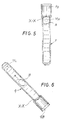
- the initial position of the container of the test tube type is shown in Fig. 5; the sensors 14 may be in the position 14X or already in the position 14L. In the rotated condition of the moving element 3, and therefore with a specific inclination of the container of the test tube type 9, with the end which is moved from the lowest position shown in Figs.
- An instrument similar to that described may be prepared to carry out a plurality of simultaneous measurements, by providing in the moving element 103, which is suitably shaped as shown in Fig. 4 for example, a plurality of housings for test tubes 9 positioned parallel to each other and by providing corresponding pluralities of pairs of sensor elements 114, to carry out the optical determinations in the individual test tubes.
Landscapes
- General Health & Medical Sciences (AREA)
- Health & Medical Sciences (AREA)
- Life Sciences & Earth Sciences (AREA)
- Chemical & Material Sciences (AREA)
- Analytical Chemistry (AREA)
- Biochemistry (AREA)
- Physics & Mathematics (AREA)
- General Physics & Mathematics (AREA)
- Immunology (AREA)
- Pathology (AREA)
- Sampling And Sample Adjustment (AREA)
- Automatic Analysis And Handling Materials Therefor (AREA)
- Optical Measuring Cells (AREA)
Claims (9)
- Instrument zum Messen der Viskosität einer Flüssigkeit, mit:einem beweglichen Element (3), das um eine Horizontalachse (X X) schwingen kann, auf einer Basisstruktur (1) ;wenigstens einem Gehäuse (7) auf dem beweglichen Element (3) zur Aufnahme eines abdichtbaren Behälters (9), der sich in Längsrichtung rechtwinkelig oder im Winkel zu der Horizontalachse (X-X) erstreckt und mit dem beweglichen Element (3) zwischen einer ersten Position und einer zweiten Position um die Horizontalachse (X-X) bewegbar ist;einem optischen Lesesystem (14) mittels Transparenz durch wenigstens einen Behälter (9), um die Anwesenheit von Gasblasen, welche das höhere Ende des Behälters erreichen, zu bestimmen;einem Zeitmeßinstrument;einem Raumwegmeßinstrument zum Messen des Raumweges der Blase entlang des Behälters;wobei das optische Lesesystem (14), das Zeitmeßinstrument und das Raumwegmeßsystem den Pegel der Flüssigkeit in dem Behälter bestimmen, wenn das bewegliche Element (3) in der ersten Position ist, und wenn das bewegliche Element (3) von der ersten Position in die zweite Position bewegt wird, diejenige Zeit detektiert wird, die die Blase braucht, um sich vom ersten Ende zu einem zweiten Ende des Behälters (9) zu bewegen.
- Instrument nach Anspruch 1, dadurch gekennzeichnet, daß das optische Lesesystem (14) auf dem beweglichen Element (3) angeordnet ist.
- Instrument nach Anspruch 2, dadurch gekennzeichnet, daß das optische Lesesystem (14) durch einen Gleitzeiger (12) getragen ist, der entlang der Längserstreckung des Behälters (9) verschiebbar ist.
- Instrument nach wenigstens Anspruch 3, dadurch gekennzeichnet, daß der Gleitzeiger einem System zum Messen der Höhe der Flüssigkeltssäule im Behälter (9) zugeordnet ist.
- Instrument nach Anspruch 3 oder 4, gekennzeichnet durch ein Antriebsystem (16, 18) mit einer Endlosschraube oder von einem ähnlichen Typ, für den Gleitzeiger (12) des optischen Lesesystems.
- Instrument nach wenigstens einem der vorstehenden Ansprüche, gekennzeichnet durch ein Antriebsystem (5) für die Rotation und/oder Schwingung des beweglichen Elementes (3).
- Instrument nach wenigstens einem der vorstehenden Ansprüche, dadurch gekennzeichnet, daß der Behälter vom Probenröhrchen - Typ (9) mit einem abgeflachten Querschnitt (9A) versehen ist, dessen größere Abmessung parallel zur Horizontalachse (X-X) der Schwingung des beweglichen Elementes (3) liegt.
- Verfahren zum Messen der Viskosität einer Flüssigkeit, basierend auf der Bestimmung der kinematischen Parameter der Bewegung einer Gasblase in der zu untersuchenden Flüssigkeit, wobei die Bewegung unter Wirkung der Gravitationskraft, des Fluiddruckes und der viskoelastischen Kräfte stattfindet, wobei das Verfahren die Schritte aufweist:Einleiten der Flüssigkeit in einen sich in Längsrichtung sich erstreckenden Behälter, der in derjenigen Richtung, in welche sich die Blase bewegt, eine begrenzte Abmessung hat,Abdichten des Behälters unter Belassung einer Gasblase in demselben;optisches Bestimmen des Flüssigkeitspegels in dem Behälter, wenn der Behälter in einer ersten Position ist;Schwenken des Behälters von der ersten Position in eine zweite Position;Bestimmen derjenigen Zeit, die die Blase benötigt, um von einem ersten Ende zu einem zweiten Ende des Behälters zu wandern, wenn der Behälter von der ersten Position in die zweite Position bewegt worden ist.
- Verfahren nach Anspruch 8, dadurch gekennzeichnet, daß auch eine Bewegung, die durch die Zentrifugalwirkung verursacht wird, vorgesehen ist.
Applications Claiming Priority (3)
| Application Number | Priority Date | Filing Date | Title |
|---|---|---|---|
| ITFI970244 | 1997-11-03 | ||
| IT97FI000244A IT1295677B1 (it) | 1997-11-03 | 1997-11-03 | Strumento e metodo per la misura della viscosita' di un liquido |
| PCT/IT1998/000305 WO1999023470A1 (en) | 1997-11-03 | 1998-10-30 | Instrument and method for measuring the viscosity of a liquid |
Publications (2)
| Publication Number | Publication Date |
|---|---|
| EP1029230A1 EP1029230A1 (de) | 2000-08-23 |
| EP1029230B1 true EP1029230B1 (de) | 2002-01-23 |
Family
ID=11352279
Family Applications (1)
| Application Number | Title | Priority Date | Filing Date |
|---|---|---|---|
| EP98951679A Expired - Lifetime EP1029230B1 (de) | 1997-11-03 | 1998-10-30 | Instrument und methode zur messung der viskosität einer flüssigkeit |
Country Status (6)
| Country | Link |
|---|---|
| EP (1) | EP1029230B1 (de) |
| AT (1) | ATE212437T1 (de) |
| AU (1) | AU9761298A (de) |
| DE (1) | DE69803602D1 (de) |
| IT (1) | IT1295677B1 (de) |
| WO (1) | WO1999023470A1 (de) |
Families Citing this family (2)
| Publication number | Priority date | Publication date | Assignee | Title |
|---|---|---|---|---|
| CN106323814B (zh) * | 2015-06-19 | 2018-11-30 | 中国石油化工股份有限公司 | 一种测量稠油粘度的方法 |
| US12366554B2 (en) | 2021-09-15 | 2025-07-22 | Saudi Arabian Oil Company | Gaseous bubble system and method to measure gelation time |
Family Cites Families (5)
| Publication number | Priority date | Publication date | Assignee | Title |
|---|---|---|---|---|
| GB1210804A (en) * | 1967-03-13 | 1970-11-04 | Courtaulds Ltd | Viscometers |
| DE2946453A1 (de) * | 1979-11-17 | 1981-05-27 | Bayer Ag, 5090 Leverkusen | Fallkoerperviskosimeter |
| DE3219706A1 (de) * | 1982-05-26 | 1983-12-01 | Jürgen Prof. 7302 Ostfildern Mauch | Vorrichtung zum vergleichenden beobachten der viskositaeten verschiedener fluessigkeiten |
| US4648262A (en) * | 1985-03-07 | 1987-03-10 | Reis August K | Microviscosimeter |
| US5289716A (en) * | 1992-08-21 | 1994-03-01 | The United States Of America As Represented By The United States Department Of Energy | Monitoring and analyzing waste glass compositions |
-
1997
- 1997-11-03 IT IT97FI000244A patent/IT1295677B1/it active IP Right Grant
-
1998
- 1998-10-30 EP EP98951679A patent/EP1029230B1/de not_active Expired - Lifetime
- 1998-10-30 WO PCT/IT1998/000305 patent/WO1999023470A1/en not_active Ceased
- 1998-10-30 AU AU97612/98A patent/AU9761298A/en not_active Abandoned
- 1998-10-30 AT AT98951679T patent/ATE212437T1/de not_active IP Right Cessation
- 1998-10-30 DE DE69803602T patent/DE69803602D1/de not_active Expired - Lifetime
Also Published As
| Publication number | Publication date |
|---|---|
| IT1295677B1 (it) | 1999-05-24 |
| DE69803602D1 (de) | 2002-03-14 |
| ITFI970244A0 (it) | 1997-11-03 |
| EP1029230A1 (de) | 2000-08-23 |
| ITFI970244A1 (it) | 1999-05-03 |
| AU9761298A (en) | 1999-05-24 |
| WO1999023470A1 (en) | 1999-05-14 |
| ATE212437T1 (de) | 2002-02-15 |
Similar Documents
| Publication | Publication Date | Title |
|---|---|---|
| Rosencranz et al. | Clinical laboratory measurement of serum, plasma, and blood viscosity | |
| US20020088953A1 (en) | Dual riser/dual capillary viscometer for newtonian and non-newtonian fluids | |
| CA1133721A (en) | Method and apparatus for field measurement of interfacial tension between immiscible fluids | |
| US9733174B2 (en) | Capillary microviscometer | |
| GB2172702A (en) | Capillary tube viscometer with photo electric sensing | |
| KR920003040B1 (ko) | 자동점도 측정장치 | |
| JP2021001762A (ja) | 液体採取装置、マイクロ流体チップ、粘度測定方法および表面張力測定方法 | |
| US5847268A (en) | Viscosity measuring apparatus and method | |
| EP1029230B1 (de) | Instrument und methode zur messung der viskosität einer flüssigkeit | |
| KR100533598B1 (ko) | 혈구 유변계 | |
| JP2002062239A (ja) | 粘度測定装置 | |
| US5447063A (en) | Liquid density monitoring apparatus | |
| KR100353425B1 (ko) | 로드셀에 의한 질량 연속측정식 모세관 점도계 | |
| Lashkari et al. | Development of a fully automated soap flowmeter for micro flow measurements | |
| US4942759A (en) | Viscosity testing apparatus | |
| KR20020095145A (ko) | 마이크로 점도계 및 측정방법 | |
| JP2022150524A (ja) | 動粘度や密度に対する表面張力を測定するシステム、および測定する方法 | |
| RU2094770C1 (ru) | Вискозиметр | |
| CA2166914C (en) | Single sensor density measuring apparatus and method | |
| WO2003058210A1 (en) | Dual capillary viscometer for newtonian and non-newtonian fluids | |
| SU616560A1 (ru) | Шариковый вискозиметр | |
| KR20190043995A (ko) | 혈액분석장치 | |
| SU1239551A1 (ru) | Вискозиметр | |
| US20250224264A1 (en) | Method for measuring flow property of liquid and measuring instrument | |
| SU1221552A1 (ru) | Вискозиметр |
Legal Events
| Date | Code | Title | Description |
|---|---|---|---|
| PUAI | Public reference made under article 153(3) epc to a published international application that has entered the european phase |
Free format text: ORIGINAL CODE: 0009012 |
|
| 17P | Request for examination filed |
Effective date: 20000518 |
|
| AK | Designated contracting states |
Kind code of ref document: A1 Designated state(s): AT BE CH DE DK ES FI FR GB GR IT LI NL PT SE |
|
| GRAG | Despatch of communication of intention to grant |
Free format text: ORIGINAL CODE: EPIDOS AGRA |
|
| 17Q | First examination report despatched |
Effective date: 20010209 |
|
| GRAG | Despatch of communication of intention to grant |
Free format text: ORIGINAL CODE: EPIDOS AGRA |
|
| GRAH | Despatch of communication of intention to grant a patent |
Free format text: ORIGINAL CODE: EPIDOS IGRA |
|
| GRAH | Despatch of communication of intention to grant a patent |
Free format text: ORIGINAL CODE: EPIDOS IGRA |
|
| GRAA | (expected) grant |
Free format text: ORIGINAL CODE: 0009210 |
|
| REG | Reference to a national code |
Ref country code: GB Ref legal event code: IF02 |
|
| AK | Designated contracting states |
Kind code of ref document: B1 Designated state(s): AT BE CH DE DK ES FI FR GB GR IT LI NL PT SE |
|
| PG25 | Lapsed in a contracting state [announced via postgrant information from national office to epo] |
Ref country code: NL Free format text: LAPSE BECAUSE OF FAILURE TO SUBMIT A TRANSLATION OF THE DESCRIPTION OR TO PAY THE FEE WITHIN THE PRESCRIBED TIME-LIMIT Effective date: 20020123 Ref country code: LI Free format text: LAPSE BECAUSE OF FAILURE TO SUBMIT A TRANSLATION OF THE DESCRIPTION OR TO PAY THE FEE WITHIN THE PRESCRIBED TIME-LIMIT Effective date: 20020123 Ref country code: GR Free format text: LAPSE BECAUSE OF FAILURE TO SUBMIT A TRANSLATION OF THE DESCRIPTION OR TO PAY THE FEE WITHIN THE PRESCRIBED TIME-LIMIT Effective date: 20020123 Ref country code: FR Free format text: LAPSE BECAUSE OF FAILURE TO SUBMIT A TRANSLATION OF THE DESCRIPTION OR TO PAY THE FEE WITHIN THE PRESCRIBED TIME-LIMIT Effective date: 20020123 Ref country code: FI Free format text: LAPSE BECAUSE OF FAILURE TO SUBMIT A TRANSLATION OF THE DESCRIPTION OR TO PAY THE FEE WITHIN THE PRESCRIBED TIME-LIMIT Effective date: 20020123 Ref country code: CH Free format text: LAPSE BECAUSE OF FAILURE TO SUBMIT A TRANSLATION OF THE DESCRIPTION OR TO PAY THE FEE WITHIN THE PRESCRIBED TIME-LIMIT Effective date: 20020123 Ref country code: BE Free format text: LAPSE BECAUSE OF FAILURE TO SUBMIT A TRANSLATION OF THE DESCRIPTION OR TO PAY THE FEE WITHIN THE PRESCRIBED TIME-LIMIT Effective date: 20020123 Ref country code: AT Free format text: LAPSE BECAUSE OF FAILURE TO SUBMIT A TRANSLATION OF THE DESCRIPTION OR TO PAY THE FEE WITHIN THE PRESCRIBED TIME-LIMIT Effective date: 20020123 |
|
| REF | Corresponds to: |
Ref document number: 212437 Country of ref document: AT Date of ref document: 20020215 Kind code of ref document: T |
|
| REG | Reference to a national code |
Ref country code: CH Ref legal event code: EP |
|
| REF | Corresponds to: |
Ref document number: 69803602 Country of ref document: DE Date of ref document: 20020314 |
|
| RAP2 | Party data changed (patent owner data changed or rights of a patent transferred) |
Owner name: DIESSE DIAGNOSTICA SENESE S.P.A. |
|
| PG25 | Lapsed in a contracting state [announced via postgrant information from national office to epo] |
Ref country code: SE Free format text: LAPSE BECAUSE OF FAILURE TO SUBMIT A TRANSLATION OF THE DESCRIPTION OR TO PAY THE FEE WITHIN THE PRESCRIBED TIME-LIMIT Effective date: 20020423 Ref country code: PT Free format text: LAPSE BECAUSE OF FAILURE TO SUBMIT A TRANSLATION OF THE DESCRIPTION OR TO PAY THE FEE WITHIN THE PRESCRIBED TIME-LIMIT Effective date: 20020423 Ref country code: DK Free format text: LAPSE BECAUSE OF FAILURE TO SUBMIT A TRANSLATION OF THE DESCRIPTION OR TO PAY THE FEE WITHIN THE PRESCRIBED TIME-LIMIT Effective date: 20020423 |
|
| PG25 | Lapsed in a contracting state [announced via postgrant information from national office to epo] |
Ref country code: DE Free format text: LAPSE BECAUSE OF FAILURE TO SUBMIT A TRANSLATION OF THE DESCRIPTION OR TO PAY THE FEE WITHIN THE PRESCRIBED TIME-LIMIT Effective date: 20020424 |
|
| NLT2 | Nl: modifications (of names), taken from the european patent patent bulletin |
Owner name: DIESSE DIAGNOSTICA SENESE S.P.A. |
|
| NLV1 | Nl: lapsed or annulled due to failure to fulfill the requirements of art. 29p and 29m of the patents act | ||
| PG25 | Lapsed in a contracting state [announced via postgrant information from national office to epo] |
Ref country code: ES Free format text: LAPSE BECAUSE OF FAILURE TO SUBMIT A TRANSLATION OF THE DESCRIPTION OR TO PAY THE FEE WITHIN THE PRESCRIBED TIME-LIMIT Effective date: 20020730 |
|
| REG | Reference to a national code |
Ref country code: CH Ref legal event code: PL |
|
| PG25 | Lapsed in a contracting state [announced via postgrant information from national office to epo] |
Ref country code: GB Free format text: LAPSE BECAUSE OF NON-PAYMENT OF DUE FEES Effective date: 20021030 |
|
| EN | Fr: translation not filed | ||
| PLBE | No opposition filed within time limit |
Free format text: ORIGINAL CODE: 0009261 |
|
| STAA | Information on the status of an ep patent application or granted ep patent |
Free format text: STATUS: NO OPPOSITION FILED WITHIN TIME LIMIT |
|
| 26N | No opposition filed | ||
| NLT2 | Nl: modifications (of names), taken from the european patent patent bulletin |
Owner name: DIESSE DIAGNOSTICA SENESE S.P.A. |
|
| GBPC | Gb: european patent ceased through non-payment of renewal fee | ||
| PG25 | Lapsed in a contracting state [announced via postgrant information from national office to epo] |
Ref country code: IT Free format text: LAPSE BECAUSE OF NON-PAYMENT OF DUE FEES Effective date: 20051030 |