EP1029476B1 - Kühlregal - Google Patents
Kühlregal Download PDFInfo
- Publication number
- EP1029476B1 EP1029476B1 EP00100405A EP00100405A EP1029476B1 EP 1029476 B1 EP1029476 B1 EP 1029476B1 EP 00100405 A EP00100405 A EP 00100405A EP 00100405 A EP00100405 A EP 00100405A EP 1029476 B1 EP1029476 B1 EP 1029476B1
- Authority
- EP
- European Patent Office
- Prior art keywords
- cover
- cover sheet
- access opening
- display stand
- refrigerated display
- Prior art date
- Legal status (The legal status is an assumption and is not a legal conclusion. Google has not performed a legal analysis and makes no representation as to the accuracy of the status listed.)
- Expired - Lifetime
Links
- 238000000576 coating method Methods 0.000 claims abstract description 7
- 239000011248 coating agent Substances 0.000 claims abstract description 6
- 239000013039 cover film Substances 0.000 claims description 53
- 238000007789 sealing Methods 0.000 claims description 24
- 230000005855 radiation Effects 0.000 claims description 4
- 239000010410 layer Substances 0.000 description 50
- 238000001816 cooling Methods 0.000 description 31
- 239000003570 air Substances 0.000 description 26
- 239000010408 film Substances 0.000 description 7
- 238000005096 rolling process Methods 0.000 description 5
- 238000009833 condensation Methods 0.000 description 4
- 230000005494 condensation Effects 0.000 description 4
- 239000011888 foil Substances 0.000 description 4
- 239000002184 metal Substances 0.000 description 3
- 230000000694 effects Effects 0.000 description 2
- 238000009413 insulation Methods 0.000 description 2
- 239000012212 insulator Substances 0.000 description 2
- 239000002356 single layer Substances 0.000 description 2
- 230000004308 accommodation Effects 0.000 description 1
- 239000000853 adhesive Substances 0.000 description 1
- 230000001070 adhesive effect Effects 0.000 description 1
- 239000012080 ambient air Substances 0.000 description 1
- 230000015572 biosynthetic process Effects 0.000 description 1
- 230000003203 everyday effect Effects 0.000 description 1
- 238000002474 experimental method Methods 0.000 description 1
- 239000003973 paint Substances 0.000 description 1
- 229920006255 plastic film Polymers 0.000 description 1
- 239000002990 reinforced plastic Substances 0.000 description 1
- 239000000725 suspension Substances 0.000 description 1
Images

Classifications
-
- A—HUMAN NECESSITIES
- A47—FURNITURE; DOMESTIC ARTICLES OR APPLIANCES; COFFEE MILLS; SPICE MILLS; SUCTION CLEANERS IN GENERAL
- A47F—SPECIAL FURNITURE, FITTINGS, OR ACCESSORIES FOR SHOPS, STOREHOUSES, BARS, RESTAURANTS OR THE LIKE; PAYING COUNTERS
- A47F3/00—Show cases or show cabinets
- A47F3/04—Show cases or show cabinets air-conditioned, refrigerated
- A47F3/0439—Cases or cabinets of the open type
- A47F3/0469—Details, e.g. night covers
Definitions
- the invention relates to a cooling shelf with an access opening, which can be closed by a cover device is.
- Cooling shelves are used for refrigerated storage and presentation of Goods in grocery stores.
- the cooling shelves are in the Usually from a shelf with several shelves, which by closed at the bottom, top, side and rear by refrigerated shelves and has an access opening towards the front, through the goods lying on the shelves can be taken directly from customers.
- the interior of the Cooling shelves are cooled, for example, by circulating air cooling. Because of the large access opening there are cold losses of the cooling shelf considerably. For this reason, the cooling shelf outside the access times, i.e. usually between Closure and opening of the grocery store through a Cover device closed. Because of the small space requirement have flexible cover films as a cover device enforced, which are designed as roller blind devices.
- the Covering roller blind is pulled out during non-access times and in this way in front of or in the access opening stretched so that the cold losses by preventing the Air exchange between the cooling rack interior and the surrounding area considerably be reduced. Because of the low temperature of the clamped by the cooling air cooled cover film compared to the Ambient air forms on the outside of the cover film the ambient humidity condensate that when rolling up the cover film interferes and the durability of the cover film reduced. To prevent condensation, perforated Covering films used by the cooling air from the interior of the refrigerated shelves can pass through so that the condensation of humidity on the outside of the cover film is prevented. However, by emanating from Cooling air through the perforation causes considerable cold losses.
- the Access opening can be closed by a cover device, which is formed from a curtain of two layers.
- the two Layers are made of flexible cover film and are in the Access opening spanned spaced apart.
- the Cover device has suspension eyes on its upper longitudinal side with which they are hung on hooks or with which it can be removed from the hook. For accommodation the cover device when not in use becomes a separate one Storage space needed.
- the covering device is subject to the Significant wear and tear every day. The opening and Hanging out also involves effort and cannot be carried out automatically.
- a cooling shelf is described in US-A-4,288,992 and shown, the access opening by a single-layer curtain is closable. A drive to open and closing the curtain is not described.
- the object of the invention is for a refrigerated shelf with an access opening to create an improved covering device.
- the covering device is designed as a roller blind device, so that the two layers of cover film from one edge of the Access opening are extendable to the opposite edge.
- the blind device is preferably at the top of the Access opening mounted so that the cover film layers for Seal from the top to the bottom of the Access opening can be pulled out. That way an easy-to-use and space-saving covering device realized.
- the blind device is like a pulley formed, with a single cover the two Forms cover layers, and a cylindrical fixed Roller roll for rolling up and rolling off the cover film and one cylindrical loose roll between the two layers of cover film is provided. While the fixed role the opening and Unrolling the cover film is used, the loose roll of the Cover foil wrapped around 180 °. The loose roll ensures So for a deflection of the cover film by 180 °, for a Smooth out the cover film and at the same time for one Distance between the two layers of cover film.
- the Covering film is thus with one end on the fixed Roll attached and roll on this or from this unrolled. The other end of the cover film is on the Blind device or attached in their vicinity.
- the cooling shelf according to the invention has a covering device for the access opening next to the first layer of flexible cover film a second layer of flexible cover film, which in one certain distance from the first cover sheet layer can be clamped in front of or in the access opening.
- the Access opening is through a double layer of cover film closable, with an insulating air cushion between the layers is formed.
- the cold insulation of the two-layer covering device is opposite a single-layer covering device has been significantly improved, because the air cushion between the two layers is a good heat insulator against convection cold losses.
- the cold losses can be significantly reduced in this way.
- the two-ply cover device the temperature difference between the outside and the inside each layer significantly reduced, so that the respective No more condensate settles on the outside of each cover sheet. There is no need to perforate the cover film layer, which is why the cold losses by another significant Amount are reduced. Due to the double-layer design of the Covering film is thus achieved two different effects add up to a significant reduction in cold losses.
- the cover film layers are preferably vertical for closing extendable in front of the access opening.
- the distance between the Cover foil layers almost the same everywhere and is between 1.0 and 20.0 cm, especially about 2.0 cm.
- the roller blind device preferably has a drive for opening and closing Pull in the cover foil layers.
- the pulley system is preferably the fixed rotatable Roller for rolling up and unrolling the cover film driven. It
- the loosely rotatable roller can also be in the closed position Cover device or in the opposite direction by the drive be moved.
- the fixed role a rotary drive.
- a cover film layer has a flexible sealing tape on each side edge on, each with a fixed sealing strip on the side edges the access opening interacts magnetically in such a way that the side edge of the extended cover sheet layer each rests on the sealing strip.
- the sealing tape can, for example a magnetizable metal mesh strip or equivalent be metallic paint in the edge area of the cover sheet concerned is sewn on or glued on.
- the sealing strip can consist of a permanent magnet that runs along the side edges the access opening is continuously attached. On in this way, the side edges of the cover sheet are covered the sealing strip is magnetically attracted so that it is largely sealing rest on the sealing strip. This makes a gap-free Closure of the side edges of the access opening also realized, thereby avoiding further cold losses.
- the fixed cover film layer has the pulley-like roller blind device Sealing tape, which attach to the sealing strip without friction and has it peeled off.
- the combination of the pulley system with the magnetic seal is therefore particularly advantageous because the pulley-like A cover sheet layer is always fixed, which is why this situation is not pushed as such, but to a certain extent is placed on the cover opening. For this Reason can be fixed with the fixed layer of cover film seal connecting to the side edges of the access opening realize.
- the cover film is preferably designed to be airtight. A Perforation of the cover film to avoid condensation not because of the air cushion between the cover film layers more needed. Therefore, the cover film can be absolutely airtight be trained, which in turn reduces cold losses become.
- the cover film layers are one-sided reflective with infrared radiation Provide coating, which are arranged opposite each other are.
- the coating is therefore always an air cushion directed between the two layers of cover film. Like attempts have resulted are the heat radiation losses through the Cover layers through this arrangement the least.
- a cooling shelf 10 is shown, the one so-called vertical sales cooling rack with forced-air cooling.
- Cooling shelves are used in grocery stores, to store goods to be cooled and at the same time suitable for sale showcase.
- the cooling shelf 10 shown in Fig. 1 has a bottom wall 12, a back wall 13, a top wall 14 and two side walls 15, which together enclose a cooling space 16.
- At the Back wall 13 are two shelves that are inclined slightly downward towards the front 18 arranged.
- the front of the refrigerated shelf 10 has one extending substantially over the entire front Access opening 20 through which a customer directly can access the refrigerated goods stored in the interior 16.
- the cooling shelf 10 has a forced air cooling, which is formed in the is from an air inlet 22 on the bottom opening edge, the Floor duct 23, in the course of which a fan 24 and a cooling device 25 are arranged.
- the sucked in through the air inlet 22 and cooled air by the cooling device 25 further through a rear wall channel 27 and an adjoining one Ceiling wall duct 29 led to an air outlet 32.
- the cooled air flows through the air outlet 32 and forms in the access opening 20 a cold air curtain between the Cold air outlet 32 and the cold air inlet 22.
- Rear wall channel 27 are further openings to the interior side provided by the cooling air directly into the cooling space 16 and in particular flows directly onto the shelves 18.
- a cover device 40 is in the Ceiling wall 14 installed.
- the cover device is a roller blind device which contains a cover film 42, that as a night cover for closing the access opening 20 can be lowered into the access opening 20.
- the cover device 40 a roller blind designed as a pulley system.
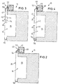
- the roller blind device has a single flexible cover film 42 on in the closed state (FIG. 4) of the blind device 40 a first inner cover sheet layer 44 and a second outside cover sheet layer 46 forms.
- a layer is formed between the two cover film layers 44, 46 air-filled space 47, which is a good heat insulator releases and thus cold losses of the cooling rack interior 16 counteracts. Furthermore, through the gap air cushion 47 also the formation of condensate on the respective warmer Sides of the cover foil layers 44,46 prevented.
- the roller blind device 40 has a fixed, rotatable, cylindrical one Roll 48 on the top of the access opening 20 is arranged.
- the fixed roller 48 has an electric one Rotary drive on, through which the cover film is rolled up and down can be. While the one end of the cover sheet 42 firmly the fixed roller 48 is attached, the other end 50 is the Cover film 42 firmly on the housing 52 of the cover device 40 attached.
- a loose second rotatable cylindrical one Roll 54 provided that serves as a weighting role. The second roller 54 pulls the two layers due to its own weight 44,46 down so that the cover sheet 42 is vertical and is spanned smoothly in the access opening 20, as in 3 and 4 are shown.
- the cover sheet 42 is an airtight, flexible and Fabric-reinforced plastic film that is one-sided with infrared radiation reflective coating is provided.
- the Coating is on the side facing the space the cover sheet layers 44,46 applied.
- the loose roller 54 has a diameter of approximately 2.0 cm.
- the two film layers are also at the upper end of the access opening 20 44.46 stored at a distance of approximately 2.0 cm, so that a largely constant air cushion of 2.0 cm thick.
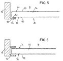
- FIGS. 1-4 40 are two embodiments of one Edge sealing of the roller blind devices shown in FIGS. 1-4 40 shown.
- the cover film 60 shown in FIG. 5 has on the outside the outer second cover sheet layer 66 as a sealing tape a flexible metal band 62 that extends over the entire height the access opening 20 extends.
- a magnetic sealing strip 65 over the entire Height of the access opening 20 is arranged.
- the metal sealing tape 62 lies on the gap-free magnetic sealing strip 65, which ensures a gap-free seal in the edge area.
- the frictionless creation of the rolled Cover film 60 is possible because the second Cover sheet layer 66 is vertically fixed to the cover device housing 52 is attached, as can be seen in Fig. 2-4. When rolling up the cover film 60 peels off the cover film layer 66 from the sealing strip 65 without friction.
- a labyrinth seal is shown, which is essentially is formed from a vertical U-profile 72, in the side opening of the side edges of the two layers of cover film 74, 76 and the respective end of the loose roll 54 plunge.
- the labyrinth seal shown also offers one good sealing against convection cold losses and serves at the same time as a guide for the roller 54 and the cover film 70th
Landscapes
- Physics & Mathematics (AREA)
- Thermal Sciences (AREA)
- Refrigerator Housings (AREA)
- Freezers Or Refrigerated Showcases (AREA)
- Laminated Bodies (AREA)
- Devices That Are Associated With Refrigeration Equipment (AREA)
- Temperature-Responsive Valves (AREA)
- Cold Air Circulating Systems And Constructional Details In Refrigerators (AREA)
Description
- Fig. 1
- eine Querschnittsdarstellung eines Kühlregales mit einer fest eingebauten Flaschenzug-Rollovorrichtung,
- Fig. 2
- schematisch Kühlregal mit angebauter und vollständig aufgerollter Rollovorrichtung,
- Fig. 3
- das Kühlregal der Figur 2 mit halb ausgerollter Rollovorrichtung,
- Fig. 4
- das Kühlregal der Figur 2 mit vollständig ausgerollter Rollovorrichtung,
- Fig. 5
- ein Längsschnitt der Abdichtfolie und ihrer seitlichen Magnet-Abdichtung,
- Fig. 6
- ein zweites Ausführungsbeispiel für die seitliche Abdichtung der Abdeckfolie mit Labyrinthdichtung.
Claims (9)
- Kühlregal mit einer Zugriffsöffnung (20), die durch eine Abdeckvorrichtung (40) verschließbar ist,
wobei die Abdeckvorrichtung (40) eine erste Lage (44) flexibler Abdeckfolie (42) aufweist, die zum Verschließen der Zugriffsöffnung (20) in der Zugriffsöffnung (20) aufspannbar ist, wobei
die Abdeckvorrichtung (40) eine zweite Lage (46) flexibler Abdeckfolie (42) aufweist, die in der Zugriffsöffnung (20) und beabstandet von der ersten Lage (44) aufspannbar ist,
dadurch gekennzeichnet , dass die Abdeckvorrichtung (40) als Rollovorrichtung ausgebildet ist, und
dass die Rollovorrichtung (40) nach Art eines Flaschenzuges ausgebildet ist, wobei eine einzige Abdeckfolie (42) die beiden Abdeckfolienlagen (44,46) bildet, und eine zylinderartige feststehende drehbare Rolle (48) zum Aufund Abrollen der Abdeckfolie (42) sowie eine zylinderartige lose drehbare Rolle (54) zwischen den beiden Abdeckfolienlagen (44,46) vorgesehen sind. - Kühlregal nach Anspruch 1, dadurch gekennzeichnet, dass die Abdeckfolienlagen (44,46) zum Verschließen senkrecht vor der Zugriffsöffnung ausziehbar sind.
- Kühlregal nach Anspruch 1 oder 2, dadurch gekennzeichnet, dass der Abstand zwischen den beiden Abdeckfolienlagen (44,46) überall annähernd gleich ist und zwischen 1,0 und 20,0 cm beträgt, insbesondere ungefähr 2,0 cm.
- Kühlregal nach einem der Ansprüche 1-3, dadurch gekennzeichnet, dass die Rollovorrichtung (40) einen Antrieb zum Aus- und Einziehen der Abdeckfolienlagen (44,46) aufweist.
- Kühlregal nach Anspruch 4, dadurch gekennzeichnet, dass die feststehende Rolle (48) einen Drehantrieb aufweist.
- Kühlregal nach einem der Ansprüche 1-5, dadurch gekennzeichnet, dass eine der Abdeckfolienlagen (66) an ihren Seitenrändern jeweils ein flexibles Dichtband (62) aufweist, das jeweils mit einer festen Dichtleiste (65) an den Seitenrändern (63) der Zugriffsöffnung (20) magnetisch zusammenwirkt, so dass die Seitenränder (63) der ausgezogenen Abdeckfolienlage (66) jeweils an der Dichtleiste (65) anliegen.
- Kühlregal nach Anspruch 6, dadurch gekennzeichnet, dass eine Abdeckfolienlage (66) fest am Kühlgerätrahmen befestigt ist und das Dichtband (62) aufweist, das sich friktionsfrei an die Dichtleiste (65) anlegen und von ihr abschälen lässt.
- Kühlregal nach einem der Ansprüche 1-7, dadurch gekennzeichnet, dass die Abdeckfolie (42) luftdicht ist.
- Kühlregal nach einem der Ansprüche 1-8, dadurch gekennzeichnet, dass die Abdeckfolienlagen (44,46) einseitig jeweils eine Infrarotstrahlung reflektierende Beschichtung aufweisen, die einander gegenüberliegend angeordnet sind.
Applications Claiming Priority (2)
| Application Number | Priority Date | Filing Date | Title |
|---|---|---|---|
| DE29902999U | 1999-02-19 | ||
| DE29902999U DE29902999U1 (de) | 1999-02-19 | 1999-02-19 | Kühlregal |
Publications (3)
| Publication Number | Publication Date |
|---|---|
| EP1029476A2 EP1029476A2 (de) | 2000-08-23 |
| EP1029476A3 EP1029476A3 (de) | 2001-02-28 |
| EP1029476B1 true EP1029476B1 (de) | 2003-12-03 |
Family
ID=8069657
Family Applications (1)
| Application Number | Title | Priority Date | Filing Date |
|---|---|---|---|
| EP00100405A Expired - Lifetime EP1029476B1 (de) | 1999-02-19 | 2000-01-08 | Kühlregal |
Country Status (3)
| Country | Link |
|---|---|
| EP (1) | EP1029476B1 (de) |
| AT (1) | ATE255350T1 (de) |
| DE (2) | DE29902999U1 (de) |
Families Citing this family (6)
| Publication number | Priority date | Publication date | Assignee | Title |
|---|---|---|---|---|
| DE20000012U1 (de) * | 2000-01-03 | 2000-03-16 | Linde Ag, 65189 Wiesbaden | Warenpräsentationsmöbel mit einer schwenkbaren Blende |
| DE10118439A1 (de) * | 2001-04-12 | 2002-10-17 | Linde Ag | Kühlregal |
| DE10221604B4 (de) * | 2002-05-15 | 2010-09-16 | Linde Kältetechnik GmbH & Co. KG | Warenpräsentationsmöbel mit Nachtrollo |
| DE102009055724A1 (de) * | 2009-11-26 | 2011-06-01 | Albert Weiss | Rolloeinrichtung |
| US9372025B2 (en) | 2012-10-22 | 2016-06-21 | Anthony, Inc. | Covers for refrigeration systems |
| CN109982613B (zh) * | 2016-10-31 | 2021-01-26 | 开利公司 | 冷藏销售柜 |
Family Cites Families (8)
| Publication number | Priority date | Publication date | Assignee | Title |
|---|---|---|---|---|
| DE1897945U (de) * | 1964-05-25 | 1964-08-06 | Amberger Kuehlanlagen Maschine | Kuehlmoebel. |
| GB1555306A (en) * | 1975-07-03 | 1979-11-07 | Shade One Ltd | Refrigerated display containers |
| US4275645A (en) * | 1978-07-10 | 1981-06-30 | Expertise Assistance Inc. | Closure for service opening |
| US4288992A (en) * | 1980-02-19 | 1981-09-15 | Eliason Corporation | Curtain for open front freezer or refrigerator |
| JPS57131969A (en) * | 1981-02-06 | 1982-08-16 | Hitoshi Karashima | Freeze refrigerated display cabinet |
| DE8712220U1 (de) * | 1987-09-09 | 1987-10-22 | Remis Gesellschaft für Entwicklung und Vertrieb von technischen Elementen mbH Köln, 5000 Köln | Kühlmöbelabdeckung |
| DE4127995C2 (de) * | 1990-10-03 | 1994-01-27 | Geta Ges Fuer Energietechnik U | Wärmedämmende Abdeckung an Kühlregalen |
| DE29804329U1 (de) * | 1998-03-11 | 1998-05-14 | Linde Ag, 65189 Wiesbaden | Nachtabdeckung für ein Kühlmöbel und Kühlmöbel |
-
1999
- 1999-02-19 DE DE29902999U patent/DE29902999U1/de not_active Expired - Lifetime
-
2000
- 2000-01-08 EP EP00100405A patent/EP1029476B1/de not_active Expired - Lifetime
- 2000-01-08 AT AT00100405T patent/ATE255350T1/de not_active IP Right Cessation
- 2000-01-08 DE DE50004606T patent/DE50004606D1/de not_active Expired - Fee Related
Also Published As
| Publication number | Publication date |
|---|---|
| EP1029476A2 (de) | 2000-08-23 |
| DE50004606D1 (de) | 2004-01-15 |
| ATE255350T1 (de) | 2003-12-15 |
| DE29902999U1 (de) | 2000-06-29 |
| EP1029476A3 (de) | 2001-02-28 |
Similar Documents
| Publication | Publication Date | Title |
|---|---|---|
| EP1355035B1 (de) | Rollosystem | |
| DE3016703A1 (de) | Gekuehlte lebensmittelschaustellungs und verkaufsvitrine | |
| DE2649934C3 (de) | Luftdruckregeleinrichtung | |
| EP0363454B1 (de) | Bespannung für das abdecken einer öffnung | |
| DE1451082B1 (de) | Abdeckung fuer ein Kuehlmoebel | |
| DE19546984C2 (de) | Tiefkühl- und/oder Kühlschrank | |
| EP1029476B1 (de) | Kühlregal | |
| DE102011010967A1 (de) | Spaltfreie Rolloeinrichtung | |
| DE3111110A1 (de) | Kuehlvitrine | |
| DE102009011578B3 (de) | Rollladenbespannung | |
| DE29804329U1 (de) | Nachtabdeckung für ein Kühlmöbel und Kühlmöbel | |
| DE19848395C2 (de) | Kühlmöbel mit einer Abdeckung | |
| DE20101977U1 (de) | Kühlregal | |
| DE8712220U1 (de) | Kühlmöbelabdeckung | |
| EP0063541A2 (de) | Aufrollbarer Doppelvorhang | |
| EP1718188B1 (de) | Kühltruhe mit nacht-rollo | |
| DE102010031082A1 (de) | Rolloeinrichtung | |
| DE10021656A1 (de) | Rolloeinrichtung | |
| EP1142518B1 (de) | Warenpräsentationsmöbel mit Displayaufsatz | |
| EP0252307B1 (de) | Kühlmöbel | |
| DE10023630A1 (de) | Rollartige Vorrichtung zum vorübergehenden Bedecken von Fenstern oder Glastüren sowie Rolläden in Gebäuden | |
| DE20316553U1 (de) | Kühlregal mit Nachtabdeckung | |
| WO2005074757A1 (de) | Kühlmöbel mit nachtabdeckung | |
| DE10013837B4 (de) | Zumindest teilweise gekühltes Warenpräsentationsmöbel mit wenigstens einer Abdeckung | |
| DE1451082C (de) | Abdeckung für ein Kühlmöbel |
Legal Events
| Date | Code | Title | Description |
|---|---|---|---|
| PUAI | Public reference made under article 153(3) epc to a published international application that has entered the european phase |
Free format text: ORIGINAL CODE: 0009012 |
|
| AK | Designated contracting states |
Kind code of ref document: A2 Designated state(s): AT BE CH CY DE DK ES FI FR GB GR IE IT LI LU MC NL PT SE |
|
| AX | Request for extension of the european patent |
Free format text: AL;LT;LV;MK;RO;SI |
|
| PUAL | Search report despatched |
Free format text: ORIGINAL CODE: 0009013 |
|
| AK | Designated contracting states |
Kind code of ref document: A3 Designated state(s): AT BE CH CY DE DK ES FI FR GB GR IE IT LI LU MC NL PT SE |
|
| AX | Request for extension of the european patent |
Free format text: AL;LT;LV;MK;RO;SI |
|
| 17P | Request for examination filed |
Effective date: 20010406 |
|
| AKX | Designation fees paid |
Free format text: AT BE CH CY DE DK ES FI FR GB GR IE IT LI LU MC NL PT SE |
|
| 17Q | First examination report despatched |
Effective date: 20030110 |
|
| GRAH | Despatch of communication of intention to grant a patent |
Free format text: ORIGINAL CODE: EPIDOS IGRA |
|
| GRAA | (expected) grant |
Free format text: ORIGINAL CODE: 0009210 |
|
| GRAS | Grant fee paid |
Free format text: ORIGINAL CODE: EPIDOSNIGR3 |
|
| AK | Designated contracting states |
Kind code of ref document: B1 Designated state(s): AT BE CH CY DE DK ES FI FR GB GR IE IT LI LU MC NL PT SE |
|
| PG25 | Lapsed in a contracting state [announced via postgrant information from national office to epo] |
Ref country code: NL Free format text: LAPSE BECAUSE OF FAILURE TO SUBMIT A TRANSLATION OF THE DESCRIPTION OR TO PAY THE FEE WITHIN THE PRESCRIBED TIME-LIMIT Effective date: 20031203 Ref country code: IE Free format text: LAPSE BECAUSE OF FAILURE TO SUBMIT A TRANSLATION OF THE DESCRIPTION OR TO PAY THE FEE WITHIN THE PRESCRIBED TIME-LIMIT Effective date: 20031203 Ref country code: GB Free format text: LAPSE BECAUSE OF FAILURE TO SUBMIT A TRANSLATION OF THE DESCRIPTION OR TO PAY THE FEE WITHIN THE PRESCRIBED TIME-LIMIT Effective date: 20031203 Ref country code: FR Free format text: LAPSE BECAUSE OF FAILURE TO SUBMIT A TRANSLATION OF THE DESCRIPTION OR TO PAY THE FEE WITHIN THE PRESCRIBED TIME-LIMIT Effective date: 20031203 Ref country code: FI Free format text: LAPSE BECAUSE OF FAILURE TO SUBMIT A TRANSLATION OF THE DESCRIPTION OR TO PAY THE FEE WITHIN THE PRESCRIBED TIME-LIMIT Effective date: 20031203 Ref country code: CY Free format text: LAPSE BECAUSE OF FAILURE TO SUBMIT A TRANSLATION OF THE DESCRIPTION OR TO PAY THE FEE WITHIN THE PRESCRIBED TIME-LIMIT Effective date: 20031203 |
|
| REG | Reference to a national code |
Ref country code: GB Ref legal event code: FG4D Free format text: NOT ENGLISH |
|
| REG | Reference to a national code |
Ref country code: CH Ref legal event code: EP |
|
| PG25 | Lapsed in a contracting state [announced via postgrant information from national office to epo] |
Ref country code: LU Free format text: LAPSE BECAUSE OF NON-PAYMENT OF DUE FEES Effective date: 20040108 Ref country code: AT Free format text: LAPSE BECAUSE OF NON-PAYMENT OF DUE FEES Effective date: 20040108 |
|
| REG | Reference to a national code |
Ref country code: IE Ref legal event code: FG4D Free format text: GERMAN |
|
| REF | Corresponds to: |
Ref document number: 50004606 Country of ref document: DE Date of ref document: 20040115 Kind code of ref document: P |
|
| PG25 | Lapsed in a contracting state [announced via postgrant information from national office to epo] |
Ref country code: MC Free format text: LAPSE BECAUSE OF NON-PAYMENT OF DUE FEES Effective date: 20040131 Ref country code: LI Free format text: LAPSE BECAUSE OF NON-PAYMENT OF DUE FEES Effective date: 20040131 Ref country code: CH Free format text: LAPSE BECAUSE OF NON-PAYMENT OF DUE FEES Effective date: 20040131 Ref country code: BE Free format text: LAPSE BECAUSE OF NON-PAYMENT OF DUE FEES Effective date: 20040131 |
|
| PG25 | Lapsed in a contracting state [announced via postgrant information from national office to epo] |
Ref country code: SE Free format text: LAPSE BECAUSE OF FAILURE TO SUBMIT A TRANSLATION OF THE DESCRIPTION OR TO PAY THE FEE WITHIN THE PRESCRIBED TIME-LIMIT Effective date: 20040303 Ref country code: GR Free format text: LAPSE BECAUSE OF FAILURE TO SUBMIT A TRANSLATION OF THE DESCRIPTION OR TO PAY THE FEE WITHIN THE PRESCRIBED TIME-LIMIT Effective date: 20040303 Ref country code: DK Free format text: LAPSE BECAUSE OF FAILURE TO SUBMIT A TRANSLATION OF THE DESCRIPTION OR TO PAY THE FEE WITHIN THE PRESCRIBED TIME-LIMIT Effective date: 20040303 |
|
| PG25 | Lapsed in a contracting state [announced via postgrant information from national office to epo] |
Ref country code: ES Free format text: LAPSE BECAUSE OF FAILURE TO SUBMIT A TRANSLATION OF THE DESCRIPTION OR TO PAY THE FEE WITHIN THE PRESCRIBED TIME-LIMIT Effective date: 20040314 |
|
| NLV1 | Nl: lapsed or annulled due to failure to fulfill the requirements of art. 29p and 29m of the patents act | ||
| GBV | Gb: ep patent (uk) treated as always having been void in accordance with gb section 77(7)/1977 [no translation filed] |
Effective date: 20031203 |
|
| REG | Reference to a national code |
Ref country code: IE Ref legal event code: FD4D |
|
| BERE | Be: lapsed |
Owner name: *REMIS G.- FUR ENTWICKLUNG UND VERTRIEB VON TECHNI Effective date: 20040131 |
|
| REG | Reference to a national code |
Ref country code: CH Ref legal event code: PL |
|
| PLBE | No opposition filed within time limit |
Free format text: ORIGINAL CODE: 0009261 |
|
| STAA | Information on the status of an ep patent application or granted ep patent |
Free format text: STATUS: NO OPPOSITION FILED WITHIN TIME LIMIT |
|
| 26N | No opposition filed |
Effective date: 20040906 |
|
| EN | Fr: translation not filed | ||
| PGFP | Annual fee paid to national office [announced via postgrant information from national office to epo] |
Ref country code: DE Payment date: 20050218 Year of fee payment: 6 |
|
| PGFP | Annual fee paid to national office [announced via postgrant information from national office to epo] |
Ref country code: IT Payment date: 20060131 Year of fee payment: 7 |
|
| PG25 | Lapsed in a contracting state [announced via postgrant information from national office to epo] |
Ref country code: DE Free format text: LAPSE BECAUSE OF NON-PAYMENT OF DUE FEES Effective date: 20060801 |
|
| PG25 | Lapsed in a contracting state [announced via postgrant information from national office to epo] |
Ref country code: PT Free format text: LAPSE BECAUSE OF NON-PAYMENT OF DUE FEES Effective date: 20040503 |
|
| PG25 | Lapsed in a contracting state [announced via postgrant information from national office to epo] |
Ref country code: IT Free format text: LAPSE BECAUSE OF NON-PAYMENT OF DUE FEES Effective date: 20070108 |