EP1029577B1 - Vorrichtung zur Produktion von mit Sauerstoff angereichertem Gas aus Luft - Google Patents
Vorrichtung zur Produktion von mit Sauerstoff angereichertem Gas aus Luft Download PDFInfo
- Publication number
- EP1029577B1 EP1029577B1 EP00301276A EP00301276A EP1029577B1 EP 1029577 B1 EP1029577 B1 EP 1029577B1 EP 00301276 A EP00301276 A EP 00301276A EP 00301276 A EP00301276 A EP 00301276A EP 1029577 B1 EP1029577 B1 EP 1029577B1
- Authority
- EP
- European Patent Office
- Prior art keywords
- columns
- air
- adsorption
- temperature
- adsorbent material
- Prior art date
- Legal status (The legal status is an assumption and is not a legal conclusion. Google has not performed a legal analysis and makes no representation as to the accuracy of the status listed.)
- Expired - Lifetime
Links
- QVGXLLKOCUKJST-UHFFFAOYSA-N atomic oxygen Chemical compound [O] QVGXLLKOCUKJST-UHFFFAOYSA-N 0.000 title claims description 40
- 239000001301 oxygen Substances 0.000 title claims description 40
- 229910052760 oxygen Inorganic materials 0.000 title claims description 40
- 239000007789 gas Substances 0.000 title claims description 28
- IJGRMHOSHXDMSA-UHFFFAOYSA-N Atomic nitrogen Chemical compound N#N IJGRMHOSHXDMSA-UHFFFAOYSA-N 0.000 claims description 47
- 239000003463 adsorbent Substances 0.000 claims description 29
- 229910001873 dinitrogen Inorganic materials 0.000 claims description 25
- 239000000463 material Substances 0.000 claims description 23
- 239000010457 zeolite Substances 0.000 claims description 21
- 229910021536 Zeolite Inorganic materials 0.000 claims description 20
- HNPSIPDUKPIQMN-UHFFFAOYSA-N dioxosilane;oxo(oxoalumanyloxy)alumane Chemical compound O=[Si]=O.O=[Al]O[Al]=O HNPSIPDUKPIQMN-UHFFFAOYSA-N 0.000 claims description 20
- 238000011069 regeneration method Methods 0.000 claims description 18
- 238000001179 sorption measurement Methods 0.000 claims description 16
- 230000007246 mechanism Effects 0.000 claims description 11
- 229910052757 nitrogen Inorganic materials 0.000 claims description 11
- 238000002664 inhalation therapy Methods 0.000 claims description 6
- 230000008929 regeneration Effects 0.000 claims description 6
- 238000004891 communication Methods 0.000 claims description 2
- 239000012530 fluid Substances 0.000 claims description 2
- MYMOFIZGZYHOMD-UHFFFAOYSA-N Dioxygen Chemical compound O=O MYMOFIZGZYHOMD-UHFFFAOYSA-N 0.000 description 5
- 229910001882 dioxygen Inorganic materials 0.000 description 5
- 238000010438 heat treatment Methods 0.000 description 5
- 230000007423 decrease Effects 0.000 description 3
- 238000001816 cooling Methods 0.000 description 2
- 230000003247 decreasing effect Effects 0.000 description 2
- 238000004519 manufacturing process Methods 0.000 description 2
- 206010006458 Bronchitis chronic Diseases 0.000 description 1
- 206010014561 Emphysema Diseases 0.000 description 1
- 208000006673 asthma Diseases 0.000 description 1
- 206010006451 bronchitis Diseases 0.000 description 1
- 208000007451 chronic bronchitis Diseases 0.000 description 1
- 238000000034 method Methods 0.000 description 1
- 239000000203 mixture Substances 0.000 description 1
- 230000002093 peripheral effect Effects 0.000 description 1
- 238000010926 purge Methods 0.000 description 1
- 238000011084 recovery Methods 0.000 description 1
- 210000002345 respiratory system Anatomy 0.000 description 1
Images




Classifications
-
- B—PERFORMING OPERATIONS; TRANSPORTING
- B01—PHYSICAL OR CHEMICAL PROCESSES OR APPARATUS IN GENERAL
- B01D—SEPARATION
- B01D53/00—Separation of gases or vapours; Recovering vapours of volatile solvents from gases; Chemical or biological purification of waste gases, e.g. engine exhaust gases, smoke, fumes, flue gases, aerosols
- B01D53/02—Separation of gases or vapours; Recovering vapours of volatile solvents from gases; Chemical or biological purification of waste gases, e.g. engine exhaust gases, smoke, fumes, flue gases, aerosols by adsorption, e.g. preparative gas chromatography
- B01D53/04—Separation of gases or vapours; Recovering vapours of volatile solvents from gases; Chemical or biological purification of waste gases, e.g. engine exhaust gases, smoke, fumes, flue gases, aerosols by adsorption, e.g. preparative gas chromatography with stationary adsorbents
- B01D53/0407—Constructional details of adsorbing systems
- B01D53/0423—Beds in columns
-
- B—PERFORMING OPERATIONS; TRANSPORTING
- B01—PHYSICAL OR CHEMICAL PROCESSES OR APPARATUS IN GENERAL
- B01D—SEPARATION
- B01D53/00—Separation of gases or vapours; Recovering vapours of volatile solvents from gases; Chemical or biological purification of waste gases, e.g. engine exhaust gases, smoke, fumes, flue gases, aerosols
- B01D53/02—Separation of gases or vapours; Recovering vapours of volatile solvents from gases; Chemical or biological purification of waste gases, e.g. engine exhaust gases, smoke, fumes, flue gases, aerosols by adsorption, e.g. preparative gas chromatography
- B01D53/04—Separation of gases or vapours; Recovering vapours of volatile solvents from gases; Chemical or biological purification of waste gases, e.g. engine exhaust gases, smoke, fumes, flue gases, aerosols by adsorption, e.g. preparative gas chromatography with stationary adsorbents
- B01D53/0407—Constructional details of adsorbing systems
- B01D53/0446—Means for feeding or distributing gases
-
- B—PERFORMING OPERATIONS; TRANSPORTING
- B01—PHYSICAL OR CHEMICAL PROCESSES OR APPARATUS IN GENERAL
- B01D—SEPARATION
- B01D2256/00—Main component in the product gas stream after treatment
- B01D2256/12—Oxygen
-
- B—PERFORMING OPERATIONS; TRANSPORTING
- B01—PHYSICAL OR CHEMICAL PROCESSES OR APPARATUS IN GENERAL
- B01D—SEPARATION
- B01D2259/00—Type of treatment
- B01D2259/40—Further details for adsorption processes and devices
- B01D2259/40083—Regeneration of adsorbents in processes other than pressure or temperature swing adsorption
-
- B—PERFORMING OPERATIONS; TRANSPORTING
- B01—PHYSICAL OR CHEMICAL PROCESSES OR APPARATUS IN GENERAL
- B01D—SEPARATION
- B01D2259/00—Type of treatment
- B01D2259/45—Gas separation or purification devices adapted for specific applications
- B01D2259/4533—Gas separation or purification devices adapted for specific applications for medical purposes
-
- B—PERFORMING OPERATIONS; TRANSPORTING
- B01—PHYSICAL OR CHEMICAL PROCESSES OR APPARATUS IN GENERAL
- B01D—SEPARATION
- B01D53/00—Separation of gases or vapours; Recovering vapours of volatile solvents from gases; Chemical or biological purification of waste gases, e.g. engine exhaust gases, smoke, fumes, flue gases, aerosols
- B01D53/02—Separation of gases or vapours; Recovering vapours of volatile solvents from gases; Chemical or biological purification of waste gases, e.g. engine exhaust gases, smoke, fumes, flue gases, aerosols by adsorption, e.g. preparative gas chromatography
- B01D53/04—Separation of gases or vapours; Recovering vapours of volatile solvents from gases; Chemical or biological purification of waste gases, e.g. engine exhaust gases, smoke, fumes, flue gases, aerosols by adsorption, e.g. preparative gas chromatography with stationary adsorbents
- B01D53/0454—Controlling adsorption
Definitions
- the invention relates to an improved apparatus for producing oxygen enhanced gas from air.
- Oxygen inhalation therapy has been employed as a most effective method of treatment for a malady of the respiratory system such as asthma, pulmonary emphysema or chronic bronchitis.
- an oxygen enhanced gas which is produced by separating nitrogen gas from air, is supplied to the patient.
- a fractionator or a apparatus for producing an oxygen enhanced gas from air has been developed.
- a compact fractionator is suitable for conducting oxygen inhalation therapy domestically.
- US-A-5 593 478 discloses an apparatus for producing oxygen enhanced air comprising a microprocessor which regulates the speed of a compressor and a rotary valve distributor assembly. Air flow to the adsorber columns is adjustable in accordance with the desired rate of oxygen flow prescribed to or desired by a user.
- the microprocessor control may be influenced by an indication of the temperature of the oxygen enhanced air from a temperature sensor the output of which is introduced to the control.
- EP-A-0 375 220 discloses an apparatus for producing a breathable gas mixture comprising sensors for sensing ambient pressure and the temperature and pressure of the inlet gas supplied to the inlet valves.
- the apparatus includes a microprocessor based control unit that responds to the measured ambient pressure and temperature and pressure of the inlet gas and that, from knowledge of the sorption bed material, determines adsorption and purging intervals.
- US-A-4 941 894 discloses a pressure swing dryer or fractionating system which relies on the temperature change of an adsorbent bed as an indicia of energy transfer. Temperature data are used to regulate each adsorbing cycle to initiate regeneration when the adsorbing cycle is complete. The regeneration cycle is of a fixed duration.
- US-A-4 026 680 discloses that adsorbents exhibit temperature sensitive selectivity for the components of a multi-component stream in a pressure swing adsorption system. In order to achieve maximum oxygen recovery, the inlet gas is warmed up. Results for 13X and 5A zeolites are shown.
- WO 93/16876 discloses a fractionator for producing an oxygen enhanced gas by separating nitrogen gas from air.
- the fractionator has a plurality of columns filled with an adsorbent material and rotary valve for distributing air to selectively the columns.
- the fractionator produces the oxygen enhanced gas with high efficiency when the temperature of the adsorbent material is within a temperature range. However, if the temperature of the adsorbent material is out of the range due to, for example change in the air temperature, the production of the oxygen enhanced gas is much reduced.
- the invention is directed to solve the prior art problems, and to provide an apparatus for producing oxygen enhanced gas from air which is improved to maintain the production efficiency at a level in spite of changes in air temperature.
- the invention provides an apparatus for producing an oxygen enhanced gas for use in oxygen inhalation therapy.
- the apparatus includes an air source for supplying air; a plurality of columns for containing an adsorbent material for adsorbing nitrogen gas, each of the columns having first and second open ends; means for directing the air from the air source to the column through the first open ends of the respective columns; an oxygen enhanced gas tank, fluidly connected to the second open ends of the respective columns, for receiving oxygen enhanced gas from the columns; a switching mechanism, provided adjacent to the first open ends of the columns, for sequentially selectively switching columns to which the air is supplied from the air source and columns from which the adsorbed nitrogen is released for regeneration of the adsorbent material so that the respective columns repeatedly adsorb nitrogen gas and release the adsorbed nitrogen gas according to an adsorption-regeneration cycle; a temperature sensor, attached to the side wall of one the columns, for detecting a temperature representing the temperature of the adsorbent material; and a controller for controlling the adsorption-regeneration cycle
- the adsorbent material may include 13X type zeolite.
- the controller controls the adsorption-regeneration cycle to reduce the time for adsorption of the nitrogen gas when the representative temperature is not less than 20 °C.
- the adsorbent material may include 5A type zeolite.
- the controller controls the adsorption-regeneration cycle to reduce the time for adsorption of the nitrogen gas when the representative temperature is not more than 20 °C.
- the apparatus also may include a switching mechanism, provided adjacent to the first open ends of the columns, for sequentially selectively switching columns to which the air is supplied from the air source and columns from which the adsorbed nitrogen is released for regeneration of the adsorbent material so that the respective columns repeatedly adsorb nitrogen gas and release the adsorbed nitrogen gas according to an adsorption-regeneration cycle.
- a switching mechanism provided adjacent to the first open ends of the columns, for sequentially selectively switching columns to which the air is supplied from the air source and columns from which the adsorbed nitrogen is released for regeneration of the adsorbent material so that the respective columns repeatedly adsorb nitrogen gas and release the adsorbed nitrogen gas according to an adsorption-regeneration cycle.
- a fractionator 10 includes a plurality of columns 12 for containing adsorbent material which adsorbs nitrogen gas much more than oxygen gas, top and bottom tanks 14 and 16 fluidly connected to the columns 12, a rotary distributor (not shown in Figure 1) provided within the bottom tank 16 and a rotary mechanism 26 such as an AC motor 26 for driving the rotary distributor.
- the columns 12 have top and bottom open ends for the fluid communication with the top and bottom tanks 14 and 16.
- a controller 32 is provided for controlling the rotational speed of the AC motor 26 based on temperature detected by a temperature sensor 28 which is put on the side wall of one of the columns 12.
- the controller 32 may include an inverter which changes the frequency of the alternating current supplied to the AC motor 26 based on the temperature detected by the temperature sensor 28.
- the temperature detected by the sensor 28 is assumed to represent the temperature of the adsorbent material within the columns 12. In this connection, the temperature detected by the sensor 28 is referred to the representative temperature.
- the top tank 14 is fluidly connected to a nasal mask put on a patient through first and second conduits 38 and 42 between which a humidifier 40 is provided.
- the first conduit 38 includes a flow adjustment valve 34 and a flow setter 36.
- the bottom tank 16 includes an air inlet port 18 and an exhaust port 20 through which nitrogen gas is discharged.
- the air inlet port 18 is fluidly connected to an air source or a blower 22 through an air conduit 24.
- the blower 22 supplies air at a predetermined pressure, for example 1.0 atm-g.
- the rotary distributing mechanism includes a stationary disk 44 which is connected to the bottom ends of the columns 12 and a rotary disk 46 disposed in contact with lower surface of the stationary disk 44.
- the stationary disk 44 defines a plurality of orifices 44 1 to 44 12 which are arranged along a circle about the center of the stationary disk 44.
- Each of the plurality of orifices 44 1 to 44 12 is fluidly connected to inside of the corresponding column 12 through the bottom open end thereof.
- the rotary disk 46 is operatively connected to the shaft of the AC motor 26 to be rotated about its center relative to the stationary disk 44.
- the rotary disk 46 includes three sets of channels and a central air inlet opening 48 which is fluidly connected to the air inlet port 18.
- the three sets of channels consist of inlet channels 46a and 46b, intermediate channels 46c and 46d and exhaust channels 46e and 46f.
- Each of the inlet channels 46a and 46b is substantially formed into "T" shape having radial and peripheral portions and extends radially symmetrically to each other about the central air inlet opening 48.
- the intermediate channels 46c and 46d are provided symmetrically about the inlet channels 46a and 46b.
- the exhaust channels 46e and 46f are also provided symmetrically about the inlet channels 46a and 46b.
- the orifices 44 1 and 44 2 , 44 7 and 44 8 are fluidly connected to the air inlet port 18, the orifices 44 9 and 44 12 , 44 3 and 44 6 are fluidly connected to each other through the intermediate channels 46c and 46d, and the orifices 44 10 and 44 11 , 44 4 and 44 5 are fluidly connected to outside of the bottom tank 16 or the atmosphere through the exhaust channels 46e and 46f, when the rotary disk 46 is positioned relative to the stationary disk 44 so that inlet channels 46a and 46b are aligned with the orifices 44 1 and 44 2 , 44 7 and 44 8 ; the intermediate channels 46c and 46d are aligned with the orifices 44 9 and 44 12 , 44 3 and 44 6 ; and the exhaust channels 46e and 46f are aligned with the orifices 44 10 and 44 11 , 44 4 and 44 5 .
- Rotation of the rotary disk 46 moves the channels 46a - 46f relative to the orifices 44 1 to 44 12 of the stationary disk 44. If the rotary disk 44 rotates in the counter-clockwise direction by 30 degrees, which corresponds to the rotational angle between the adjacent orifices, the inlet channels 46a and 46b are aligned with the orifices 44 12 and 44 1 , 44 6 and 44 7 , the intermediate channels 46c and 46c are aligned with the orifices 44 8 and 44 12 , 44 2 and 44 5 , and the exhaust channels 46e and 46f are aligned with the orifices 44 9 and 44 10 , 44 3 and 44 4 .
- the orifices 44 12 and 44 1 , 44 6 and 44 7 are fluidly connected to the air inlet port 18, the orifices 44 8 and 44 11 , 44 2 and 44 5 are fluidly connected to each other through the intermediate channels 46c and 46c, and the orifices 44 9 and 44 10 , 44 3 and 44 4 are fluidly connected to outside of the bottom tank 16 through the exhaust channels 46e and 46f.
- air is supplied through the inlet channels 46a and 46b and the orifices 44 12 and 44 1 , 44 6 and 44 7 to the columns 12 disposed corresponding thereto.
- the internal pressure within the columns 12 disposed corresponding to the orifices 44 9 and 44 10, 44 3 and 44 4 decreases to the atmospheric pressure through the exhaust channels 46e and 46h, and the adsorbed nitrogen gas is separated from the adsorbent by the pressure drop.
- the internal pressure within the columns 12 disposed corresponding to the orifices 44 8 and 44 11 , 44 2 and 44 5 are equalized to each other through the intermediate channels 46c and 46c.
- the rotation of the rotary disk 46 causes the adsorption-regeneration cycle of the respective columns 12 of the fractionator 10.
- the nitrogen gas is separated from the air which is supplied to the columns 12, disposed onto the inlet channels 46a and 46, by the adsorption to the adsorbent.
- the oxygen enhanced gas is produced and discharged from the columns 12 to the top tank 14.
- the adsorbed nitrogen will be released from the adsorbent and discharged to the outside of the fractionator 10 when the corresponding columns 12 are relatively disposed onto the exhaust channels 46e and 46f.
- the adsorbent material adsorbs nitrogen gas much more than oxygen gas, and can include zeolite, in particular 13X type zeolite, which is available on the market as OXYSIV-5 or OXYSIV-7 from Union Carbide Corporation, located in Danbury, Connecticut.
- the zeolite adsorbent may be 5A type zeolite, which is also available on the market as 5AMG from Union Carbide Corporation.
- Figure 4 shows experimental results obtained, in terms of 13X type zeolite and 5A type zeolite, by using an experimental apparatus which includes a single column substantially identical to the above-described embodiment.
- the vertical axis is the volume fraction of the oxygen gas relative to the generated oxygen enhanced gas
- the horizontal axis is the temperature detected by the sensor attached to the side wall of the column.
- the increase or reduction of the time for the nitrogen adsorption is equivalent to the increase or reduction of the cycle time and also to the reduction or increase of the rotational speed of the rotary disk 46.
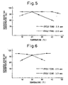
- Figures 5 and 6 show the other experimental results which were executed by using a fractionator shown in Figure 1.
- Figure 5 shows the change in oxygen concentration of the oxygen enhanced gas relative to the representative temperature detected by the temperature sensor 28, with 13X type zeolite filled in the columns 12.
- Figure 5 shows the operation with the cycle time of 2.0 sec provides better results than the operation with cycle time of 2.5 sec in the temperature range above 20 °C.
- Figure 6 is a graph similar to that of Figure 5, with 5A type zeolite filled in the columns 12.
- the operation with the cycle time of 2.5 sec acquires better results than the operation with cycle time of 2.0 sec in the temperature range above 20 °C.
- a fractionator 50 in Figure 7, includes a plurality of columns 52 for containing the adsorbent material the same as the first embodiment, top and bottom tanks 54 and 56 fluidly connected to the columns 52, a rotary distributor the same as the first embodiment shown in Figures 2 and 3 and a rotary mechanism or an AC motor 66 for rotating the rotary distributor.
- the top tank 54 is connected to a nasal mask put on a patient through first and second conduits 86 and 90 between which a humidifier 88 is provided.
- the first conduit 86 includes a flow adjustment valve 82 and a flow setter 84.
- the bottom tank 56 includes an air inlet port 58 and an exhaust port 60 through which nitrogen gas is discharged.
- the air inlet port 58 is fluidly connected to an air source or a blower 62 through an air conduit 64.
- the fractionator 50 further comprises a heating device for controlling the temperature of the columns 52.
- the heating device includes a fan 78 for generating a air flow, an air duct 80 for directing the air flow to the blower 62 for cooling the blower 62 and a flow controller or a damper 76 provided on the air duct 80 for controlling the air flow rate through the air duct 80.
- a controller 72 is provided for controlling the opening of the damper 76, based on the representative temperature detected by a temperature sensor 68 put on the side wall of one of the columns 52.
- the air flow directed to the blower 62 is heated by heat exchange with the blower 62.
- the duct 80 also directs the air flow from the blower 62 to the columns 52 to heat the columns 52.
- Figure 8 shows experimental results executed by using an experimental apparatus substantially the same as the second embodiment with 5A type zeolite, except that the heating device of the experimental apparatus is an electric heater which can heat the columns 52 up to a desired temperature.
- the vertical axis is the oxygen gas concentration in the produced oxygen enhanced gas
- the horizontal axis is the representative temperature.
- the oxygen concentration was measured with the side wall temperature set to a predetermined values.
- the oxygen gas concentration in the produced oxygen enhanced gas is not less than 90 % when the representative temperature detected by the sensor 68 is 20 - 60 °C, and it takes maximum value of 96 % when the representative temperature is around 40 °C.
- the controller 72 controls the opening of the damper 76 to maintain the representative temperature detected by the sensor 68 in the range 20 - 60 °C.
- the heating device utilizes the air flow used for cooling the blower 62 in Figure 7, the heating device can include an electric heater for maintaining the representative temperature of the side walls of the columns 52.
- the controller 72 controls the current supplied to the electric heater.
Landscapes
- Chemical & Material Sciences (AREA)
- Engineering & Computer Science (AREA)
- Analytical Chemistry (AREA)
- General Chemical & Material Sciences (AREA)
- Oil, Petroleum & Natural Gas (AREA)
- Chemical Kinetics & Catalysis (AREA)
- Separation Of Gases By Adsorption (AREA)
- Oxygen, Ozone, And Oxides In General (AREA)
Claims (3)
- Vorrichtung zum Erzeugen eines sauerstoffangereicherten Gases zur Verwendung in der Sauerstoffinhalationstherapie; umfassend:eine Luftquelle zum Zuführen von Luft;eine Mehrzahl von Säulen zum Aufnehmen eines Adsorptionsmaterials zum Adsorbieren von Stickstoffgas, wobei jede der Säulen ein erstes und ein zweites offenes Ende aufweist;Mittel zum Leiten der Luft von der Luftquelle zu der Säule durch das erste offene Ende der entsprechenden Säule;einen Tank für sauerstoffangereichertes Gas in Fließverbindung mit dem zweiten offenen Ende der entsprechenden Säule zum Empfangen von sauerstoffangereichertem Gas aus den Säulen;einen Schaltmechanismus, welcher benachbart zu den ersten offenen Enden der Säulen bereitgestellt ist, für ein sequentielles, selektives Umschalten zwischen Säulen, denen die Luft von der Luftquelle zugeführt wird, und Säulen, von denen der adsorbierte Stickstoff freigegeben wird zwecks Regeneration des Adsorptionsmaterials, so dass die entsprechenden Säulen wiederholt - gemäß einem Adsorptions-Regenerations-Zyklus - Stickstoffgas adsorbieren und das adsorbierte Stickstoffgas freigeben;einen Temperatursensor, verbunden mit einer Seitenwand einer der Säulen, zum Detektieren einer Temperatur, welche die Temperatur des Adsorptionsmaterials repräsentiert; undeine Steuereinheit zum Steuern des Adsorptions-Regenerations-Zyklus basierend auf der von dem Sensor detektierten repräsentativen Temperatur,dadurch gekennzeichnet, dassdas Adsorptionsmaterial ein Zeolith vom Typ 13X ist; unddie Steuereinheit den Adsorptions-Regenerations-Zyklus so steuert, dass die Zeit für die Adsorption des Stickstoffgases vermindert wird, wenn die repräsentative Temperatur nicht weniger als 20 °C beträgt.
- Vorrichtung zum Erzeugen eines sauerstoffangereicherten Gases zur Verwendung in der Sauerstoffinhalationstherapie; umfassend:eine Luftquelle zum Zuführen von Luft;eine Mehrzahl von Säulen zum Aufnehmen eines Adsorptionsmaterials zum Adsorbieren von Stickstoffgas, wobei jede der Säulen ein erstes und ein zweites offenes Ende aufweist;Mittel zum Leiten der Luft von der Luftquelle ins Innere der Säule durch das erste offene Ende der entsprechenden Säule;einen Tank für sauerstoffangereichertes Gas in Fließverbindung mit dem zweiten offenen Ende der entsprechenden Säule zum Empfangen von sauerstoffangereichertem Gas aus den Säulen;einen Schaltmechanismus, welcher benachbart zu den ersten offenen Enden der Säulen bereitgestellt ist, für ein sequentielles, selektives Umschalten zwischen Säulen, denen die Luft von der Luftquelle zugeführt wird, und Säulen, von denen der adsorbierte Stickstoff freigegeben wird zwecks Regeneration des Adsorptionsmaterials, so dass die entsprechenden Säulen wiederholt - gemäß einem Adsorptions-Regenerations-Zyklus - Stickstoffgas adsorbieren und das adsorbierte Stickstoffgas freigeben;einen mit einer Seitenwand einer der Säulen verbundenen Temperatursensor zum Detektieren einer Temperatur, welche die Temperatur des Adsorptionsmaterials repräsentiert; undeine Steuereinheit zum Steuern des Adsorptions-Regenerations-Zyklus basierend auf der von dem Sensor detektierten repräsentativen Temperatur,dadurch gekennzeichnet, dassdas Adsorptionsmaterial ein Zeolith vom Typ 5A ist; unddie Steuereinheit den Adsorptions-Regenerations-Zyklus so steuert, dass die Zeit für die Adsorption des Stickstoffgases vermindert wird, wenn die repräsentative Temperatur nicht mehr als 20 °C beträgt.
- Vorrichtung nach Anspruch 1 oder Anspruch 2, wobei der Schaltmechanismus umfasst: eine feststehende Scheibe, welche eine Mehrzahl von Öffnungen definiert, die entlang eines Kreises um das Zentrum der feststehenden Scheibe angeordnet sind, eine drehbare Scheibe, welche so angeordnet ist, dass sie mit einer Seite der feststehenden Scheibe in Kontakt steht, und einen Motor zum Drehen der drehbaren Scheibe;
wobei die drehbare Scheibe einen Einlasskanal in Fließverbindung mit der Luftquelle und einen Auslasskanal in Fließverbindung mit der Atmosphäre aufweist;
wobei jede der Säulen zu der zugehörigen Öffnung so angeordnet ist, dass eine Fließverbindung zwischen dem ersten offenen Ende und der korrespondierenden Öffnung bereitgestellt ist;
wobei die drehbare Scheibe gedreht wird, um den Einlass- und den Auslasskanal relativ zu den Öffnungen der feststehenden Scheibe zu bewegen, wobei der Einlass- und der Auslasskanal relativ zu den Öffnungen der feststehenden Scheibe sequentiell bewegt werden, um die Öffnung, die in Fließverbindung mit der Luftquelle steht, und die Öffnung, die in Fließverbindung mit der Atmosphäre steht, umzuschalten.
Applications Claiming Priority (4)
| Application Number | Priority Date | Filing Date | Title |
|---|---|---|---|
| JP11041481A JP2000237315A (ja) | 1999-02-19 | 1999-02-19 | 医療用圧力変動吸着型酸素濃縮装置 |
| JP4148299 | 1999-02-19 | ||
| JP4148199 | 1999-02-19 | ||
| JP04148299A JP4180721B2 (ja) | 1999-02-19 | 1999-02-19 | 圧力変動吸着型酸素濃縮装置 |
Publications (3)
| Publication Number | Publication Date |
|---|---|
| EP1029577A2 EP1029577A2 (de) | 2000-08-23 |
| EP1029577A3 EP1029577A3 (de) | 2002-11-06 |
| EP1029577B1 true EP1029577B1 (de) | 2006-04-26 |
Family
ID=26381107
Family Applications (1)
| Application Number | Title | Priority Date | Filing Date |
|---|---|---|---|
| EP00301276A Expired - Lifetime EP1029577B1 (de) | 1999-02-19 | 2000-02-18 | Vorrichtung zur Produktion von mit Sauerstoff angereichertem Gas aus Luft |
Country Status (3)
| Country | Link |
|---|---|
| US (1) | US6372026B1 (de) |
| EP (1) | EP1029577B1 (de) |
| DE (1) | DE60027493T2 (de) |
Families Citing this family (31)
| Publication number | Priority date | Publication date | Assignee | Title |
|---|---|---|---|---|
| US6551384B1 (en) * | 2001-07-05 | 2003-04-22 | Praxair Technology, Inc. | Medical oxygen concentrator |
| AU2003278594A1 (en) * | 2002-11-01 | 2004-05-25 | Pal Dharam | A new online service offering email, chat, people-location-in-a-dynamic-scenario, messaging, auctions and other services based upon real id of its subscribers |
| US7066985B2 (en) * | 2003-10-07 | 2006-06-27 | Inogen, Inc. | Portable gas fractionalization system |
| US20050072423A1 (en) | 2003-10-07 | 2005-04-07 | Deane Geoffrey Frank | Portable gas fractionalization system |
| US7438745B2 (en) * | 2003-10-07 | 2008-10-21 | Inogen, Inc. | Portable gas fractionalization system |
| US20050072426A1 (en) * | 2003-10-07 | 2005-04-07 | Deane Geoffrey Frank | Portable gas fractionalization system |
| US7135059B2 (en) | 2003-10-07 | 2006-11-14 | Inogen, Inc. | Portable gas fractionalization system |
| US7011693B2 (en) * | 2003-11-12 | 2006-03-14 | General Motors Corporation | Control of a hydrogen purifying pressure swing adsorption unit in fuel processor module for hydrogen generation |
| US7276107B2 (en) * | 2003-12-23 | 2007-10-02 | Praxair Technology, Inc. | Indexing rotary dual valve for pressure swing adsorption systems |
| US7402287B2 (en) * | 2004-12-17 | 2008-07-22 | Texaco Inc. | Apparatus and methods for producing hydrogen |
| US7354464B2 (en) * | 2004-12-17 | 2008-04-08 | Texaco Inc. | Apparatus and method for producing hydrogen |
| US7892304B2 (en) * | 2004-12-17 | 2011-02-22 | Texaco Inc. | Apparatus and method for controlling compressor motor speed in a hydrogen generator |
| US7354463B2 (en) * | 2004-12-17 | 2008-04-08 | Texaco Inc. | Apparatus and methods for producing hydrogen |
| US7954490B2 (en) | 2005-02-09 | 2011-06-07 | Vbox, Incorporated | Method of providing ambulatory oxygen |
| US7686870B1 (en) | 2005-12-29 | 2010-03-30 | Inogen, Inc. | Expandable product rate portable gas fractionalization system |
| US20090205493A1 (en) * | 2008-02-20 | 2009-08-20 | Thompson Loren M | Method of removing water from an inlet region of an oxygen generating system |
| US20090205494A1 (en) * | 2008-02-20 | 2009-08-20 | Mcclain Michael S | Single manifold assembly for oxygen-generating systems |
| US7722698B2 (en) * | 2008-02-21 | 2010-05-25 | Delphi Technologies, Inc. | Method of determining the purity of oxygen present in an oxygen-enriched gas produced from an oxygen delivery system |
| US20090211443A1 (en) * | 2008-02-21 | 2009-08-27 | Youngblood James H | Self-serviceable filter for an oxygen generating device |
| US20090214393A1 (en) * | 2008-02-22 | 2009-08-27 | Chekal Michael P | Method of generating an oxygen-enriched gas for a user |
| US8075676B2 (en) | 2008-02-22 | 2011-12-13 | Oxus America, Inc. | Damping apparatus for scroll compressors for oxygen-generating systems |
| US20090229460A1 (en) * | 2008-03-13 | 2009-09-17 | Mcclain Michael S | System for generating an oxygen-enriched gas |
| US8067646B2 (en) * | 2008-12-17 | 2011-11-29 | Uop Llc | Combined temperature controlled adsorption and heat pump process for fuel ethanol dehydration |
| US8936727B2 (en) * | 2009-03-06 | 2015-01-20 | Uop Llc | Multiple bed temperature controlled adsorption |
| US8226746B2 (en) * | 2008-12-17 | 2012-07-24 | Uop Llc | Indirectly heated temperature controlled adsorber for sorbate recovery |
| US8227648B2 (en) * | 2008-12-17 | 2012-07-24 | Uop Llc | Combined temperature controlled water adsorption and two stage heat pump process for fuel ethanol dehydration |
| EP2456541A4 (de) | 2009-07-22 | 2013-03-06 | Vbox Inc | Verfahren zur sauerstoffabtrennung und -verteilung |
| US7795479B1 (en) | 2009-12-15 | 2010-09-14 | Uop Llc | Temperature controlled adsorption multi-step regeneration cycle |
| CN106030295B (zh) | 2013-12-20 | 2019-10-01 | 皇家飞利浦有限公司 | 传感器系统和包括传感器系统的氧气分离器 |
| CN111545013B (zh) * | 2020-05-11 | 2022-03-18 | 杭州和利时自动化有限公司 | 一种变压吸附系统的控制方法及控制系统 |
| CN118437115B (zh) * | 2024-05-06 | 2024-10-29 | 江苏聚一邦环境科技有限公司 | 一种VOCs废气处理装置 |
Family Cites Families (21)
| Publication number | Priority date | Publication date | Assignee | Title |
|---|---|---|---|---|
| US3359706A (en) * | 1964-05-28 | 1967-12-26 | Mc Graw Edison Co | Adsorption gasd treating method and apparatus |
| US4026680A (en) * | 1974-10-30 | 1977-05-31 | Union Carbide Corporation | Air separation by adsorption |
| US4496376A (en) * | 1978-01-26 | 1985-01-29 | Litton Systems, Inc. | Variable area molecular sieve container having a thermal control system |
| US4197095A (en) * | 1978-08-31 | 1980-04-08 | Pall Corporation | Heatless adsorbent fractionators with microprocessor cycle control and process |
| US4194891A (en) * | 1978-12-27 | 1980-03-25 | Union Carbide Corporation | Multiple bed rapid pressure swing adsorption for oxygen |
| EP0046369B2 (de) * | 1980-08-18 | 1990-02-28 | Normalair-Garrett (Holdings) Limited | Molekularsieb-Gastrennungsverfahren |
| US4449990A (en) * | 1982-09-10 | 1984-05-22 | Invacare Respiratory Corp. | Method and apparatus for fractioning oxygen |
| US4455861A (en) * | 1983-01-24 | 1984-06-26 | Litton Systems, Inc. | Molecular sieve oxygen monitor |
| CA1297298C (en) * | 1986-09-22 | 1992-03-17 | Akira Kato | Oxygen enriching apparatus with means for regulating oxygen concentration of oxygen enriched gas |
| US4941894A (en) * | 1988-04-12 | 1990-07-17 | Hankison Division Of Hansen, Inc. | Gas drying or fractioning apparatus and method |
| US4925464A (en) * | 1988-11-17 | 1990-05-15 | Ryder International Corporation | Fluid flow switching valve assembly and system |
| US4927434A (en) * | 1988-12-16 | 1990-05-22 | Pall Corporation | Gas component extraction |
| USRE35099E (en) * | 1989-11-20 | 1995-11-28 | Sequal Technologies, Inc. | Fluid fractionator |
| WO1993016786A1 (en) | 1989-11-20 | 1993-09-02 | Hill Charles C | Improved fluid fractionator |
| US5114441A (en) * | 1990-11-02 | 1992-05-19 | Ryder International Corporation | Oxygen concentrator system and valve structure |
| US5425240A (en) * | 1992-10-01 | 1995-06-20 | The Boc Group, Inc. | Purification of oxygen by cryogenic adsorption |
| US5505825A (en) * | 1994-09-20 | 1996-04-09 | Foster Miller Inc. | Electrically conductive sorption system and method |
| US5593478A (en) * | 1994-09-28 | 1997-01-14 | Sequal Technologies, Inc. | Fluid fractionator |
| US5917135A (en) * | 1996-06-14 | 1999-06-29 | Invacare Corporation | Gas concentration sensor and control for oxygen concentrator utilizing gas concentration sensor |
| EP0853967A3 (de) * | 1997-01-21 | 1998-11-04 | The Boc Group, Inc. | Ventilvorrichtung für Gastrennung und Adsorptionssystem |
| FR2766384B1 (fr) * | 1997-07-25 | 1999-09-03 | Air Liquide | Regulation d'un procede psa |
-
2000
- 2000-02-18 EP EP00301276A patent/EP1029577B1/de not_active Expired - Lifetime
- 2000-02-18 DE DE60027493T patent/DE60027493T2/de not_active Expired - Lifetime
- 2000-02-22 US US09/510,154 patent/US6372026B1/en not_active Expired - Lifetime
Also Published As
| Publication number | Publication date |
|---|---|
| DE60027493D1 (de) | 2006-06-01 |
| DE60027493T2 (de) | 2006-12-07 |
| US6372026B1 (en) | 2002-04-16 |
| EP1029577A3 (de) | 2002-11-06 |
| EP1029577A2 (de) | 2000-08-23 |
Similar Documents
| Publication | Publication Date | Title |
|---|---|---|
| US6372026B1 (en) | Apparatus for producing oxygen enhanced gas from air | |
| EP1800731B1 (de) | Tragbarer medizinischer sauerstoffkonzentrator | |
| US5593478A (en) | Fluid fractionator | |
| EP2524715B1 (de) | Sauerstoffkonzentrator | |
| EP2822671B1 (de) | Vorrichtung und verfahren zum konzentrieren von gasen mittels adsorption | |
| WO2003004135A1 (en) | Medical oxygen concentrator | |
| JP2008110337A (ja) | 圧力スイング吸着の方法 | |
| JPH10113529A (ja) | ガス混合物の第1の成分をガス混合物の第2の成分から分離するための循環法 | |
| JPS60227813A (ja) | ガス混合物の吸着分離のための圧力揺動法 | |
| CN106731473A (zh) | 工业有机废气净化装置 | |
| JP4180721B2 (ja) | 圧力変動吸着型酸素濃縮装置 | |
| JPH0691127A (ja) | 吸着分離装置 | |
| KR100359274B1 (ko) | 의료용농축산소공급장치및그방법 | |
| CA2275685C (en) | Improved fluid fractionator | |
| JPH08210664A (ja) | 乾式除加湿装置 | |
| JP3333660B2 (ja) | 酸素濃縮装置 | |
| JP2000237315A (ja) | 医療用圧力変動吸着型酸素濃縮装置 | |
| JP2001104738A (ja) | 医療用酸素濃縮器 | |
| JPH03131504A (ja) | 酸素濃縮装置 | |
| KR102778659B1 (ko) | 고순도 중대형 산소 발생 장치 및 가습 장치 통합제어 시스템 | |
| CN206566700U (zh) | 工业有机废气净化装置 | |
| KR102588683B1 (ko) | 개방형 천장고를 구비한 실내 공간용 고순도 중대형 산소 발생 장치 및 가습 장치 통합제어 시스템 | |
| JP2915245B2 (ja) | 酸素濃縮装置 | |
| JP3003352B2 (ja) | 除加湿機 | |
| CN115342450B (zh) | 一种相变基除湿转轮装置及其应用方法 |
Legal Events
| Date | Code | Title | Description |
|---|---|---|---|
| PUAI | Public reference made under article 153(3) epc to a published international application that has entered the european phase |
Free format text: ORIGINAL CODE: 0009012 |
|
| AK | Designated contracting states |
Kind code of ref document: A2 Designated state(s): AT BE CH CY DE DK ES FI FR GB GR IE IT LI LU MC NL PT SE |
|
| AX | Request for extension of the european patent |
Free format text: AL;LT;LV;MK;RO;SI |
|
| PUAL | Search report despatched |
Free format text: ORIGINAL CODE: 0009013 |
|
| AK | Designated contracting states |
Kind code of ref document: A3 Designated state(s): AT BE CH CY DE DK ES FI FR GB GR IE IT LI LU MC NL PT SE |
|
| AX | Request for extension of the european patent |
Free format text: AL;LT;LV;MK;RO;SI |
|
| 17P | Request for examination filed |
Effective date: 20030409 |
|
| AKX | Designation fees paid |
Designated state(s): DE FR GB |
|
| 17Q | First examination report despatched |
Effective date: 20030909 |
|
| GRAP | Despatch of communication of intention to grant a patent |
Free format text: ORIGINAL CODE: EPIDOSNIGR1 |
|
| RAP1 | Party data changed (applicant data changed or rights of an application transferred) |
Owner name: TEIJIN LIMITED |
|
| GRAS | Grant fee paid |
Free format text: ORIGINAL CODE: EPIDOSNIGR3 |
|
| GRAA | (expected) grant |
Free format text: ORIGINAL CODE: 0009210 |
|
| AK | Designated contracting states |
Kind code of ref document: B1 Designated state(s): DE FR GB |
|
| REG | Reference to a national code |
Ref country code: GB Ref legal event code: FG4D |
|
| REF | Corresponds to: |
Ref document number: 60027493 Country of ref document: DE Date of ref document: 20060601 Kind code of ref document: P |
|
| ET | Fr: translation filed | ||
| PLBE | No opposition filed within time limit |
Free format text: ORIGINAL CODE: 0009261 |
|
| STAA | Information on the status of an ep patent application or granted ep patent |
Free format text: STATUS: NO OPPOSITION FILED WITHIN TIME LIMIT |
|
| 26N | No opposition filed |
Effective date: 20070129 |
|
| REG | Reference to a national code |
Ref country code: DE Ref legal event code: R082 Ref document number: 60027493 Country of ref document: DE Representative=s name: HOEGER, STELLRECHT & PARTNER PATENTANWAELTE MB, DE |
|
| REG | Reference to a national code |
Ref country code: FR Ref legal event code: PLFP Year of fee payment: 17 |
|
| REG | Reference to a national code |
Ref country code: FR Ref legal event code: PLFP Year of fee payment: 18 |
|
| PGFP | Annual fee paid to national office [announced via postgrant information from national office to epo] |
Ref country code: FR Payment date: 20170220 Year of fee payment: 18 Ref country code: DE Payment date: 20170209 Year of fee payment: 18 |
|
| PGFP | Annual fee paid to national office [announced via postgrant information from national office to epo] |
Ref country code: GB Payment date: 20170217 Year of fee payment: 18 |
|
| REG | Reference to a national code |
Ref country code: DE Ref legal event code: R119 Ref document number: 60027493 Country of ref document: DE |
|
| GBPC | Gb: european patent ceased through non-payment of renewal fee |
Effective date: 20180218 |
|
| REG | Reference to a national code |
Ref country code: FR Ref legal event code: ST Effective date: 20181031 |
|
| PG25 | Lapsed in a contracting state [announced via postgrant information from national office to epo] |
Ref country code: DE Free format text: LAPSE BECAUSE OF NON-PAYMENT OF DUE FEES Effective date: 20180901 |
|
| PG25 | Lapsed in a contracting state [announced via postgrant information from national office to epo] |
Ref country code: GB Free format text: LAPSE BECAUSE OF NON-PAYMENT OF DUE FEES Effective date: 20180218 Ref country code: FR Free format text: LAPSE BECAUSE OF NON-PAYMENT OF DUE FEES Effective date: 20180228 |