EP1029622A2 - Steinbohrer - Google Patents
Steinbohrer Download PDFInfo
- Publication number
- EP1029622A2 EP1029622A2 EP00102777A EP00102777A EP1029622A2 EP 1029622 A2 EP1029622 A2 EP 1029622A2 EP 00102777 A EP00102777 A EP 00102777A EP 00102777 A EP00102777 A EP 00102777A EP 1029622 A2 EP1029622 A2 EP 1029622A2
- Authority
- EP
- European Patent Office
- Prior art keywords
- hard metal
- tip
- metal plate
- stone drill
- drill according
- Prior art date
- Legal status (The legal status is an assumption and is not a legal conclusion. Google has not performed a legal analysis and makes no representation as to the accuracy of the status listed.)
- Granted
Links
Images
Classifications
-
- B—PERFORMING OPERATIONS; TRANSPORTING
- B23—MACHINE TOOLS; METAL-WORKING NOT OTHERWISE PROVIDED FOR
- B23B—TURNING; BORING
- B23B51/00—Tools for drilling machines
- B23B51/02—Twist drills
-
- E—FIXED CONSTRUCTIONS
- E21—EARTH OR ROCK DRILLING; MINING
- E21B—EARTH OR ROCK DRILLING; OBTAINING OIL, GAS, WATER, SOLUBLE OR MELTABLE MATERIALS OR A SLURRY OF MINERALS FROM WELLS
- E21B10/00—Drill bits
- E21B10/46—Drill bits characterised by wear resisting parts, e.g. diamond inserts
- E21B10/58—Chisel-type inserts
-
- B—PERFORMING OPERATIONS; TRANSPORTING
- B23—MACHINE TOOLS; METAL-WORKING NOT OTHERWISE PROVIDED FOR
- B23B—TURNING; BORING
- B23B2222/00—Materials of tools or workpieces composed of metals, alloys or metal matrices
- B23B2222/28—Details of hard metal, i.e. cemented carbide
-
- B—PERFORMING OPERATIONS; TRANSPORTING
- B23—MACHINE TOOLS; METAL-WORKING NOT OTHERWISE PROVIDED FOR
- B23B—TURNING; BORING
- B23B2226/00—Materials of tools or workpieces not comprising a metal
- B23B2226/75—Stone, rock or concrete
-
- B—PERFORMING OPERATIONS; TRANSPORTING
- B23—MACHINE TOOLS; METAL-WORKING NOT OTHERWISE PROVIDED FOR
- B23B—TURNING; BORING
- B23B2251/00—Details of tools for drilling machines
- B23B2251/18—Configuration of the drill point
-
- B—PERFORMING OPERATIONS; TRANSPORTING
- B23—MACHINE TOOLS; METAL-WORKING NOT OTHERWISE PROVIDED FOR
- B23B—TURNING; BORING
- B23B2251/00—Details of tools for drilling machines
- B23B2251/50—Drilling tools comprising cutting inserts
Definitions
- the invention relates to a stone drill according to the preamble of claim 1.
- Such a stone drill is, for example, from EP 0 761 927 A1 known.
- This drill has a hard metal plate provided that in a known manner across the Drill tip extends and is anchored there.
- This hard metal plate has a carbide tip that is opposite the protrudes oblique cutting surfaces of the hard metal plate. This is intended to better center the carbide drill be reached at the start of drilling.
- the cutting edge contour has already become known not let a hard metal plate ever run straight, but to make several wavy bends. Though is such a drill also suitable for hammer drills if an excessive protrusion is avoided. But arises with such a drill a longer lay line, so that the Surface pressure is reduced and the drilling progress accordingly is reduced. Such a drill has therefore become not enforced.
- the invention has for its object a stone drill according to the preamble of claim 1 to create the good drilling progress with a high drilling performance too shows when used in powerful hammer drills, without the wear being increased, although an improved one Centering performance should be given.
- the special Shape of the cutting edge contour of the hard metal plate has a centering function is given, but still the invention Stone drill insensitive also to the drilling of Pebble inclusions or the reinforcement in concrete.
- the Carbide tip is very good in the surrounding steel Supported drill so that even with strong lateral or oblique load there is no risk that the centering tip or carbide tip breaks off.
- the carbide tip is completely within the Envelope remains, that is, by turning the drill nowhere clamped cone of 130 degrees penetrates, and yet the carbide tip is pronounced, for example, with an acute angle of 90 degrees is.
- the rather small tip angle of the carbide tip leads to good centering, and retention the envelope not only leads to improved support, but in particular also to facilitate the Manufacture by using the existing forms for the feeding and handling of hard metal plates in the existing automatic assembly units can be used can.
- the constriction it is particularly favorable if the constriction the cutting edge contour around the carbide tip only in slightly extended and especially the radial length the constriction essentially the width of the Carbide tip corresponds.
- the configuration according to the invention surprisingly results the stone drill, a larger drilling progress always straight also when hitting the reinforcement in concrete. It is to assume that the hard metal plate according to the invention Reinforcement scratches with sharp edges so that they are next Impact of the hammer drill can be smashed more easily. The constriction apparently also removes the drilling dust improved.
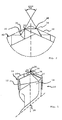
- the stone drill 10 shown in FIG. 1 has a hard metal plate 12, which in one in the drill tip 14 milled slot 16 is soldered.
- the hard metal plate according to the invention is special educated. It has a tip angle of 130 degrees, the apex angle forming an envelope 20, which at Rotation of the hard metal plate of secondary cutting edges 22, 24 and in the extension of this up to the axis 26 of the drill is swept over.
- the hard metal plate 12 has a hard metal tip 28, over which the main cutting edge 30 extends.
- the carbide tip is within envelope 20 according to the invention arranged, and completely such that the outer Ends 32, 34 of the main cutting edge 30 just the envelope curve 20 affect, but do not step through. This is better off Fig. 2 can be seen.
- constriction 36 Laterally next to the hard metal tip 28 is accordingly a constriction 36 is provided, the constriction 36 viewed in the axial direction over something more than that Width of the hard metal tip 28 extends. At their bottom points they have a radius 40 that is significantly less than the depth of the constriction, for example a third of the depth.
- the constriction is essentially symmetrical, the tip angle of the carbide tip 28 being about 90 degrees is, so that a good centering function is provided is, but still the cutting contour 42 by the constriction 36 is not significantly extended.
- the hard metal tip is 28 in a corresponding to the secondary cutting edges 22 and 24 Way of the surrounding drill tip 14, that is, there existing steel, supported.
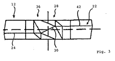
- FIG. 3 shows the manner in which the cutting edge 42 is performed.
- the cutting edge 42 has the axially viewed same course as a standard hard metal plate without constriction.
- the constriction is practically only only through two prismatic insert bodies in the sintered form formed for the hard metal plate, the design of which Fig. 3 can be seen.
- the width of the carbide tip is not based on the illustrated embodiment is limited.
- the width of the carbide tip is also preferably about 15% of the width of the hard metal plate amounts to vary. You can, for example, on a Third the width of the hard metal plate can be widened it is essential according to the invention that the hard metal tip remains within the envelope 20.
Landscapes
- Engineering & Computer Science (AREA)
- Geology (AREA)
- Mechanical Engineering (AREA)
- Life Sciences & Earth Sciences (AREA)
- Mining & Mineral Resources (AREA)
- General Life Sciences & Earth Sciences (AREA)
- Fluid Mechanics (AREA)
- Environmental & Geological Engineering (AREA)
- Physics & Mathematics (AREA)
- Geochemistry & Mineralogy (AREA)
- Processing Of Stones Or Stones Resemblance Materials (AREA)
- Drilling Tools (AREA)
- Earth Drilling (AREA)
- Steroid Compounds (AREA)
- Polishing Bodies And Polishing Tools (AREA)
Abstract
Description
- Fig. 1
- eine Seitenansicht eines erfindungsgemäßen Steinbohrers in einem Ausführungsbeispiel;
- Fig. 2
- eine vergrößerte Ansicht eines Teils der Ausführungsform gemäß Fig. 1; und
- Fig. 3
- eine Stirnansicht einer Hartmetallplatte für die Verwendung in einem Steinbohrer gemäß den Figuren 1 und 2.
Claims (8)
- Steinbohrer, mit einer Hartmetallplatte, die sich quer durch einen Schlitz in der Bohrerspitze erstreckt und dort verankert ist, wobei die Hartmetallplatte eine Hüllkurve mit einem Spitzenwinkel von etwa 130 Grad aufweist, und eine Hartmetallspitze aufweist, dadurch gekennzeichnet, daß die Hartmetallspitze (28) innerhalb der Hüllkurve (20) liegt und daß die Hauptschneide (13) und die Nebenschneiden (22, 24) einen kontinuierlichen Verlauf aufweisen.
- Steinbohrer nach Anspruch 1, dadurch gekennzeichnet, daß die Hartmetallspitze (28) einen Spitzenwinkel von deutlich weniger als 130 Grad, insbesondere von etwa 90 Grad, aufweist.
- Steinbohrer nach einem der vorhergehenden Ansprüche, dadurch gekennzeichnet, daß die Hartmetallspitze (28) eine Hauptschneide (30) der Hartmetallplatte (12) aufweist, die sich quer über die Hartmetallspitze (28) erstreckt.
- Steinbohrer nach einem der vorhergehenden Ansprüche, dadurch gekennzeichnet, daß die Hartmetallplatte (12) zur Hartmetallspitze (28) hin eine Einschnürung (36) aufweist, an welcher sie gegenüber der Hüllkurve (20) zurückspringt.
- Steinbohrer nach Anspruch 4, dadurch gekennzeichnet, daß die Einschnürung (36) eine in axialer Richtung weisende Kante und eine schräg nach aussen weisende Kante aufweist und der Übergang zwischen diesen durch einen Radius (40) gebildet ist, der deutlich kleiner als die Länge der beiden Kanten ist.
- Steinbohrer nach einem der vorhergehenden Ansprüche, dadurch gekennzeichnet, daß die Hartmetallplatte (12) sich etwa über die Hälfte ihrer radialen Länge in einem Spitzenwinkel von 130 Grad erstreckt und die Breite der Hartmetallspitze (28) zwischen 8 und 30% und insbesondere etwa 15% der Breite der Hartmetallplatte (12) beträgt.
- Steinbohrer nach einem der vorhergehenden Ansprüche, dadurch gekennzeichnet, daß die Hartmetallplatte (12) eine Schneidenkontur (42) aufweist, die gegenüber einer üblichen Hartmetallplatte (12) im Bereich einer Einschnürung (36) zurückspringt, wobei das Rücksprungmaß etwa ein Drittel der Breite der Hartmetallspitze (28) beträgt.
- Steinbohrer nach einem der vorhergehenden Ansprüche, dadurch gekennzeichnet, daß über den radialen Verlauf der Hartmetallplatte (12) lediglich eine Stufe vorgesehen ist, die die Einschnürung (36) bildet.
Applications Claiming Priority (2)
| Application Number | Priority Date | Filing Date | Title |
|---|---|---|---|
| DE29902665U DE29902665U1 (de) | 1999-02-15 | 1999-02-15 | Steinbohrer |
| DE29902665U | 1999-02-15 |
Publications (3)
| Publication Number | Publication Date |
|---|---|
| EP1029622A2 true EP1029622A2 (de) | 2000-08-23 |
| EP1029622A3 EP1029622A3 (de) | 2003-07-30 |
| EP1029622B1 EP1029622B1 (de) | 2006-08-23 |
Family
ID=8069414
Family Applications (1)
| Application Number | Title | Priority Date | Filing Date |
|---|---|---|---|
| EP00102777A Expired - Lifetime EP1029622B1 (de) | 1999-02-15 | 2000-02-10 | Steinbohrer |
Country Status (4)
| Country | Link |
|---|---|
| EP (1) | EP1029622B1 (de) |
| AT (1) | ATE337124T1 (de) |
| DE (2) | DE29902665U1 (de) |
| DK (1) | DK1029622T3 (de) |
Cited By (2)
| Publication number | Priority date | Publication date | Assignee | Title |
|---|---|---|---|---|
| DE10024433A1 (de) * | 2000-05-19 | 2001-11-29 | Hawera Probst Gmbh | Gesteinsbohrer |
| WO2007103093A3 (en) * | 2006-03-03 | 2007-11-08 | Illinois Tool Works | Masonry drill bit |
Family Cites Families (5)
| Publication number | Priority date | Publication date | Assignee | Title |
|---|---|---|---|---|
| DE1921677U (de) | 1965-05-18 | 1965-08-19 | Frank & Co Profilzieherei U Me | Profilwinkelleiste fuer kuchenmobel, kuehlschraenke, spinde od. dgl. |
| DE1921677B2 (de) * | 1969-04-28 | 1977-09-29 | Hilti Ag, Schaan (Liechtenstein) | Drehschlag-wendelbohrer |
| DE4442266A1 (de) | 1994-11-28 | 1996-05-30 | Hilti Ag | Werkzeug mit Trägerkörper und Schneidkörper |
| GB2303810A (en) * | 1995-07-29 | 1997-03-05 | Black & Decker Inc | Masonry drill bit |
| GB2318072A (en) * | 1996-09-21 | 1998-04-15 | Plansee Tizit Gmbh | Masonry bit |
-
1999
- 1999-02-15 DE DE29902665U patent/DE29902665U1/de not_active Expired - Lifetime
-
2000
- 2000-02-10 AT AT00102777T patent/ATE337124T1/de active
- 2000-02-10 DK DK00102777T patent/DK1029622T3/da active
- 2000-02-10 DE DE50013341T patent/DE50013341D1/de not_active Expired - Lifetime
- 2000-02-10 EP EP00102777A patent/EP1029622B1/de not_active Expired - Lifetime
Cited By (4)
| Publication number | Priority date | Publication date | Assignee | Title |
|---|---|---|---|---|
| DE10024433A1 (de) * | 2000-05-19 | 2001-11-29 | Hawera Probst Gmbh | Gesteinsbohrer |
| US6868924B2 (en) | 2000-05-19 | 2005-03-22 | Hawera Probst Gmbh | Rock drill |
| WO2007103093A3 (en) * | 2006-03-03 | 2007-11-08 | Illinois Tool Works | Masonry drill bit |
| US8157028B2 (en) | 2006-03-03 | 2012-04-17 | Illinois Tool Works Inc. | Masonry drill bit |
Also Published As
| Publication number | Publication date |
|---|---|
| ATE337124T1 (de) | 2006-09-15 |
| DE50013341D1 (de) | 2006-10-05 |
| DE29902665U1 (de) | 1999-04-29 |
| EP1029622B1 (de) | 2006-08-23 |
| EP1029622A3 (de) | 2003-07-30 |
| DK1029622T3 (da) | 2007-01-02 |
Similar Documents
| Publication | Publication Date | Title |
|---|---|---|
| EP2237913B1 (de) | Bohrwerkzeug mit ausspitzung | |
| EP0281997B1 (de) | Gesteinsbohrer | |
| DE3037097C2 (de) | Vollbohrwerkzeug, insbesondere Spiralbohrer | |
| DE4324411B4 (de) | Sägeblatt für das Metallschneiden | |
| DE69630842T2 (de) | Steinbohrer | |
| DE69630344T2 (de) | Walzgeschmiedeter Bohrer | |
| EP0657617B1 (de) | Gesteinsbohrer | |
| EP1302290B1 (de) | Bohrwerkzeug | |
| AT5577U1 (de) | Bohrer zum bohren von gestein | |
| EP1259699B1 (de) | Gesteinsbohrer | |
| DE102009049087B4 (de) | Bohrer | |
| EP0151251A2 (de) | Mehrschneidenbohrer | |
| DE2338726B2 (de) | Schneideinsatz | |
| DE3446004C2 (de) | Gesteinsbohrkrone | |
| EP1124662A1 (de) | Hartmetallschneidplatte für den einsatz an einem bohrer | |
| DE69614021T2 (de) | Spiralschaftfräser und dessen Herstellungsverfahren | |
| DE19942987A1 (de) | Bohrwerkzeug | |
| DE19734093A1 (de) | Gesteinsbohrer | |
| EP1455978A1 (de) | Schlag- oder hammerbohrer | |
| EP1029622B1 (de) | Steinbohrer | |
| EP1217165B1 (de) | Gesteinsbohrer | |
| DE10360707A1 (de) | Gesteinsbohrer | |
| DE10208630A1 (de) | Bohrwerkzeug | |
| EP1034864B1 (de) | Steinbohrer | |
| DE8303526U1 (de) | Spiralbohrer |
Legal Events
| Date | Code | Title | Description |
|---|---|---|---|
| PUAI | Public reference made under article 153(3) epc to a published international application that has entered the european phase |
Free format text: ORIGINAL CODE: 0009012 |
|
| AK | Designated contracting states |
Kind code of ref document: A2 Designated state(s): AT BE CH CY DE DK ES FI FR GB GR IE IT LI LU MC NL PT SE |
|
| AX | Request for extension of the european patent |
Free format text: AL;LT;LV;MK;RO;SI |
|
| PUAL | Search report despatched |
Free format text: ORIGINAL CODE: 0009013 |
|
| AK | Designated contracting states |
Designated state(s): AT BE CH CY DE DK ES FI FR GB GR IE IT LI LU MC NL PT SE |
|
| AX | Request for extension of the european patent |
Extension state: AL LT LV MK RO SI |
|
| 17P | Request for examination filed |
Effective date: 20031031 |
|
| 17Q | First examination report despatched |
Effective date: 20040301 |
|
| AKX | Designation fees paid |
Designated state(s): AT BE CH CY DE DK ES FI FR GB GR IE IT LI LU MC NL PT SE |
|
| GRAP | Despatch of communication of intention to grant a patent |
Free format text: ORIGINAL CODE: EPIDOSNIGR1 |
|
| GRAS | Grant fee paid |
Free format text: ORIGINAL CODE: EPIDOSNIGR3 |
|
| GRAA | (expected) grant |
Free format text: ORIGINAL CODE: 0009210 |
|
| AK | Designated contracting states |
Kind code of ref document: B1 Designated state(s): AT BE CH CY DE DK ES FI FR GB GR IE IT LI LU MC NL PT SE |
|
| PG25 | Lapsed in a contracting state [announced via postgrant information from national office to epo] |
Ref country code: IT Free format text: LAPSE BECAUSE OF FAILURE TO SUBMIT A TRANSLATION OF THE DESCRIPTION OR TO PAY THE FEE WITHIN THE PRESCRIBED TIME-LIMIT;WARNING: LAPSES OF ITALIAN PATENTS WITH EFFECTIVE DATE BEFORE 2007 MAY HAVE OCCURRED AT ANY TIME BEFORE 2007. THE CORRECT EFFECTIVE DATE MAY BE DIFFERENT FROM THE ONE RECORDED. Effective date: 20060823 Ref country code: NL Free format text: LAPSE BECAUSE OF FAILURE TO SUBMIT A TRANSLATION OF THE DESCRIPTION OR TO PAY THE FEE WITHIN THE PRESCRIBED TIME-LIMIT Effective date: 20060823 Ref country code: FI Free format text: LAPSE BECAUSE OF FAILURE TO SUBMIT A TRANSLATION OF THE DESCRIPTION OR TO PAY THE FEE WITHIN THE PRESCRIBED TIME-LIMIT Effective date: 20060823 Ref country code: IE Free format text: LAPSE BECAUSE OF FAILURE TO SUBMIT A TRANSLATION OF THE DESCRIPTION OR TO PAY THE FEE WITHIN THE PRESCRIBED TIME-LIMIT Effective date: 20060823 |
|
| REG | Reference to a national code |
Ref country code: GB Ref legal event code: FG4D Free format text: NOT ENGLISH |
|
| REG | Reference to a national code |
Ref country code: CH Ref legal event code: EP Ref country code: CH Ref legal event code: NV Representative=s name: KELLER & PARTNER PATENTANWAELTE AG |
|
| REG | Reference to a national code |
Ref country code: IE Ref legal event code: FG4D Free format text: LANGUAGE OF EP DOCUMENT: GERMAN |
|
| REF | Corresponds to: |
Ref document number: 50013341 Country of ref document: DE Date of ref document: 20061005 Kind code of ref document: P |
|
| PG25 | Lapsed in a contracting state [announced via postgrant information from national office to epo] |
Ref country code: SE Free format text: LAPSE BECAUSE OF FAILURE TO SUBMIT A TRANSLATION OF THE DESCRIPTION OR TO PAY THE FEE WITHIN THE PRESCRIBED TIME-LIMIT Effective date: 20061123 |
|
| PG25 | Lapsed in a contracting state [announced via postgrant information from national office to epo] |
Ref country code: ES Free format text: LAPSE BECAUSE OF FAILURE TO SUBMIT A TRANSLATION OF THE DESCRIPTION OR TO PAY THE FEE WITHIN THE PRESCRIBED TIME-LIMIT Effective date: 20061204 |
|
| REG | Reference to a national code |
Ref country code: DK Ref legal event code: T3 |
|
| PG25 | Lapsed in a contracting state [announced via postgrant information from national office to epo] |
Ref country code: PT Free format text: LAPSE BECAUSE OF FAILURE TO SUBMIT A TRANSLATION OF THE DESCRIPTION OR TO PAY THE FEE WITHIN THE PRESCRIBED TIME-LIMIT Effective date: 20070124 |
|
| NLV1 | Nl: lapsed or annulled due to failure to fulfill the requirements of art. 29p and 29m of the patents act | ||
| PG25 | Lapsed in a contracting state [announced via postgrant information from national office to epo] |
Ref country code: MC Free format text: LAPSE BECAUSE OF NON-PAYMENT OF DUE FEES Effective date: 20070228 |
|
| ET | Fr: translation filed | ||
| REG | Reference to a national code |
Ref country code: IE Ref legal event code: FD4D |
|
| PLBE | No opposition filed within time limit |
Free format text: ORIGINAL CODE: 0009261 |
|
| STAA | Information on the status of an ep patent application or granted ep patent |
Free format text: STATUS: NO OPPOSITION FILED WITHIN TIME LIMIT |
|
| 26N | No opposition filed |
Effective date: 20070524 |
|
| PGFP | Annual fee paid to national office [announced via postgrant information from national office to epo] |
Ref country code: BE Payment date: 20070727 Year of fee payment: 8 |
|
| PG25 | Lapsed in a contracting state [announced via postgrant information from national office to epo] |
Ref country code: GR Free format text: LAPSE BECAUSE OF FAILURE TO SUBMIT A TRANSLATION OF THE DESCRIPTION OR TO PAY THE FEE WITHIN THE PRESCRIBED TIME-LIMIT Effective date: 20061124 |
|
| BERE | Be: lapsed |
Owner name: DREBO WERKZEUGFABRIK G.M.B.H. Effective date: 20080228 |
|
| PG25 | Lapsed in a contracting state [announced via postgrant information from national office to epo] |
Ref country code: BE Free format text: LAPSE BECAUSE OF NON-PAYMENT OF DUE FEES Effective date: 20080228 |
|
| PG25 | Lapsed in a contracting state [announced via postgrant information from national office to epo] |
Ref country code: CY Free format text: LAPSE BECAUSE OF FAILURE TO SUBMIT A TRANSLATION OF THE DESCRIPTION OR TO PAY THE FEE WITHIN THE PRESCRIBED TIME-LIMIT Effective date: 20060823 |
|
| PGFP | Annual fee paid to national office [announced via postgrant information from national office to epo] |
Ref country code: DK Payment date: 20100222 Year of fee payment: 11 |
|
| PGFP | Annual fee paid to national office [announced via postgrant information from national office to epo] |
Ref country code: GB Payment date: 20100222 Year of fee payment: 11 |
|
| REG | Reference to a national code |
Ref country code: DK Ref legal event code: EBP |
|
| GBPC | Gb: european patent ceased through non-payment of renewal fee |
Effective date: 20110210 |
|
| PG25 | Lapsed in a contracting state [announced via postgrant information from national office to epo] |
Ref country code: GB Free format text: LAPSE BECAUSE OF NON-PAYMENT OF DUE FEES Effective date: 20110210 |
|
| PGFP | Annual fee paid to national office [announced via postgrant information from national office to epo] |
Ref country code: AT Payment date: 20120223 Year of fee payment: 13 |
|
| REG | Reference to a national code |
Ref country code: AT Ref legal event code: MM01 Ref document number: 337124 Country of ref document: AT Kind code of ref document: T Effective date: 20130228 |
|
| PG25 | Lapsed in a contracting state [announced via postgrant information from national office to epo] |
Ref country code: AT Free format text: LAPSE BECAUSE OF NON-PAYMENT OF DUE FEES Effective date: 20130228 |
|
| PGFP | Annual fee paid to national office [announced via postgrant information from national office to epo] |
Ref country code: CH Payment date: 20140123 Year of fee payment: 15 |
|
| PGFP | Annual fee paid to national office [announced via postgrant information from national office to epo] |
Ref country code: FR Payment date: 20140226 Year of fee payment: 15 |
|
| REG | Reference to a national code |
Ref country code: DE Ref legal event code: R231 Ref document number: 50013341 Country of ref document: DE |
|
| REG | Reference to a national code |
Ref country code: CH Ref legal event code: PCAR Free format text: NEW ADDRESS: EIGERSTRASSE 2 POSTFACH, 3000 BERN 14 (CH) |
|
| PG25 | Lapsed in a contracting state [announced via postgrant information from national office to epo] |
Ref country code: DE Free format text: LAPSE BECAUSE OF THE APPLICANT RENOUNCES Effective date: 20150304 |
|
| PGFP | Annual fee paid to national office [announced via postgrant information from national office to epo] |
Ref country code: LU Payment date: 20150302 Year of fee payment: 16 |
|
| REG | Reference to a national code |
Ref country code: CH Ref legal event code: PL |
|
| PG25 | Lapsed in a contracting state [announced via postgrant information from national office to epo] |
Ref country code: LI Free format text: LAPSE BECAUSE OF NON-PAYMENT OF DUE FEES Effective date: 20150228 Ref country code: CH Free format text: LAPSE BECAUSE OF NON-PAYMENT OF DUE FEES Effective date: 20150228 |
|
| REG | Reference to a national code |
Ref country code: FR Ref legal event code: ST Effective date: 20151030 |
|
| PG25 | Lapsed in a contracting state [announced via postgrant information from national office to epo] |
Ref country code: FR Free format text: LAPSE BECAUSE OF NON-PAYMENT OF DUE FEES Effective date: 20150302 |
|
| PG25 | Lapsed in a contracting state [announced via postgrant information from national office to epo] |
Ref country code: LU Free format text: LAPSE BECAUSE OF NON-PAYMENT OF DUE FEES Effective date: 20160210 |
|
| PGFP | Annual fee paid to national office [announced via postgrant information from national office to epo] |
Ref country code: DE Payment date: 20150225 Year of fee payment: 16 |