EP1029687A1 - Augmentation et réglage de densité de pixels avec des données minimales dans une imprimante incrémentale - Google Patents
Augmentation et réglage de densité de pixels avec des données minimales dans une imprimante incrémentale Download PDFInfo
- Publication number
- EP1029687A1 EP1029687A1 EP99110905A EP99110905A EP1029687A1 EP 1029687 A1 EP1029687 A1 EP 1029687A1 EP 99110905 A EP99110905 A EP 99110905A EP 99110905 A EP99110905 A EP 99110905A EP 1029687 A1 EP1029687 A1 EP 1029687A1
- Authority
- EP
- European Patent Office
- Prior art keywords
- colorant
- array
- data
- pixel
- pixels
- Prior art date
- Legal status (The legal status is an assumption and is not a legal conclusion. Google has not performed a legal analysis and makes no representation as to the accuracy of the status listed.)
- Granted
Links
Images




Classifications
-
- B—PERFORMING OPERATIONS; TRANSPORTING
- B41—PRINTING; LINING MACHINES; TYPEWRITERS; STAMPS
- B41J—TYPEWRITERS; SELECTIVE PRINTING MECHANISMS, i.e. MECHANISMS PRINTING OTHERWISE THAN FROM A FORME; CORRECTION OF TYPOGRAPHICAL ERRORS
- B41J2/00—Typewriters or selective printing mechanisms characterised by the printing or marking process for which they are designed
- B41J2/485—Typewriters or selective printing mechanisms characterised by the printing or marking process for which they are designed characterised by the process of building-up characters or image elements applicable to two or more kinds of printing or marking processes
- B41J2/505—Typewriters or selective printing mechanisms characterised by the printing or marking process for which they are designed characterised by the process of building-up characters or image elements applicable to two or more kinds of printing or marking processes from an assembly of identical printing elements
- B41J2/5056—Typewriters or selective printing mechanisms characterised by the printing or marking process for which they are designed characterised by the process of building-up characters or image elements applicable to two or more kinds of printing or marking processes from an assembly of identical printing elements using dot arrays providing selective dot disposition modes, e.g. different dot densities for high speed and high-quality printing, array line selections for multi-pass printing, or dot shifts for character inclination
- B41J2/5058—Typewriters or selective printing mechanisms characterised by the printing or marking process for which they are designed characterised by the process of building-up characters or image elements applicable to two or more kinds of printing or marking processes from an assembly of identical printing elements using dot arrays providing selective dot disposition modes, e.g. different dot densities for high speed and high-quality printing, array line selections for multi-pass printing, or dot shifts for character inclination locally, i.e. for single dots or for small areas of a character
-
- G—PHYSICS
- G06—COMPUTING OR CALCULATING; COUNTING
- G06K—GRAPHICAL DATA READING; PRESENTATION OF DATA; RECORD CARRIERS; HANDLING RECORD CARRIERS
- G06K15/00—Arrangements for producing a permanent visual presentation of the output data, e.g. computer output printers
- G06K15/02—Arrangements for producing a permanent visual presentation of the output data, e.g. computer output printers using printers
- G06K15/10—Arrangements for producing a permanent visual presentation of the output data, e.g. computer output printers using printers by matrix printers
- G06K15/102—Arrangements for producing a permanent visual presentation of the output data, e.g. computer output printers using printers by matrix printers using ink jet print heads
- G06K15/105—Multipass or interlaced printing
-
- G—PHYSICS
- G06—COMPUTING OR CALCULATING; COUNTING
- G06K—GRAPHICAL DATA READING; PRESENTATION OF DATA; RECORD CARRIERS; HANDLING RECORD CARRIERS
- G06K2215/00—Arrangements for producing a permanent visual presentation of the output data
- G06K2215/0002—Handling the output data
- G06K2215/0062—Handling the output data combining generic and host data, e.g. filling a raster
- G06K2215/0071—Post-treatment of the composed image, e.g. compression, rotation
-
- G—PHYSICS
- G06—COMPUTING OR CALCULATING; COUNTING
- G06K—GRAPHICAL DATA READING; PRESENTATION OF DATA; RECORD CARRIERS; HANDLING RECORD CARRIERS
- G06K2215/00—Arrangements for producing a permanent visual presentation of the output data
- G06K2215/0082—Architecture adapted for a particular function
- G06K2215/0094—Colour printing
Definitions
- This invention relates generally to machines and procedures for printing text or graphics on printing media such as paper, transparency stock, or other glossy media; and more particularly to a scanning machine and method that construct text or images from individual colorant spots created on a printing medium, in a two-dimensional pixel array.
- Thermal-inkjet printers and processes are of greatest interest; however the invention is applicable in other types of units such as, for example only, piezodriven inkjet printers and hot-wax transfer printers.
- a principal way to reproduce color tones is by varying the areal density, i. e. number per unit area, of such dots on the medium. This variation ranges from none (white, if the print medium is white) to full density.
- full density means that every location in the pixel array contains at least one dot. Making a color as intense as possible requires full density, to cover the printing medium with colorant.
- Another way to produce various color tones is to vary the density of the colorant itself, i. e. the concentration of the colored substance that makes up each dot. This can be done for instance by applying plural quanta of colorant at a common pixel location.
- quanta of colorant means the discrete units in which a printing system transmits colorant toward a printing medium. In inkjet and other liquid-ink systems, colorant quanta thus are drops of ink.
- Variation in color tones can also be accomplished by storing colorants at various concentrations within the printing mechanism, and using those colorants in printing. This approach is relatively more costly and is not taken up further in this document.
- Inkdrops for example vary in weight, volume, viscosity, cohesion, adhesion (including electronegativity and chemical affinities), pH, temperature, physical integrity (some drops break into pieces having various relationships), shape or shapes, dimensions, speed, and direction - as well as molecular weight, shape and dimensions - and all of these can affect resulting dot shape or size.
- dots are smaller than nominal, white spaces may appear in the areas where maximum color intensities should be, thus reducing such intensity through poor coverage.
- dots are larger than nominal, the associated excess colorant leads to oversaturation of the printing medium with colorant (particularly for colorant that is a liquid ink), which commonly creates undesirable image-quality defects.
- dots cannot simply be made too small (or too large) so as to be on the safe side. It is important that dot size be controlled as well as practical or cost-effective.
- dot-size selection is limited by the fact that positive variations produce oversaturation of colorant, again particularly for liquid ink.
- the native resolution of the system determines the dot size and in consequence the visibility of the individual dots - permitting only relatively little control over texture quality in highlight regions, as noted above.
- the first is that the distribution of dots in some analyzed uniform-intensity region of the image - i. e. , for some moderately large portion of the pixel grid - at fifty-percent input intensity (0.5 on the abscissa) is a simple alternating-pixels checkerboard pattern. With such a dot distribution, if the dots are all correctly positioned there is no overlap of dots anywhere in the image region.
- the lower quadrant of the graph shows an idealized but nearly realizable response (i. e. perceived intensity) to an idealized progression of input-data intensities.
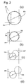
- the curve corresponds to placing drops of diameter d in a square pixel grid of pixel-size s (Fig. 2a), such that the diameter d just fits across the diagonal of the pixel.
- the dashed straight line 212 represents a fictitious case in which the colorant deposited in an overlapping area has just as much coloring power as if it were printed in two separate nonoverlapping spaces. In actuality the first-deposited colorant in those overlapping areas is muted by the overprinted additional colorant, so that its effect is substantially lessened.
- That dashed curve is not intended to represent actual performance quantitatively, but only to convey a general impression of the intensity response of such a system. In actuality the lower quadrant, too, of the response curve is idealized.
- dithering and other characteristics of a system typically do not permit filling in dots in an absolutely systematic fashion leading to a checkerboard pattern at fifty percent. Therefore in a real case some overlapping occurs even in the first quadrant and typically leads to a rolling-off of the curve well before the fifty-percent point.
- DPE dot-placement error
- Fig. 1b it is the entire graph, not only the lower-left quadrant, that shows an idealized but nearly realizable response. Because the pixel square is exactly circumscribed outside the dot circle, the dots if correctly positioned do not overlap at all, anywhere in the image region.
- the rectilinear idealized curve 221 spans the entire dynamic range of the printer.
- the problem - as seen based on geometry only - is not a knee but simply that the saturation is poor, and this plainly due to the large uncolored spaces in the corners 226 of all the pixels.
- Fig. 1b The same simplifying assumptions as for Fig. 1b are adopted here to show the response as rectilinear across the graph.
- dot size is fixed based on coverage and saturation for the colors of maximum intensity. Accordingly such an adjustment is very coarse, usually being limited to a selection between one dot or two, per colorant and pixel.
- C-Ret color resolution enhancement technology
- Each bit combination can be associated with a different number of colorant quanta, and the combinations need not be a direct binary representation of the number of quanta. For example “00” may represent no colorant, "01” and “10” may represent one quantum and two quanta respectively - but "11” may be used to represent four quanta or even five.
- the code establishes explicitly what quantities of quanta are to be provided; and the code as such is implemented directly.
- C-Ret controls the number of colorant quanta placed in each pixel.
- the size of an individual single-quantum isolated dot can be much smaller than the effective dot size of composite dots in high-density areas - i. e. , dots made from several individual colorant quanta.
- Such a system provides very small individual dots, less visible individually and so contributory to excellent print quality in highlights. At the same time it provides desired coverage and color intensity in regions of vivid color.
- This method allows for an adjustable maximum colorant amount by remapping, i. e. redefining, the number of colorant quanta (per location and per associated colorant type) that is respectively associated with each bit-value combination.
- C-Ret is thus capable of introducing into the system a nonlinearity that can be made opposite in effect to the undesired knee effects described above, and so can be made to compensate for such undesired effects.
- several passes or slower scan speed
- Such operation particularly including distribution of colorant application as among plural passes, is discussed in a later part of this "BACKGROUND" section.
- the C-Ret system has substantially the same drawback. If two data bits are used, the number of data bits is simply doubled at the outset - as compared with a conventional single-bit system operating with larger dots.
- Depletion-algorithm techniques avoid such risks and can accomplish the same results of controlling inking volume.
- Such procedures edit out colorant spots from the pixel-array pattern to be created on the printing medium - but system designers try to implement this in an inconspicuous way that interferes as little as possible with the desired appearance of the image.
- the present invention introduces such refinement.
- the present invention has several aspects or facets that can be used independently, although they are preferably employed together to optimize their benefits. Those facets are discussed in turn below.
- the invention is a method of printing an image, by construction from individual marks formed in a pixel array on a printing medium, based on pixels of a corresponding input data array.
- This method includes the step of applying all data for a particular colorant, in the input data array, one time to control deposition of the particular colorant in forming the pixel array on the printing medium.
- the method also includes the step of applying all data for the same particular colorant, in the data array, at least another time.
- This second application is to control deposition of an additional positive quantity of the same particular colorant in forming the pixel array on the printing medium.
- At least one of the applying steps includes the substep of selecting particular pixels of the data array to control deposition of the same particular colorant.
- this novel method enables printing of a fuller dynamic range of colorant density - without paying the data-bandwidth penalties previously supposed unavoidable. That is, the system can provide an extended density range with smaller data files to be stored, copied, and transmitted between different computers.
- the "pixel-array forming one time” include depositing colorant in one pass of the scanning printer; and the "pixel-array forming another time” include depositing colorant in another, different pass of the scanning printer.
- the selecting substep include defining a maximum density for the pixel array of the printing medium.
- the selecting substep include identifying locations of the particular pixels to receive said maximum density.
- the identifying include analyzing pixels of the data array to find locally dense areas. Further yet, it is desirable that this analyzing include counting neighboring pixels of at least some pixels in the data array.
- selecting substep include defining locations of the particular pixels to receive a particular colorant density for said particular colorant.
- selecting substep further include generation of additional density levels for printing based upon density levels within the data array; and that this generation include defining locations of specific pixels among the particular pixels, to receive at least one other specified colorant density for the same particular colorant.
- the method also include performing both applying steps with respect to at least one other particular colorant.
- the invention is a method of printing an image, by construction from individual colorant marks deposited in a pixel array on a printing medium, based on pixels of a corresponding original data array.
- the method includes the step of, based on the original array, defining an augmentation array.
- augmentation array means an array of selected pixels of the image that is to receive an additional positive quantity of colorant, beyond the quantity specified by the original data array. As the additional quantity is explicitly positive, this aspect of the present invention differs from depletion.
- the augmentation-array applying step increases the deposition of colorant, relative to the original-array applying step, by less than a one hundred percent increase. It will be noted that these first two stated preferences in essence reinforce the underlying concept of an "augmentation array" as set forth above.
- the applying step use the augmentation array to provide a nonlinear colorant-deposition response to the data array.
- this nonlinear colorant-deposition response tends to compensate for a nonlinear response - of the image-construction process - to the data array.
- the applying step include using the augmentation array to control operation of at least one pass of the printhead.
- the applying step use the augmentation array to control operation of at least one printhead.
- Yet another alternative preference - particularly for use with a printing mechanism that has plural sets of nozzles for a particular ink color and dilution - is that the applying step use the augmentation array to control operation of at least one set of nozzles.
- one way to implement this aspect of the invention is by directing to a printmasking stage (1) the original input data array, together with (2) the results of applying the augmentation array to the input data array.
- the printmasking function then distributes among plural printing passes all the pixels that make up the sum total of both data sets - analogously to the printmasking done in conventional systems such as plural-pass single-bit systems, C-Ret systems etc.
- This second facet of the invention is not limited to colorant augmentation in separate printing passes, but rather is also applicable to any method of controlling a portion of colorant deposition in forming the pixel array. Also possible, for instance, is selective increase of dot size for the pixels selected by the augmentation array.
- the invention is apparatus for printing an image on a printing medium, by construction from individual marks formed in a pixel array on a printing medium, based on pixels of a corresponding data array.
- the apparatus includes some means for analyzing pixels of the data array to identify areas of the data array that are locally dense.
- the apparatus includes some means for applying the identified locally dense areas of the data array to enhance printing of the image on the printing medium by adding colorant. Again for generality and breadth these means will be called the “applying means”.
- this third aspect of the invention complements those discussed earlier. It selects pixels for use as the augmentation array of the second aspect, in performing the dual data application of the first aspect.
- this third facet of the invention is practiced in conjunction with certain additional features or characteristics that maximize enjoyment of its benefits.
- the analyzing means operate by counting inked data-array pixels adjacent to at least some of the data-array pixels, and the applying means apply additional colorant to identified locally dense areas.
- the apparatus also include printhead devices for applying colorant, a carriage for moving those devices in a scan direction, printing-medium advance means providing relative motion between the carriage and medium at right angles to the scan direction, and an encoder system for developing carriage position and velocity signals;
- the analyzing means and applying means include a processor.
- the analyzing means and the applying means each operate with respect to each available particular colorant.
- This third facet of the invention is applicable to any method of controlling a portion of colorant deposition in forming the pixel array.
- this aspect of the invention is not limited to printing discrete colorant quanta in separate passes but rather - as described above for the second facet of the invention - can be implemented by dot-size increase if desired.
- an image is rendered with one bit per pixel-colorant combination, but this bitmap is used plural times.
- this bitmap is used plural times.
- the system produces composite dots, of a common colorant, at selected pixels that are -
- Performance of the present invention is very close to C-Ret, but the system is simpler and less expensive.
- this system refrains from augmentation at edges of lines, text and dense graphics. It thereby helps to preserve the sharpness of such features.
- propletion helps to avoid liquid saturation of the printing medium at high densities.
- the invention does so by selectively increasing the colorant-placement rate when demanding more intense colors - that is to say, by reserving high liquid loading for those particular situations in which high-intensity colors actually are needed for image quality.
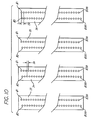
- Discrete pass control According to this approach, in one use the data are used to print the basic image, and in the other uses the same data are used to print additional colorant quanta on selected pixels.
- Slightly offset small dots 207, 209 can be implemented through a fractional-pixel-row advance, in either direction, following one or two passes for printing the main image data.
- Preferred embodiments for greater simplicity, select pixels to receive augmentation colorant in a discrete operation for that selection process, distinct from addressing pixels for the basic image. Selection preferably is done in this way, regardless of the timing of actual, physical application of colorant.
- colorant quanta developed as a result of C-Ret bits above binary "01" could be printed in respective separate passes.
- no such discrete-pass implementation of C-Ret is known to the present inventors.
- preferred embodiments of some facets of the invention are not limited to colorant augmentation in separate printing passes, but rather are also amenable to implementation by any method of controlling a portion of colorant deposition in forming the pixel array. Such methods for instance include selective increase of dot size, for the particular pixels selected by the augmentation array.
- Suitable compensation in timing may be provided to compensate for associated changes in inkdrop speed. As Wade suggests, such a method does demand care in monitoring or otherwise accounting for the effect on nearby nozzles, and attending to the stabilization of the overall printhead temperature.
- curve 215 has been drawn, arbitrarily, as adjusting the response to only about 90% of the full ideal response 212 mentioned earlier.
- the response to full input intensity can be pegged to virtually any desired value, including a value that makes the response function very nearly linear over the entire input-intensity range.
- the output-response range of the system can be redefined - in effect establishing a new scale 216 that spans the available output values from zero perceived response up to the selected new maximum value. That scale is then mapped to the operating byte range of numerical values, most commonly zero through two hundred fifty-five, used by the system microprocessors.
- Fig. 1a corresponds to the inscribed-pixel case of Fig. 2a.
- Generally analogous adjustments are shown to yield a response curve 222 for the circumscribed-pixel case of Fig. 2b, and here the curve has been shown drawn to the ideal maximum response - no remapping being required.
- the augmented-response curve has been constrained to raise the maximum output intensity by no more than that 49% increment.
- the constraint is by no means absolute, and augmentation arrays can be prepared to effect virtually any increment desired.
- Propletion is a broadly general invention, having as its main thrust the splitting and reinterpretation of physical data states - to enable a longer and more-stable dynamic range, with versatile control of the response transfer function. Accordingly propletion is amenable to much more highly elaborated implementations.
- One such refinement includes performing more than one augmentation usage of the original data.
- This variant may be practiced using the same augmentation arrays more than once, but with progressively more-stringent neighboring-pixel conditions (e. g. , neighbors present to more than one pixel distance, or present along diagonals as well as rank and file - or both).
- progressively more-stringent neighboring-pixel conditions e. g. , neighbors present to more than one pixel distance, or present along diagonals as well as rank and file - or both.
- different augmentation arrays can be provided for the higher-level propletion usage.
- Another implementation is a kind of melding of propletion with plural-bit systems such as C-Ret.
- the data format used may be for instance, double-bit - but the application of these data through propletion can then readily emulate the effects of a data system having many more bits, e. g. four or seven.
- a primary object of propletion is simply to make the most of the data that are stored, transmitted and processed, and this relative concept should not be misinterpreted to mean that an absolute minimum of data must be used.
- an accelerating or upward-concave propletion response contour 224 can be created to provide more punch than was ever present originally, in an image.
- This form of response too somewhat overemphasizing vivid colors, is highly prized - but in other quarters, as for instance in advertising materials or in popular reproductions of vivid, cheerful-appearing photos and the like for ornamental display.
- benign distortions of original dynamic range are easier to obtain than strictly linear reproduction.
- Fig. 13 An example of actual results in a very modest practical case appears as Fig. 13.
- the data relate to linearization and extension of a partially saturated intensity ramp for blue.
- the solid curve represents the ramp without, and the dashed curve with, propletion.
- the invention preferably uses two criteria. First, candidates are selected based upon density of the surrounding area, or in other words local density.
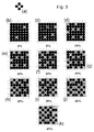
- Identification of dots that are in a locally dense area is accomplished by analyzing the neighbors of every pixel in the image. To do this the invention first overlays a so-called “candidate array” (Fig. 3a).
- a dot is a candidate for propletion - or for depletion - only if its four row-and-column neighbors exist.
- pixels are considered to belong to a dense area if they meet the logical criteria defined in that small array - namely, being surrounded by pixels at least horizontally and vertically.
- a dot is augmented if its position matches that of a gray dot in a so-called "augmentation array" (Figs. 3b through 3k) corresponding to a desired augmentation density.
- the system selects the desired density by choosing - either automatically or under manual control by a human operator - one of the ten available arrays.
- the chosen augmentation array defines both the maximum density of augmentation colorant and the locations of individual augmentation-colorant quanta to be printed. To implement these definitions, the system tiles the chosen augmentation array over the image in the manner of a conventional dither mask.
- the augmentation array is a simple binary mask, not a multiple-level threshold mask; and the augmentation array is used only in propletion, not in selecting pixels for printing the basic image.
- propletion and depletion can coexist even in a single document - applied, for instance, to different colors. If a candidate pixel is in the augmentation array, that pixel is propleted; and if not, it is instead depleted. The two functions can even coexist for the same color.
- Coexistence represents essentially a phase shift between data and final printed colorant. Such shifts may be appropriate because of environmental conditions such as humidity or temperature - interacting with the particular print medium in use - or due to geometry of features within the image.
- propletion processing can be performed in a separate procedure either before or after rendition.
- propletion can be used equally well with error diffusion instead of dithering.
- Performance of either the dither or diffusion procedure is included as part of rendition, in the conventional manner.
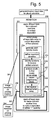
- the dither/diffusion process and the main propletion process, in the diagram, are rendition subblocks 231 and 232 - but either block may be propletion and the other may be the dither/diffusion process.
- pixel selection 233 the main propletion process in this printmasking form of the invention, as associated with the block 232 that contains the phrase "another time". In the diagram, however, pixel selection 233 is shown as straddling both rendition subblocks 231, 232.
- a primary function is generation 234 of additional density levels.
- This conceptual function most preferably includes two main practical steps as outlined earlier in subsection 1b, namely the definition 235 of maximum densities and identification 236 of locations to receive the augmentation colorant.
- the definition step 235 is preferably performed by selection of one of the augmentation arrays (Figs. 3b-3k). For perhaps optimum artistic fine control, an operator may do this manually by e. g. entering a selection into a computer application - for instance a printer driver or a stand-alone graphics/photopaint program.
- the operator who is not able or interested may opt out of that choice, simply designating (or allowing by default) the application program itself to perform the array selection.
- the system responds by doing so based upon usual preferences for ordinary or average image characteristics - or may be programmed to analyze aesthetic characteristics of the image to determine which augmentation array is most suitable.
- the identification step 236 includes analysis 237 of the data array to find locally dense areas and so pick out pixels that are candidates - for either propletion or depletion, as mentioned earlier. This step entails a counting 238 of pixels, using the candidate array (Fig. 3a).
- the identification 236 concludes with application 239 of the selected augmentation array to the candidates. If they are pixels shown in gray in the accompanying graphical representation of the augmentation array - as tiled over the image - then they are passed at 241 or 242 to the printmasking function 240; and if not, they are subjected to depletion (not shown).
- the printmask function 240 allocates among two or more printing passes all the dots to be printed, and those passes 251, 252 are then performed sequentially. Each printing pass contributes to reception 253 of the image on the printing medium.
- either the first or second step 331, 332 may be the propletion-processing step, and the remaining one of the two is then the conventional portion of the rendition.
- the principal propletion block 333 is drawn overlapping both of the main rendition steps 331, 332 and thus may be a portion of either.
- propletion processing may if desired actually be performed more than once - ordinarily at different augmentation density levels. Also some augmentation pixels may be selected in each of the two main rendition steps 331, 332 here (and in the printmasking variant as well).
- the preferred printer/plotter includes a main case 1 (Fig. 6) with a window 2, and a left-hand pod 3 that encloses one end of the chassis. Within that pod are carriage-support and -drive mechanics and one end of the printing-medium advance mechanism, as well as a pen-refill station containing supplemental ink cartridges.
- the printer/plotter also includes a printing-medium roll cover 4, and a receiving bin 5 for lengths or sheets of printing medium on which images have been formed, and which have been ejected from the machine.
- a bottom brace and storage shelf 6 spans the legs which support the two ends of the case 1.
- an entry slot 7 for receipt of continuous lengths of printing medium 4. Also included are a lever 8 for control of the gripping of the print medium by the machine.
- a front-panel display 11 and controls 12 are mounted in the skin of the right-hand pod 13. That pod encloses the right end of the carriage mechanics and of the medium advance mechanism, and also a printhead cleaning station. Near the bottom of the right-hand pod for readiest access is a standby switch 14.
- the carriage assembly 20 (Fig. 7) is driven in reciprocation by a motor 31 - along dual support and guide rails 32, 34 - through the intermediary of a drive belt 35.
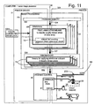
- the motor 31 is under the control of signals 57 from a digital electronic microprocessor (essentially all of Fig. 11 except the print engine 50).
- the carriage assembly 20 travels to the right 55 and left (not shown) while discharging ink 54.
- a very finely graduated encoder strip 33 is extended taut along the scanning path of the carriage assembly 20, and read by an automatic optoelectronic sensor 133, 233 to provide position and speed information 52 for the microprocessor. (In Fig. 11, signals in the print engine are flowing from left to right except the information 52 fed back from the encoder sensor 233 - as indicated by the associated leftward arrow.)
- the codestrip 33 thus enables formation of color inkdrops at ultrahigh resolution (typically 24 pixels/mm) and precision, during scanning of the carriage assembly 20 in each direction.
- a currently preferred location for the encoder strip 33 is near the rear of the carriage tray (remote from the space into which a user's hands are inserted for servicing of the pen refill cartridges).
- Immediately behind the pens is another advantageous position for the strip 36 (Fig. 3).
- the encoder sensor 133 (for use with the encoder strip in its forward position 33) or 233 (for rearward position 36) is disposed with its optical beam passing through orifices or transparent portions of a scale formed in the strip.
- Print medium 4A is thereby drawn out of the print-medium roll cover 4, passed under the pens on the carriage 20 to receive inkdrops 54 for formation of a desired image, and ejected into the print-medium bin 5.
- the carriage assembly 20 includes a previously mentioned rear tray 21 (Fig. 9) carrying various electronics. It also includes bays 22 for preferably four pens 23-26 holding ink of four different colors respectively - preferably cyan in the leftmost pen 23, then magenta 24, yellow 25 and black 26.
- Each of these pens particularly in a large-format printer/plotter as shown, preferably includes a respective ink-refill valve 27.
- the pens unlike those in earlier mixed-resolution printer systems, all are relatively long and all have nozzle spacing 29 (Fig. 10) equal to one-twelfth millimeter - along each of two parallel columns of nozzles. These two columns contain respectively the odd-numbered nozzles 1 to 299, and even-numbered nozzles 2 to 300.
- the two columns thus having a total of one hundred fifty nozzles each, are offset vertically by half the nozzle spacing, so that the effective pitch of each two-column nozzle array is approximately one-twenty-fourth millimeter.
- the natural resolution of the nozzle array in each pen is thereby made approximately twenty-four nozzles (yielding twenty-four pixels) per millimeter, or 600 per inch.
- black (or other monochrome) and color are treated identically as to speed and most other parameters.
- the number of printhead nozzles used is always two hundred forty, out of the three hundred nozzles (Fig. 10) in the pens.
- Alignment of the pens can be automatically checked and corrected through use of the extra nozzles.
- the invention is amenable to use with a very great variety in the number of nozzles actually operated.
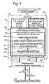
- Image-processing and printing-control tasks 332, 40 can be shared (Fig. 11) among one or more processors in each of the printer 320 and an associated computer and/or raster image processor 30.
- a raster image processor (“RIP") is nowadays often used to supplement or supplant the role of a computer or printer - or both - in the specialized and extremely processing-intensive work of preparing image data files for use, thereby releasing the printer and computer for other duties.
- processors in a computer or RIP typically operate a program known as a "printer driver”.
- processors may or may not include general-purpose multitasking digital electronic microprocessors (usually found in the computer 30) which run software, or general-purpose dedicated processors (usually found in the printer 320) which run firmware, or application-specific integrated circuits (ASICs, also usually in the printer).
- general-purpose multitasking digital electronic microprocessors usually found in the computer 30
- general-purpose dedicated processors usually found in the printer 320
- firmware or application-specific integrated circuits (ASICs, also usually in the printer.
- ASICs application-specific integrated circuits
- the system may be designed and constructed for performance of all data processing in one or another of the Fig. 11 modules - in particular, for example, the printer 320.
- the overall system typically includes a memory 232m for holding color-corrected image data.
- These data may be developed in the computer or raster image processor, for example with specific artistic input by an operator, or may be received from an external source.
- image memory 232m Ordinarily the input data proceed from image memory 232m to an image-processing stage 332 that includes some form of program memory 333 - whether card memory or hard drive and RAM, or ROM or EPROM, or ASIC structures.
- the memory 333 provides instructions 334, 335 for automatic operation of rendition 336 and printmasking 338.
- Image data cascades through these latter two stages 336, 338 in turn, resulting in new data 339 specifying the colorants to be deposited in each pixel, in each pass of the printhead carriage 20 over the printing medium 41. It remains for these data to be interpreted to form:
- the printing-control stage 40 necessarily contains electronics and program instructions for interpreting the colorant-per-pixel-per-pass information 339. Most of this electronics and programming is conventional, and represented in the drawing merely as a block 81 for driving the carriage and pen. That block in fact may be regarded as providing essentially all of the conventional operations of the printing control stage 40.
- the rendition stage preferably is replicated for each of the several system colorants CMYK as shown, and also preferably includes pixel-analyzing means 71 for identifying locally-dense areas of the data array.
- pixel-analyzing means 71 for identifying locally-dense areas of the data array.
- These means include some means 72 - ideally including the candidate array (Fig. 3a) - for counting adjacent inked data-array pixels as detailed earlier.
- the analyzing means 71 may be regarded as representative of various integrated-circuit stages (in addition to the pixel-analyzing means 71) devoted to performing the propletion functions discussed earlier. Outputs from the analyzing means 71 are used for depletion and propletion processing (not shown here) as discussed and illustrated earlier.
- the rendition stage also includes various other elements (not shown) for performing all of the conventional rendition functions, such as dithering or error diffusion.
- the printmasking apparatus 338 serves as additional-colorant application means 73 - also replicated for the several system colorants CMYK as shown - for completing the propletion functions.
- Output signals 339 from the printmasking stage flow to the printing-control module 40.
- There machine-language control signals are generated, based respectively on the several colorant data planes CMYK, developed in the rendition and printmask stages 336, 338 to operate each of the printheads 54.
- circuitry elements for an ASIC are not represented in schematics or other circuit diagrams as such, but rather in the form of Verilog HDL code, maintained in a computer for design purposes.
- HDL code represents both schematic and tooling.
Landscapes
- Engineering & Computer Science (AREA)
- Physics & Mathematics (AREA)
- Quality & Reliability (AREA)
- Mathematical Physics (AREA)
- General Engineering & Computer Science (AREA)
- General Physics & Mathematics (AREA)
- Theoretical Computer Science (AREA)
- Ink Jet (AREA)
- Ink Jet Recording Methods And Recording Media Thereof (AREA)
- Particle Formation And Scattering Control In Inkjet Printers (AREA)
- Color, Gradation (AREA)
Applications Claiming Priority (2)
| Application Number | Priority Date | Filing Date | Title |
|---|---|---|---|
| US09/252,163 US6690485B1 (en) | 1999-02-18 | 1999-02-18 | Pixel-density augmentation and adjustment with minimum data, in an incremental printer |
| US252163 | 1999-02-18 |
Publications (2)
| Publication Number | Publication Date |
|---|---|
| EP1029687A1 true EP1029687A1 (fr) | 2000-08-23 |
| EP1029687B1 EP1029687B1 (fr) | 2012-02-15 |
Family
ID=22954865
Family Applications (1)
| Application Number | Title | Priority Date | Filing Date |
|---|---|---|---|
| EP99110905A Expired - Lifetime EP1029687B1 (fr) | 1999-02-18 | 1999-06-02 | Augmentation et réglage de densité de pixels avec des données minimales dans une imprimante incrémentale |
Country Status (3)
| Country | Link |
|---|---|
| US (1) | US6690485B1 (fr) |
| EP (1) | EP1029687B1 (fr) |
| JP (1) | JP2000238255A (fr) |
Cited By (2)
| Publication number | Priority date | Publication date | Assignee | Title |
|---|---|---|---|---|
| EP1197916A3 (fr) * | 2000-10-13 | 2003-03-26 | Hewlett Packard Company, a Delaware Corporation | Appareil et méthode pour réduire des erreurs de déposition de colorant dans l'impression incrémentale |
| WO2020171817A1 (fr) * | 2019-02-21 | 2020-08-27 | Hewlett-Packard Development Company, L.P. | Compensation de la sursaturation due à un colorant enrichi en colorant |
Families Citing this family (11)
| Publication number | Priority date | Publication date | Assignee | Title |
|---|---|---|---|---|
| JP4134456B2 (ja) * | 1999-09-17 | 2008-08-20 | 富士ゼロックス株式会社 | 多色画像形成装置 |
| US6995863B1 (en) * | 2000-08-19 | 2006-02-07 | Hewlett-Packard Development Company, L.P. | Discretionary dotting for artifact control in incremental printing |
| US7190485B2 (en) * | 2001-06-14 | 2007-03-13 | Eastman Kodak Company | Method for multilevel printing of digital images using reduced colorant amounts |
| US7027185B2 (en) * | 2001-07-30 | 2006-04-11 | Hewlett-Packard Development Company, L.P. | Linearization of an incremental printer by measurements referred to a media-independent sensor calibration |
| US7023581B2 (en) * | 2001-07-30 | 2006-04-04 | Hewlett-Packard Development Company, L.P. | Compensating for drift and sensor proximity in a scanning sensor, in color calibrating incremental printers |
| US7548347B2 (en) * | 2002-08-28 | 2009-06-16 | Canon Kabushiki Kaisha | Image printing apparatus and image printing method |
| KR20050073192A (ko) * | 2004-01-09 | 2005-07-13 | 삼성전자주식회사 | 도트 라인 농도 조절 장치 및 방법 |
| JP2007015174A (ja) * | 2005-07-06 | 2007-01-25 | Canon Inc | 記録ヘッド及び記録装置 |
| US7817851B2 (en) * | 2006-11-27 | 2010-10-19 | Microsoft Corporation | Color fidelity metric |
| US8289568B1 (en) | 2009-02-19 | 2012-10-16 | Hewlett-Packard Development Company, L.P. | Printing using variable pixel-replication factors |
| US10063727B2 (en) * | 2015-12-29 | 2018-08-28 | Kabushiki Kaisha Toshiba | Marking apparatus and decoloring apparatus |
Citations (4)
| Publication number | Priority date | Publication date | Assignee | Title |
|---|---|---|---|---|
| EP0622204A2 (fr) | 1993-04-30 | 1994-11-02 | Hewlett-Packard Company | Commande auto-ajustable pour l'impression de la seconde page afin de réduire le maculage dans une imprimante par jet d'encre |
| EP0667241A1 (fr) * | 1990-05-11 | 1995-08-16 | Canon Kabushiki Kaisha | Appareil d'enregistrement avec lecteur de configuration de test |
| EP0741041A2 (fr) * | 1995-05-04 | 1996-11-06 | SCITEX DIGITAL PRINTING, Inc. | Technique de dispersion sélective de gouttelette |
| EP0881082A2 (fr) * | 1997-05-29 | 1998-12-02 | Xerox Corporation | Dispositif et procédé de formation d'images avec réduction des défauts d'impression |
Family Cites Families (3)
| Publication number | Priority date | Publication date | Assignee | Title |
|---|---|---|---|---|
| DE69331682T2 (de) * | 1993-01-08 | 2002-08-22 | Canon K.K., Tokio/Tokyo | Aufzeichnungsverfahren zur Gradationsaufzeichnung mit hell- und dunkelfarbigen Tinten und Gerät dafür |
| US5778160A (en) * | 1996-09-24 | 1998-07-07 | Xerox Corporation | Liquid ink printing system having region-dependent image processing |
| US6270187B1 (en) * | 1998-12-14 | 2001-08-07 | Hewlett-Packard Company | Method and apparatus for hiding errors in single-pass incremental printing |
-
1999
- 1999-02-18 US US09/252,163 patent/US6690485B1/en not_active Expired - Fee Related
- 1999-05-27 JP JP11148343A patent/JP2000238255A/ja active Pending
- 1999-06-02 EP EP99110905A patent/EP1029687B1/fr not_active Expired - Lifetime
Patent Citations (4)
| Publication number | Priority date | Publication date | Assignee | Title |
|---|---|---|---|---|
| EP0667241A1 (fr) * | 1990-05-11 | 1995-08-16 | Canon Kabushiki Kaisha | Appareil d'enregistrement avec lecteur de configuration de test |
| EP0622204A2 (fr) | 1993-04-30 | 1994-11-02 | Hewlett-Packard Company | Commande auto-ajustable pour l'impression de la seconde page afin de réduire le maculage dans une imprimante par jet d'encre |
| EP0741041A2 (fr) * | 1995-05-04 | 1996-11-06 | SCITEX DIGITAL PRINTING, Inc. | Technique de dispersion sélective de gouttelette |
| EP0881082A2 (fr) * | 1997-05-29 | 1998-12-02 | Xerox Corporation | Dispositif et procédé de formation d'images avec réduction des défauts d'impression |
Cited By (3)
| Publication number | Priority date | Publication date | Assignee | Title |
|---|---|---|---|---|
| EP1197916A3 (fr) * | 2000-10-13 | 2003-03-26 | Hewlett Packard Company, a Delaware Corporation | Appareil et méthode pour réduire des erreurs de déposition de colorant dans l'impression incrémentale |
| US7417768B1 (en) | 2000-10-13 | 2008-08-26 | Hewlett-Packard Development Company, L.P. | Apparatus and method for mitigating colorant-deposition errors in incremental printing |
| WO2020171817A1 (fr) * | 2019-02-21 | 2020-08-27 | Hewlett-Packard Development Company, L.P. | Compensation de la sursaturation due à un colorant enrichi en colorant |
Also Published As
| Publication number | Publication date |
|---|---|
| EP1029687B1 (fr) | 2012-02-15 |
| JP2000238255A (ja) | 2000-09-05 |
| US6690485B1 (en) | 2004-02-10 |
Similar Documents
| Publication | Publication Date | Title |
|---|---|---|
| KR100707603B1 (ko) | 양방향 잉크젯 프린터에서의 인쇄 방법 | |
| EP0863478B1 (fr) | Méthode et appareil pour l'impression à jet d'encre à passes multiples | |
| US7417768B1 (en) | Apparatus and method for mitigating colorant-deposition errors in incremental printing | |
| EP1029687B1 (fr) | Augmentation et réglage de densité de pixels avec des données minimales dans une imprimante incrémentale | |
| EP1225757B1 (fr) | Procédé et dispositif d'impression | |
| US6039434A (en) | Thresholded undercolor removal and black replacement in a thermal-inkjet printer or plotter | |
| EP1288002B1 (fr) | Procédé et appareil pour optimiser des volumes de gouttelettes séparés pour imprimantes multipoints à jet d'encre | |
| US7494204B2 (en) | Correction of paper feed error during interlace printing using a representative correction value | |
| EP1778496A2 (fr) | Moyens d'impression a jet d'encre a vitesse plus elevee | |
| US6799823B2 (en) | Removal or mitigation of artifacts in incremental printing | |
| EP1288003A1 (fr) | Imprimante à jet d'encre avec temps de séchage amélioré | |
| US6688726B2 (en) | System and method for producing print masks to eliminate step advance and swath height error banding | |
| EP0979734B1 (fr) | Procédé de correction de décalage des couleurs pour appareil d'impression par jet d'encre à passages multiples | |
| US6142605A (en) | Bidirectional color printing using multipass printmodes with at least partially swath-aligned inkjet printheads | |
| US6854828B2 (en) | Removal or mitigation of artifacts in composite-color incremental printing | |
| US6425699B1 (en) | Use of very small advances of printing medium for improved image quality in incremental printing | |
| JPH0885242A (ja) | インクジェット記録装置 | |
| EP1288001A1 (fr) | Procédé et dispositif pour l'augmentation du nombre de gradations d'impression disponible dans une imprimante à jet d'encre | |
| US20010038457A1 (en) | Method and device for processing a document available in the form of a set of digital data | |
| US6260948B1 (en) | Reducing granularity in highlights and yellow fields by plane-dependent tables, in device-state error diffusion | |
| EP1030264A2 (fr) | Impression incrémentale utilisant des masques | |
| JP7725291B2 (ja) | インクジェット記録装置及びインクジェット記録方法 | |
| US6851793B2 (en) | Very cost-effective incremental printing method and apparatus to directly reduce bidirectional hue shift | |
| JP4400162B2 (ja) | 印刷システム、コンピュータプログラム、及び、印刷方法 | |
| JP4736553B2 (ja) | インクジェット記録システム及び画像処理プログラム |
Legal Events
| Date | Code | Title | Description |
|---|---|---|---|
| PUAI | Public reference made under article 153(3) epc to a published international application that has entered the european phase |
Free format text: ORIGINAL CODE: 0009012 |
|
| AK | Designated contracting states |
Kind code of ref document: A1 Designated state(s): DE ES GB |
|
| AX | Request for extension of the european patent |
Free format text: AL;LT;LV;MK;RO;SI |
|
| 17P | Request for examination filed |
Effective date: 20010222 |
|
| RAP1 | Party data changed (applicant data changed or rights of an application transferred) |
Owner name: HEWLETT-PACKARD COMPANY, A DELAWARE CORPORATION |
|
| AKX | Designation fees paid |
Free format text: DE ES GB |
|
| 17Q | First examination report despatched |
Effective date: 20080218 |
|
| GRAP | Despatch of communication of intention to grant a patent |
Free format text: ORIGINAL CODE: EPIDOSNIGR1 |
|
| GRAS | Grant fee paid |
Free format text: ORIGINAL CODE: EPIDOSNIGR3 |
|
| RAP1 | Party data changed (applicant data changed or rights of an application transferred) |
Owner name: HEWLETT-PACKARD COMPANY |
|
| GRAA | (expected) grant |
Free format text: ORIGINAL CODE: 0009210 |
|
| RAP1 | Party data changed (applicant data changed or rights of an application transferred) |
Owner name: HEWLETT-PACKARD DEVELOPMENT COMPANY, L.P. |
|
| AK | Designated contracting states |
Kind code of ref document: B1 Designated state(s): DE ES GB |
|
| REG | Reference to a national code |
Ref country code: GB Ref legal event code: FG4D |
|
| REG | Reference to a national code |
Ref country code: DE Ref legal event code: R096 Ref document number: 69944041 Country of ref document: DE Effective date: 20120405 |
|
| PLBE | No opposition filed within time limit |
Free format text: ORIGINAL CODE: 0009261 |
|
| STAA | Information on the status of an ep patent application or granted ep patent |
Free format text: STATUS: NO OPPOSITION FILED WITHIN TIME LIMIT |
|
| 26N | No opposition filed |
Effective date: 20121116 |
|
| REG | Reference to a national code |
Ref country code: DE Ref legal event code: R097 Ref document number: 69944041 Country of ref document: DE Effective date: 20121116 |
|
| PG25 | Lapsed in a contracting state [announced via postgrant information from national office to epo] |
Ref country code: ES Free format text: LAPSE BECAUSE OF FAILURE TO SUBMIT A TRANSLATION OF THE DESCRIPTION OR TO PAY THE FEE WITHIN THE PRESCRIBED TIME-LIMIT Effective date: 20120526 |
|
| PGFP | Annual fee paid to national office [announced via postgrant information from national office to epo] |
Ref country code: GB Payment date: 20140527 Year of fee payment: 16 |
|
| PGFP | Annual fee paid to national office [announced via postgrant information from national office to epo] |
Ref country code: DE Payment date: 20140523 Year of fee payment: 16 |
|
| REG | Reference to a national code |
Ref country code: DE Ref legal event code: R119 Ref document number: 69944041 Country of ref document: DE |
|
| GBPC | Gb: european patent ceased through non-payment of renewal fee |
Effective date: 20150602 |
|
| PG25 | Lapsed in a contracting state [announced via postgrant information from national office to epo] |
Ref country code: DE Free format text: LAPSE BECAUSE OF NON-PAYMENT OF DUE FEES Effective date: 20160101 Ref country code: GB Free format text: LAPSE BECAUSE OF NON-PAYMENT OF DUE FEES Effective date: 20150602 |