EP1029692B9 - Appareil d'impression - Google Patents
Appareil d'impression Download PDFInfo
- Publication number
- EP1029692B9 EP1029692B9 EP99301170A EP99301170A EP1029692B9 EP 1029692 B9 EP1029692 B9 EP 1029692B9 EP 99301170 A EP99301170 A EP 99301170A EP 99301170 A EP99301170 A EP 99301170A EP 1029692 B9 EP1029692 B9 EP 1029692B9
- Authority
- EP
- European Patent Office
- Prior art keywords
- printhead
- sensor
- service station
- component
- distance
- Prior art date
- Legal status (The legal status is an assumption and is not a legal conclusion. Google has not performed a legal analysis and makes no representation as to the accuracy of the status listed.)
- Expired - Lifetime
Links
- 238000007639 printing Methods 0.000 title claims description 20
- 238000000034 method Methods 0.000 claims description 28
- 230000003287 optical effect Effects 0.000 claims description 26
- 230000008569 process Effects 0.000 claims description 12
- 238000012935 Averaging Methods 0.000 claims description 5
- 238000007641 inkjet printing Methods 0.000 claims description 4
- 230000000694 effects Effects 0.000 claims description 3
- 230000006870 function Effects 0.000 description 6
- 238000001514 detection method Methods 0.000 description 3
- 238000004364 calculation method Methods 0.000 description 2
- 238000010586 diagram Methods 0.000 description 2
- 239000000463 material Substances 0.000 description 2
- 229920001223 polyethylene glycol Polymers 0.000 description 2
- 208000000044 Amnesia Diseases 0.000 description 1
- 235000000391 Lepidium draba Nutrition 0.000 description 1
- 239000002202 Polyethylene glycol Substances 0.000 description 1
- 230000002411 adverse Effects 0.000 description 1
- 230000008901 benefit Effects 0.000 description 1
- 230000006866 deterioration Effects 0.000 description 1
- 238000006073 displacement reaction Methods 0.000 description 1
- 238000005516 engineering process Methods 0.000 description 1
- 238000000605 extraction Methods 0.000 description 1
- 238000010304 firing Methods 0.000 description 1
- 239000007788 liquid Substances 0.000 description 1
- 231100000863 loss of memory Toxicity 0.000 description 1
- 238000004519 manufacturing process Methods 0.000 description 1
- 239000003550 marker Substances 0.000 description 1
- 238000005259 measurement Methods 0.000 description 1
- 238000012986 modification Methods 0.000 description 1
- 230000004048 modification Effects 0.000 description 1
- 230000000877 morphologic effect Effects 0.000 description 1
- 238000010606 normalization Methods 0.000 description 1
- 229920003023 plastic Polymers 0.000 description 1
- 239000004033 plastic Substances 0.000 description 1
- 230000037452 priming Effects 0.000 description 1
- 230000002035 prolonged effect Effects 0.000 description 1
- 230000004044 response Effects 0.000 description 1
- 238000007790 scraping Methods 0.000 description 1
- 210000004894 snout Anatomy 0.000 description 1
Images

Classifications
-
- B—PERFORMING OPERATIONS; TRANSPORTING
- B41—PRINTING; LINING MACHINES; TYPEWRITERS; STAMPS
- B41J—TYPEWRITERS; SELECTIVE PRINTING MECHANISMS, i.e. MECHANISMS PRINTING OTHERWISE THAN FROM A FORME; CORRECTION OF TYPOGRAPHICAL ERRORS
- B41J2/00—Typewriters or selective printing mechanisms characterised by the printing or marking process for which they are designed
- B41J2/005—Typewriters or selective printing mechanisms characterised by the printing or marking process for which they are designed characterised by bringing liquid or particles selectively into contact with a printing material
- B41J2/01—Ink jet
- B41J2/135—Nozzles
- B41J2/165—Prevention or detection of nozzle clogging, e.g. cleaning, capping or moistening for nozzles
- B41J2/16505—Caps, spittoons or covers for cleaning or preventing drying out
- B41J2/16508—Caps, spittoons or covers for cleaning or preventing drying out connected with the printer frame
-
- B—PERFORMING OPERATIONS; TRANSPORTING
- B41—PRINTING; LINING MACHINES; TYPEWRITERS; STAMPS
- B41J—TYPEWRITERS; SELECTIVE PRINTING MECHANISMS, i.e. MECHANISMS PRINTING OTHERWISE THAN FROM A FORME; CORRECTION OF TYPOGRAPHICAL ERRORS
- B41J29/00—Details of, or accessories for, typewriters or selective printing mechanisms not otherwise provided for
- B41J29/38—Drives, motors, controls or automatic cut-off devices for the entire printing mechanism
- B41J29/393—Devices for controlling or analysing the entire machine ; Controlling or analysing mechanical parameters involving printing of test patterns
Definitions
- the present invention relates to determining the relative location of components of a printing apparatus, for example a large format printer.
- a printing apparatus for example a large format printer.
- inkjet printers having a printhead service station there is a need to accurately position the inkjet printheads relative to their respective service station cartridges.
- the service station is an essential subsystem in printers based on thermal inkjet technology (TIT). Its main purpose is to maintain optimal print quality and to do so, it can act on the printhead or pen in different ways (such as wiping, spitting). These actions are termed “servicing primitives”. They are arranged in complex sequences (servicing algorithms), that are executed in response to various triggers.
- TIT thermal inkjet technology
- a service station provides depend on the architecture, but as the printhead complexity increases, more and more sophisticated features need to be implemented. For instance, in the present printing apparatus there may be up to eight different “primitives”, namely: capping, spitting, wiping, PEG (i.e. the application of polyethylene glycol liquid), scraping, snout wiping, priming and drop detection. Since the volume occupied by the service station is much the same as in previous products and because more functionality has been added, there is less space available for each "primitive" .
- the servicing functions can work correctly with a maximum placement error of 0.8 millimetres for the scan axis.
- the service station axis substantially perpendicular to the scan axis is somewhat more tolerant accepting up to 1.5 millimetres.
- the mechanical tolerances alone, while meeting the goal in the service station axis are unacceptable for the scan axis (the worst-case placement error is 1.4 millimetres).
- An alternative is to calibrate the error out of the system. This determines the physical position of the components and adjusts each function based on this measurement.
- EP-A-0863009 discloses an optical encoding arrangement incorporating a marker for orientation on a service station carriage and a label for carrying information related to service station functions.
- the service station module may incorporate holes for storing and conveying information.
- the present invention seeks to overcome or reduce one or more of the above problems.
- a method of determining the relative location of a component of a printer apparatus with respect to a printhead carriage of the printer apparatus said component comprising one or more sub-units co-operating with a corresponding number of printheads on the carriage, wherein a sensor is used to determine the position of a reference location on said component relative to the sensor, characterised in that the sensor is also used to determine the position of at least one printhead relative to the sensor.
- a method of relatively locating at least one component of a printer apparatus to a printhead mounted on a printer carriage wherein an optical sensor mounted on the carriage is used to scan a reference location on the component, characterised in that there is also determined the relative location of the optical sensor to the printhead on the printer carriage.
- the sensor is preferably an optical sensor and, to determine the relative location of the optical sensor to the printhead (K), the printhead is caused to print during a carriage movement a reference mark extending substantially in the direction of the media axis, and the optical sensor subsequently scans the reference mark along the scan axis and there is determined therefrom the sensor to printhead distance ("j") in the direction of the scan axis.
- the reference mark is preferably a straight line.
- the step of determining the sensor to printhead distance (j) is preceded by causing the printhead (K) to print a reference mark in the direction of the scan axis, then using the optical sensor to scan the reference mark along the media axis of the printing apparatus, and then determining the sensor to printhead distance (r) in the direction of the media axis and taking into account its effect on the determination of the sensor to printhead distance (j) in the direction of the scan axis.
- the reference mark extending in the direction of the scan axis is also preferably a straight line.
- the components may be one or more service station insert members mounted in a service station.
- the insert members are preferably cartridges which perform various servicing functions and may each be associated with a respective printhead.
- an inkjet printing apparatus comprising one or more printheads mounted on a printer carriage and means for determining the position of at least one other component of the printing apparatus relative to the or each printhead, said determining means comprising a sensor mounted on the printer carriage, characterised in that calibration means are provided which determine the relative positions of the sensor and the or each printhead.
- the sensor is preferably an optical sensor.
- the component(s) may be one or more respective service station insert members mounted in a service station, the sensor being an optical sensor, means being provided which define one or more reference locations within the service station area, the reference locations being optically detectable by the optical sensor, and the or each reference location being provided on a respective service station insert member.
- each reference location is constituted by a through hole in a part of the respective service station insert member, e.g. in its handle or lid.
- each service station insert member has a respective reference location. These locations may be averaged to reduce any residual errors.
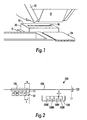
- Fig. 1 shows a prior art arrangement illustrating the type of location system used in Hewlett-Packard Designjet printers in the 2000 and 2500 series.
- Fig. 1 corresponds to Fig. 13 of the previously-mentioned pending U.S. patent application 09/031115.
- An optical sensor 17 including a light emitting diode and a photocell (not shown) is mounted on a printer carriage 10.
- a service station housing 24 is of black plastics material and has a mount section 71 for an insert section 70 which is of white material for the purposes of contrast.
- Section 70 has a white top surface 75 which defines a rectangular slot 76 to constitute a reference mark which is traversed by the sensor 17 to locate its position relative to the printer carriage 10.
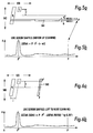
- Figs. 2 and 3 show front and top plan views of a printing apparatus 100 in accordance with the present invention.
- printer carriage 110 mounted on printer carriage 110 are a black printhead or pen K, three colour printheads C, M and Y, e.g. cyan, magenta and yellow, and a line sensor 117 incorporating a light-emitting diode and a photocell.
- the end 111 of carriage defines its position along the scan axis 120, which has a point of origin at a right bump position 122.
- Also illustrated in Fig. 2 are a "LED to K" distance "j” and a "carriage edge to K" distance "q” along the scan axis.
- a service station 130 is located adjacent to one end of the carriage scan axis and comprises four respective service station insert members.
- the insert members are manufactured independently and subsequently inserted in the service station housing.
- the insert members are preferably service station cartridges incorporating four printhead cleaners 130C, 130M, 130Y, 130K, corresponding to the four colour printheads.
- each cleaner lid has a handle or grip portion 131 which includes a through hole or slot 132 adjacent to and at a predetermined distance from one end of portion 131.
- a label 133 which is originally blank but is subsequently inked to represent use of the printing apparatus.
- the label may incorporate information in written and/or coded form indicating the appropriate type of ink.
- each printhead is spaced transversely to the scan axis, and because the printer carriage 110 moves continuously during printing, it is known to angle the printheads C, M, Y, K by a small angle of 1.79° relative to the true perpendicular direction, and this is shown in exaggerated fashion in the top plan view of Fig. 3.
- the printhead cleaners are also slanted at the same angle so that the paper movement axis 140 is at 1.79° to the so-called service station axis 142.
- Fig. 3 also indicates a "LED to K" distance "r" (distance between centres) along the paper axis. Both Figs. 2 and 3 also indicate a reference hole 132 to printhead cleaner centre distance "s”.
- Fig. 4 is a view corresponding to Fig. 2 but with the printheads C, M, Y and K in their capped disposition, with carriage edge 111 in its "capping position".
- the purpose of the calibration process is to ensure that each printhead is aligned as accurately as possible with the centre of its corresponding cleaner.
- the calibration process comprises the following steps:
- the printer needs to ascertain the optimum gain and LED type for the particular printing medium type which is loaded. This is accomplished by LED calibration by printing a black box 150, Fig. 8 on an inserted paper sheet 155, and then scanning over the black box and the adjacent white area. In practice, box 150 is printed solidly in black ink. The line sensor control block then modifies its internal parameters to work optimally in this range.
- step c) of the process involves the printing of a line in the direction of the scan axis. Since such a pattern is very sensitive to "nozzles out" (a nozzle out at the boundary produces an error of one dot), step b) involves facilitating the avoidance of such an error.
- the drop detector is calibrated and a drop detection process is then performed to look for a group of 32 consecutive working nozzles. This information is used subsequently when drawing the line in the direction of the scan axis.
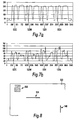
- Sensor 117 then scans (with bottom-up scanning) along the paper axis 140, to produce the sample shown in Fig. 5 b , and the distance "r" from the line sensor to the K printhead is then determined, taking into account which 32 nozzles were used.
- a reference mark in the form of a black line 146, Figs. 6 a and 8, is drawn, by firing the K printhead during a carriage movement.
- the line 146 extends substantially in the direction of the media axis, in this case substantially vertically. As explained above, this pattern will actually have a slant of 1.79°.
- lines 144 and 146 are printed solidly in black ink.
- the line sensor 117 is then scanned over the portions 131 of the printhead cleaners, typically obtaining a waveform as shown in Fig. 7 a for new printhead cleaners.
- the small "bumps" at the extreme left and right of the waveform represent the edges of the service station housing.
- the waveform in between represents features of the service station cartridges, and in particular, from the left, the vertical lines represent respectively:
- the scanning process includes the following steps:
- Fig. 7b indicates a waveform corresponding to Fig. 7a but of a dirty printhead cleaner, e.g. after a prolonged period of use. Despite general deterioration of the waveform because of ink covering portions 131, the locations of the through holes 132 are still distinct because they provide a sharper contrast.
- the position relative to the K printhead can be calculated simply by adding the LED to K printhead distance "j".
- the centre positions of the other three cartridges 130C, 130M and 130Y are also taken into account by means of a suitable averaging process. In this way, the effect of any misalignment of these other cartridges is minimized, and a satisfactory capping of all printheads can occur. Accuracy of positioning with less than ⁇ 0.7mm of error is obtained.
- the above-described calibration process typically occurs only once during the lifetime of a printer. If the printheads or the service station cartridges are replaced, they usually remain within satisfactory tolerances. However, should there be a loss of memory, or should the entire service station housing need replacing, for example, then the control system is configured so that a service engineer may use the process to recalibrate the positions of the printer components.
- the above-described arrangement has the advantage of reducing tolerance problems in two ways, namely calibrating the position of the service station cartridges 130 themselves, rather than the housing, and also taking into account the actual "LED to K" distance "j".
- Using holes 132 in the cartridges provides accurate location thereof, and taking into account the location of all four cartridges 130. and then averaging their displacements from a nominal position, reduces any residual errors in positioning for the capping process.
- the capping function of the service station is the one requiring the tightest tolerance and so the capping region is the best region to locate the calibration holes 132.
- the thus-determined capping position serves as a reference for the rest of the servicing "primitives".
- the calibrated part of the service station cartridge may be other than the capping position.
- a hole or other reference marking on the service station housing could be used, as in the prior art. This still gives an improved positioning accuracy, since the distance "j" is more accurately determined than allowed previously by the tolerance of the mechanical housing. Indeed, the reference location may be on a component of the printer other than the service station. For example, the precise determination of "j" can be used in the printhead alignment process to accurately place the line sensor 117 over narrow patterns. It can also be used to allow the calculation of the real position of the media margins, which is crucial for the media loader.
- the value of "j" may be taken as a preset value, in which case the improved calibration results from the determination of the actual positions of one or more of the printhead cleaner cartridges.
- the scan axis and media axis have other orientations, e.g. vertical and horizontal respectively.
Landscapes
- Ink Jet (AREA)
- Common Mechanisms (AREA)
Claims (17)
- Procédé pour déterminer l'emplacement relatif d'un composant (130) d'un appareil d'imprimante (100) par rapport à un chariot de tête d'impression (110) de l'appareil d'imprimante, ledit composant comprenant un ou plusieurs sous-ensembles (130C, 130M, 130Y, 130K) coopérant avec un nombre correspondant de têtes d'impression (C, M, Y, K) sur le chariot (110), dans lequel un capteur (117) est utilisé pour déterminer la position d'un emplacement de référence (132) sur ledit composant par rapport au capteur (117), caractérisé en ce que le capteur (117) est aussi utilisé pour déterminer la position d'au moins une tête d'impression par rapport au capteur.
- Procédé pour déterminer l'emplacement relatif d'au moins un composant (130) d'un appareil imprimant (100) par rapport à une tête d'impression (K) montée sur un chariot d'imprimante (110), dans lequel un capteur optique (117) monté sur le chariot (110) est utilisé pour balayer un emplacement de référence (132) sur le composant (130), caractérisé en ce qu'il est aussi déterminé l'emplacement relatif du capteur optique (117) par rapport à la tête d'impression (K) sur le chariot d'imprimante.
- Procédé selon la revendication 1 ou 2, dans lequel il est d'abord déterminé la distance entre le capteur et la tête d'impression (j) dans la direction de l'axe de balayage ou la distance entre le capteur et la tête d'impression (r) dans la direction de l'axe médian et ensuite il est déterminé l'autre (r, j) desdites distances.
- Procédé selon la revendication 3, dans lequel le capteur est un capteur optique (117) et, pour déterminer l'emplacement relatif du capteur optique par rapport à la tête d'impression (K), la tête d'impression est amenée à imprimer, durant un mouvement du chariot, une marque de référence (146) se prolongeant sensiblement dans la direction de l'axe médian, et le capteur optique (117) par la suite balaye la marque de référence le long de l'axe de balayage (120) et à partir de ceci il est déterminé la distance entre le capteur et la tête d'impression (« j ») dans la direction de l'axe de balayage.
- Procédé selon la revendication 4, dans lequel l'étape de détermination de la distance entre le capteur et la tête d'impression (j) est précédée par le fait d'amener la tête d'impression (K) à imprimer une marque de référence (144) dans la direction de l'axe de balayage, ensuite le fait d'utiliser le capteur optique (117) pour balayer la marque de référence (144) le long de l'axe médian (140) de l'appareil imprimant, et ensuite les faits de déterminer la distance entre le capteur et la tête d'impression (r) dans la direction de l'axe médian et de prendre en compte son effet sur la détermination de la distance entre le capteur et la tête d'impression (j) dans la direction de l'axe de balayage.
- Procédé selon la revendication 5, dans lequel la marque de référence (144) dans la direction de l'axe de balayage est imprimée par un groupe sélectionné de jets contigus de la tête d'impression (K) et dans lequel, avant d'imprimer la marque de référence (144), une vérification est faite pour un groupe de taille appropriée de jets en état de marche, la distance (h) dudit groupe par rapport au centre de la tête d'impression étant prise en compte durant le calcul de la distance entre le capteur et la tête d'impression (r) dans la direction de l'axe médian.
- Procédé selon une revendication précédente quelconque, dans lequel l'emplacement de référence (132) est constitué par un trou débouchant.
- Procédé selon une revendication précédente quelconque, dans lequel le capteur (117) balaye une pluralité d'emplacements de référence (132C, 132M, 132Y, 132K) respectivement sur des sous-ensembles mutuellement associés (130C, 130M, 130Y, 130K) dudit composant (130) et les résultats sont sujets à un processus de calcul de moyenne.
- Procédé selon la revendication 8, dans lequel les sous-ensembles associés mutuellement sont les nettoyeurs de têtes d'impression (130C, 130M, 130Y, 130K) d'une unité d'entretien d'imprimante (130).
- Procédé selon la revendication 2, dans lequel le(s) composant(s) est/sont un ou plusieurs éléments d'insertion d'unité d'entretien (130C, 130M, 130Y, 130K) montés dans une unité d'entretien (130).
- Procédé selon la revendication 10, dans lequel le capteur détecte les emplacements de références agencés sur ceux respectifs desdits éléments d'insertion de l'unité d'entretien et la moyenne des résultats est faite.
- Procédé d'exploitation d'un appareil imprimant dans lequel, pour coordonner la co-opération des sous-ensembles (C, M, Y, K) d'un premier composant avec les sous-ensembles respectifs (130C, 130M, 130Y, 130K) d'un deuxième composant (130), il est réalisé une étape de détermination d'emplacement relatif selon une revendication précédente quelconque.
- Appareil imprimant à jet d'encre (100) comprenant une ou plusieurs têtes d'impression (C, M, Y, K) montées sur un chariot d'imprimante (110) et un moyen pour déterminer la position d'au moins un autre composant (130) de l'appareil imprimant par rapport à la ou chaque tête d'impression, ledit moyen de détermination comprenant un capteur (117) monté sur le chariot d'imprimante (110), caractérisé en ce que des moyens de calibrage sont fournis qui déterminent les positions relatives du capteur (117) et de la ou chaque tête d'impression.
- Appareil imprimant à jet d'encre selon la revendication 13, dans lequel le capteur est un capteur optique (117) et l'autre dit composant est un élément d'insertion de nettoyeur de tête d'impression (130K) d'une unité d'entretien d'imprimante (130) et ayant un trou débouchant (132) se trouvant dans une partie de celui-ci qui est détecté par le capteur optique.
- Appareil imprimant à jet d'encre (100) selon la revendication 13, dans lequel ledit composant est au moins un élément d'insertion de nettoyeur de tête d'impression (130C, 130M, 130Y, 130K) monté sur une unité d'entretien (130), le capteur est un capteur optique (117), il est fourni des moyens définissant un ou plusieurs emplacements de référence à l'intérieur de la zone d'unité d'entretien, les emplacements de référence étant détectables optiquement par le capteur optique (117), et le ou chaque emplacement de référence (132C, 132M, 132Y, 132K) est fourni sur un élément d'insertion d'unité d'entretien.
- Appareil imprimant selon la revendication 15, dans lequel le ou chaque emplacement de référence est constitué par un trou débouchant (132) se trouvant dans une partie (131) de son élément d'insertion d'unité d'entretien respectif (130K).
- Appareil imprimant selon la revendication 15 ou 16, dans lequel chaque élément d'insertion d'unité d'entretien (130C, 130M, 130Y, 130K) a un emplacement de référence respectif (132C, 132M, 132Y, 132K) et des moyens sont fournis pour faire une moyenne des résultats pour une pluralité d'emplacements de référence et prendre en compte le résultat moyen durant la détermination d'une distance entre la tête d'impression et l'élément d'insertion d'unité d'entretien.
Priority Applications (4)
| Application Number | Priority Date | Filing Date | Title |
|---|---|---|---|
| DE69907397T DE69907397T2 (de) | 1999-02-17 | 1999-02-17 | Druckvorrichtung |
| EP99301170A EP1029692B9 (fr) | 1999-02-17 | 1999-02-17 | Appareil d'impression |
| JP2000036745A JP2001038981A (ja) | 1999-02-17 | 2000-02-15 | 相対位置決定方法 |
| US09/506,151 US6568787B1 (en) | 1999-02-17 | 2000-02-17 | Apparatus and method for accurately positioning inkjet printheads |
Applications Claiming Priority (1)
| Application Number | Priority Date | Filing Date | Title |
|---|---|---|---|
| EP99301170A EP1029692B9 (fr) | 1999-02-17 | 1999-02-17 | Appareil d'impression |
Publications (3)
| Publication Number | Publication Date |
|---|---|
| EP1029692A1 EP1029692A1 (fr) | 2000-08-23 |
| EP1029692B1 EP1029692B1 (fr) | 2003-05-02 |
| EP1029692B9 true EP1029692B9 (fr) | 2003-12-03 |
Family
ID=8241227
Family Applications (1)
| Application Number | Title | Priority Date | Filing Date |
|---|---|---|---|
| EP99301170A Expired - Lifetime EP1029692B9 (fr) | 1999-02-17 | 1999-02-17 | Appareil d'impression |
Country Status (4)
| Country | Link |
|---|---|
| US (1) | US6568787B1 (fr) |
| EP (1) | EP1029692B9 (fr) |
| JP (1) | JP2001038981A (fr) |
| DE (1) | DE69907397T2 (fr) |
Families Citing this family (28)
| Publication number | Priority date | Publication date | Assignee | Title |
|---|---|---|---|---|
| US6411324B1 (en) * | 2000-10-18 | 2002-06-25 | Hewlett-Packard Company | Edge to edge printing method and apparatus for printers |
| GB2379413A (en) * | 2001-09-10 | 2003-03-12 | Seiko Epson Corp | Printhead alignment method |
| US6834853B2 (en) * | 2002-11-18 | 2004-12-28 | Hewlett-Packard Development Company, Lp | Multi-pass deskew method and apparatus |
| US20050073539A1 (en) * | 2003-10-07 | 2005-04-07 | Mcgarry Mark | Ink placement adjustment |
| US8241905B2 (en) | 2004-02-24 | 2012-08-14 | The Curators Of The University Of Missouri | Self-assembling cell aggregates and methods of making engineered tissue using the same |
| US7273262B2 (en) | 2004-06-23 | 2007-09-25 | Hewlett-Packard Development Company, L.P. | System with alignment information |
| US20070263026A1 (en) * | 2006-04-29 | 2007-11-15 | Quanyuan Shang | Methods and apparatus for maintaining inkjet print heads using parking structures |
| US20070252863A1 (en) * | 2006-04-29 | 2007-11-01 | Lizhong Sun | Methods and apparatus for maintaining inkjet print heads using parking structures with spray mechanisms |
| US20070256709A1 (en) * | 2006-04-29 | 2007-11-08 | Quanyuan Shang | Methods and apparatus for operating an inkjet printing system |
| US7607752B2 (en) * | 2006-11-17 | 2009-10-27 | Hewlett-Packard Development Company, L.P. | Misfiring print nozzle compensation |
| US7703873B2 (en) * | 2007-03-15 | 2010-04-27 | Hewlett-Packard Development Company, L.P. | Method and apparatus for image registration |
| JP5624981B2 (ja) | 2008-06-24 | 2014-11-12 | ザ・キュレーターズ・オブ・ザ・ユニバーシティ・オブ・ミズーリThe Curators Ofthe University Of Missouri | 自己集合性多細胞体、および前記多細胞体を用いて3次元の生物構造体を作製する方法 |
| AU2011318437B2 (en) * | 2010-10-21 | 2015-02-26 | Organovo, Inc. | Devices, systems, and methods for the fabrication of tissue |
| HK1200483A1 (en) | 2011-09-12 | 2015-08-07 | 奥加诺沃公司 | Engineered tissues for in vitro research uses, arrays thereof, and methods of making the same |
| AU2011265415A1 (en) | 2011-12-21 | 2013-07-11 | Canon Kabushiki Kaisha | Real-time linefeed measurement of inkjet printer |
| US9499779B2 (en) | 2012-04-20 | 2016-11-22 | Organovo, Inc. | Devices, systems, and methods for the fabrication of tissue utilizing UV cross-linking |
| US9442105B2 (en) | 2013-03-15 | 2016-09-13 | Organovo, Inc. | Engineered liver tissues, arrays thereof, and methods of making the same |
| SG11201600770RA (en) | 2013-07-31 | 2016-02-26 | Organovo Inc | Automated devices, systems, and methods for the fabrication of tissue |
| EP3808838B1 (fr) | 2014-04-04 | 2024-04-10 | Organovo, Inc. | Tissu mammaire tridimensionnel artificiel, tissu adipeux, et modèle de maladies tumorales |
| JP2016034725A (ja) * | 2014-08-01 | 2016-03-17 | 東芝テック株式会社 | ラベルプリンタおよびラベルプリンタの制御方法 |
| KR20170064547A (ko) | 2014-10-06 | 2017-06-09 | 오가노보, 인크. | 조작된 신장 조직, 이의 어레이, 및 이를 제조하는 방법 |
| EP3213501B1 (fr) * | 2014-10-30 | 2019-12-25 | Hewlett-Packard Development Company, L.P. | Configuration d'un système d'imagerie |
| US11529436B2 (en) | 2014-11-05 | 2022-12-20 | Organovo, Inc. | Engineered three-dimensional skin tissues, arrays thereof, and methods of making the same |
| WO2017083402A1 (fr) | 2015-11-09 | 2017-05-18 | Organovo, Inc. | Procédés améliorés de fabrication de tissus |
| KR20190077407A (ko) | 2016-11-10 | 2019-07-03 | 오가노보, 인크. | 바이오프린팅된 모발 모낭 및 그의 용도 |
| US11117378B2 (en) | 2017-05-01 | 2021-09-14 | Hewlett-Packard Development Company, L.P. | Guide bar determination |
| WO2020117273A1 (fr) | 2018-12-07 | 2020-06-11 | Hewlett-Packard Development Company, L.P. | Ensemble de maintenance de tête d'impression |
| WO2021236065A1 (fr) * | 2020-05-19 | 2021-11-25 | Hewlett-Packard Development Company, L.P. | Stations de recouvrement dotées de mécanismes de positionnement |
Family Cites Families (6)
| Publication number | Priority date | Publication date | Assignee | Title |
|---|---|---|---|---|
| US3111598A (en) | 1960-08-31 | 1963-11-19 | Gen Dynamics Corp | Matrix for a character display tube |
| US5289208A (en) * | 1991-10-31 | 1994-02-22 | Hewlett-Packard Company | Automatic print cartridge alignment sensor system |
| US5404020A (en) * | 1993-04-30 | 1995-04-04 | Hewlett-Packard Company | Phase plate design for aligning multiple inkjet cartridges by scanning a reference pattern |
| US5397192A (en) * | 1993-11-01 | 1995-03-14 | Hewlett-Packard Company | Shuttle-type printers and methods for operating same |
| US5835108A (en) * | 1996-09-25 | 1998-11-10 | Hewlett-Packard Company | Calibration technique for mis-directed inkjet printhead nozzles |
| US6076913A (en) | 1997-03-04 | 2000-06-20 | Hewlett-Packard Company | Optical encoding of printhead service module |
-
1999
- 1999-02-17 EP EP99301170A patent/EP1029692B9/fr not_active Expired - Lifetime
- 1999-02-17 DE DE69907397T patent/DE69907397T2/de not_active Expired - Fee Related
-
2000
- 2000-02-15 JP JP2000036745A patent/JP2001038981A/ja not_active Withdrawn
- 2000-02-17 US US09/506,151 patent/US6568787B1/en not_active Expired - Fee Related
Also Published As
| Publication number | Publication date |
|---|---|
| JP2001038981A (ja) | 2001-02-13 |
| DE69907397T2 (de) | 2004-01-22 |
| EP1029692A1 (fr) | 2000-08-23 |
| DE69907397D1 (de) | 2003-06-05 |
| US6568787B1 (en) | 2003-05-27 |
| EP1029692B1 (fr) | 2003-05-02 |
Similar Documents
| Publication | Publication Date | Title |
|---|---|---|
| EP1029692B9 (fr) | Appareil d'impression | |
| EP0775587B1 (fr) | Alignement d'une tête d'impression à jet d'encre par la mesure d'erreurs et une mémoire de données | |
| EP0622220B1 (fr) | Alignement d'une cartouche à jet d'encre multiple pour une impression bidirectionnelle par balayage d'un élément de référence | |
| US6572213B2 (en) | System and method for detecting invisible ink drops | |
| EP1245399B1 (fr) | Méthode d'alignement améliorée pour dispositif d'impression et appareil correspondant | |
| JP3514508B2 (ja) | インクジェット・カートリッジの整列用基準パターン | |
| US6164750A (en) | Automated test pattern technique using accelerated sequence of color printing and optical scanning | |
| EP1889722B1 (fr) | Imprimante à jet d'encre de type réseau et procédé pour déterminer la condition de ses buses | |
| US8523310B2 (en) | Printing apparatus and printing method | |
| EP1176802A2 (fr) | Techniques pour mesurer la position des repères sur médias et pour aligner des dispositifs à jet d'encre | |
| US8424988B2 (en) | Recording apparatus and recording position adjustment method | |
| JP5848978B2 (ja) | 人間観察に知覚されにくいテストパターン、およびインクジェットプリンタのテストパターンに対応する画像データの分析方法 | |
| US20120169810A1 (en) | Printing apparatus and adjustment pattern printing method | |
| US7787145B2 (en) | Methods for improving print quality in a hand-held printer | |
| KR20070120902A (ko) | 기록 장치 및 반송 방법 | |
| JPH071725A (ja) | インクジェット・カートリッジの整列用装置 | |
| US7044573B2 (en) | Printhead alignment test pattern and method for determining printhead misalignment | |
| US6164753A (en) | Optical sensor system to calibrate a printhead servicing location in an inkjet printer | |
| JP2014061599A (ja) | 記録装置及びレジストレーション調整値の取得方法 | |
| JP4756842B2 (ja) | プリント位置調整方法およびプリント装置 | |
| US20080079766A1 (en) | Correction value determining method, correction value determining apparatus, and storage medium having program stored thereon | |
| JP2012504060A (ja) | マーク付け要素の位置合わせ | |
| JP6552276B2 (ja) | 記録装置および記録位置調整方法 | |
| US12263679B2 (en) | Droplet deposition apparatus and methods for determining misalignment thereof | |
| JPH06340065A (ja) | インクジェット・カートリッジの整列方法 |
Legal Events
| Date | Code | Title | Description |
|---|---|---|---|
| PUAI | Public reference made under article 153(3) epc to a published international application that has entered the european phase |
Free format text: ORIGINAL CODE: 0009012 |
|
| AK | Designated contracting states |
Kind code of ref document: A1 Designated state(s): DE GB NL |
|
| AX | Request for extension of the european patent |
Free format text: AL;LT;LV;MK;RO;SI |
|
| 17P | Request for examination filed |
Effective date: 20001218 |
|
| RAP1 | Party data changed (applicant data changed or rights of an application transferred) |
Owner name: HEWLETT-PACKARD COMPANY, A DELAWARE CORPORATION |
|
| 17Q | First examination report despatched |
Effective date: 20010326 |
|
| AKX | Designation fees paid |
Free format text: DE GB NL |
|
| GRAH | Despatch of communication of intention to grant a patent |
Free format text: ORIGINAL CODE: EPIDOS IGRA |
|
| GRAH | Despatch of communication of intention to grant a patent |
Free format text: ORIGINAL CODE: EPIDOS IGRA |
|
| GRAA | (expected) grant |
Free format text: ORIGINAL CODE: 0009210 |
|
| RIN1 | Information on inventor provided before grant (corrected) |
Inventor name: MURCIA, ANTONI Inventor name: TAYLOR, CHRIS Inventor name: BRUCH, XAVIER Inventor name: GIRONES, XAVIER |
|
| AK | Designated contracting states |
Designated state(s): DE GB NL |
|
| REG | Reference to a national code |
Ref country code: GB Ref legal event code: FG4D |
|
| REF | Corresponds to: |
Ref document number: 69907397 Country of ref document: DE Date of ref document: 20030605 Kind code of ref document: P |
|
| PLBE | No opposition filed within time limit |
Free format text: ORIGINAL CODE: 0009261 |
|
| STAA | Information on the status of an ep patent application or granted ep patent |
Free format text: STATUS: NO OPPOSITION FILED WITHIN TIME LIMIT |
|
| 26N | No opposition filed |
Effective date: 20040203 |
|
| PGFP | Annual fee paid to national office [announced via postgrant information from national office to epo] |
Ref country code: NL Payment date: 20070222 Year of fee payment: 9 |
|
| NLV4 | Nl: lapsed or anulled due to non-payment of the annual fee |
Effective date: 20080901 |
|
| PG25 | Lapsed in a contracting state [announced via postgrant information from national office to epo] |
Ref country code: NL Free format text: LAPSE BECAUSE OF NON-PAYMENT OF DUE FEES Effective date: 20080901 |
|
| PGFP | Annual fee paid to national office [announced via postgrant information from national office to epo] |
Ref country code: DE Payment date: 20090331 Year of fee payment: 11 |
|
| PG25 | Lapsed in a contracting state [announced via postgrant information from national office to epo] |
Ref country code: DE Free format text: LAPSE BECAUSE OF NON-PAYMENT OF DUE FEES Effective date: 20100901 |
|
| REG | Reference to a national code |
Ref country code: GB Ref legal event code: 732E Free format text: REGISTERED BETWEEN 20120329 AND 20120404 |
|
| PGFP | Annual fee paid to national office [announced via postgrant information from national office to epo] |
Ref country code: GB Payment date: 20130129 Year of fee payment: 15 |
|
| GBPC | Gb: european patent ceased through non-payment of renewal fee |
Effective date: 20140217 |
|
| PG25 | Lapsed in a contracting state [announced via postgrant information from national office to epo] |
Ref country code: GB Free format text: LAPSE BECAUSE OF NON-PAYMENT OF DUE FEES Effective date: 20140217 |