EP1030085A2 - Abdichtungsvorrichtung für eine sich durch einen Behälter erstreckende drehbare Welle - Google Patents
Abdichtungsvorrichtung für eine sich durch einen Behälter erstreckende drehbare Welle Download PDFInfo
- Publication number
- EP1030085A2 EP1030085A2 EP99121855A EP99121855A EP1030085A2 EP 1030085 A2 EP1030085 A2 EP 1030085A2 EP 99121855 A EP99121855 A EP 99121855A EP 99121855 A EP99121855 A EP 99121855A EP 1030085 A2 EP1030085 A2 EP 1030085A2
- Authority
- EP
- European Patent Office
- Prior art keywords
- insert
- retainer
- shaft ring
- vessel
- shaft
- Prior art date
- Legal status (The legal status is an assumption and is not a legal conclusion. Google has not performed a legal analysis and makes no representation as to the accuracy of the status listed.)
- Withdrawn
Links
- 238000007789 sealing Methods 0.000 title claims abstract description 23
- 239000000463 material Substances 0.000 description 17
- 229920006362 Teflon® Polymers 0.000 description 2
- 238000012856 packing Methods 0.000 description 2
- 229910001220 stainless steel Inorganic materials 0.000 description 2
- 239000010935 stainless steel Substances 0.000 description 2
- 229920002449 FKM Polymers 0.000 description 1
- 229920001971 elastomer Polymers 0.000 description 1
- 231100001261 hazardous Toxicity 0.000 description 1
- 239000013056 hazardous product Substances 0.000 description 1
- 238000009434 installation Methods 0.000 description 1
- 238000003754 machining Methods 0.000 description 1
- 238000012423 maintenance Methods 0.000 description 1
- -1 polytetrafluoroethylene Polymers 0.000 description 1
- 229920001343 polytetrafluoroethylene Polymers 0.000 description 1
- 239000004810 polytetrafluoroethylene Substances 0.000 description 1
- 239000003566 sealing material Substances 0.000 description 1
- 125000006850 spacer group Chemical group 0.000 description 1
- 239000000126 substance Substances 0.000 description 1
Images


Classifications
-
- F—MECHANICAL ENGINEERING; LIGHTING; HEATING; WEAPONS; BLASTING
- F16—ENGINEERING ELEMENTS AND UNITS; GENERAL MEASURES FOR PRODUCING AND MAINTAINING EFFECTIVE FUNCTIONING OF MACHINES OR INSTALLATIONS; THERMAL INSULATION IN GENERAL
- F16J—PISTONS; CYLINDERS; SEALINGS
- F16J15/00—Sealings
- F16J15/16—Sealings between relatively-moving surfaces
- F16J15/18—Sealings between relatively-moving surfaces with stuffing-boxes for elastic or plastic packings
- F16J15/188—Split assemblies
-
- F—MECHANICAL ENGINEERING; LIGHTING; HEATING; WEAPONS; BLASTING
- F16—ENGINEERING ELEMENTS AND UNITS; GENERAL MEASURES FOR PRODUCING AND MAINTAINING EFFECTIVE FUNCTIONING OF MACHINES OR INSTALLATIONS; THERMAL INSULATION IN GENERAL
- F16J—PISTONS; CYLINDERS; SEALINGS
- F16J15/00—Sealings
- F16J15/16—Sealings between relatively-moving surfaces
- F16J15/34—Sealings between relatively-moving surfaces with slip-ring pressed against a more or less radial face on one member
- F16J15/3464—Mounting of the seal
- F16J15/3488—Split-rings
Definitions
- This invention relates to a seal assembly for providing sealing engagement between a vessel and a rotatable shaft extending through a wall of the vessel.
- a rotatable shaft In material processing equipment it is common that a rotatable shaft is positioned through a wall of a vessel containing material. The interface between the rotatable shaft and the vessel is often the source of leaks of the material as the rotatable shaft rotates. Mechanical, safety and efficiency problems may occur if the material contaminates the processing equipment, the material is hazardous or the material is expensive.
- a stuffing box comprises a box that is filled with dense packing or stuffing attached to the vessel around the interface between the vessel and the rotatable shaft. Such stuffing boxes are often ineffective after extended periods because the packing or stuffing begins to wear away around the rotatable shaft.
- a seal apparatus for providing sealing engagement between a vessel and a rotatable shaft extending through a wall of the vessel achieves the above objects and is described in more detail below.
- the seal apparatus includes an insert retainer mounted to the vessel.
- the insert retainer preferably includes an inner diameter formed around the rotatable shaft.
- the inner diameter of the insert retainer is preferably substantially larger than an outer diameter of the rotatable shaft.
- a shaft ring having an inner diameter approximately equal to an outer diameter of the rotatable shaft, is mounted to the rotatable shag and rotatably positioned within the insert retainer.
- the shaft ring is preferably the only rotating component in the entire seal apparatus.
- An insert having an inner face and an outer face, is positioned against the shaft ring and within the insert retainer.
- the insert is constructed of Teflon® or similar material and is preferably the only component in the seal apparatus requiring occasional planned replacement.
- the insert preferably fits snugly within the insert retainer and includes a sealing member, such as an O-ring cord, positioned between the insert and the insert retainer.
- a retainer assembly biases the insert against the shaft ring to complete the seal apparatus.
- the retainer assembly preferably includes a bias plate positioned against the insert and a retainer plate positioned opposite the insert and adjacent the bias plate.
- the retainer plate is preferably connected with respect to the insert retainer and includes bias members for biasing the bias plate against the insert.
- the vessel does not leak material through the interface between the rotatable shaft and the vessel.
- the seal assembly includes only one rotating component, the shaft ring, and only one component that must occasionally be replaced, the insert.
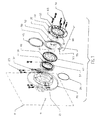
- Fig. 1 shows an exploded view of seal assembly 1 according to one preferred embodiment of this invention.
- seal assembly 1 is positioned around rotatable shaft 10 and adjacent vessel 8.
- Rotatable shaft 10 extends through wall 9 of vessel 8.
- Vessel 8 may be a mixer or other enclosure for holding and processing material that requires a rotatable shaft 10 extending through wall 9 thereof.
- the material within vessel 8 may gradually escape through a gap between rotatable shaft 10 and vessel 8. Such escaping material may contaminate material processing equipment or, in the case of hazardous material processing, result in a dangerous condition for workers exposed to such material processing equipment.
- sealing assembly provides a sealing engagement between vessel 8 and rotatable shaft 10 extending through wall 9 of vessel 8.
- seal apparatus 1 preferably includes insert retainer 20, shaft ring 30 and insert 40.
- Insert retainer 20 is mounted or connected with respect to vessel 8 and around rotatable shaft 10.
- Insert retainer 20 is preferably machined from stainless steel or similar material known to those having ordinary skill in the art. As shown in Figs. 1 and 3, insert retainer 20 is preferably separable into two insert retainer halves 20', 20". Such a configuration permits insert retainer 20 to be mounted with respect to vessel 8 without removal of rotatable shaft 10 from vessel 8. Further, seal assembly 1 according to a preferred embodiment of this invention is entirely separable to permit installation and maintenance with respect to vessel 8 without removal of rotatable shaft 10.
- Insert retainer 20 is positioned with respect to vessel 8 so that outer diameter 12 of rotatable shaft 10 is freely rotatable with respect to inner diameter 23 of insert retainer 20.
- insert retainer 20 is preferably assembled by joining two insert retainer halves 20', 20" with insert retainer screws 25 and aligning such insert retainer halves 20', 20" with alignment pins 22. Insert retainer 20 is then preferably connected with respect to vessel with fasteners and insert retainer mounting bores 21 to create a sealed engagement between insert retainer mounting bores 21 and vessel 8.
- end portions 29 of insert retainer halves 20', 20" may be removed to facilitate machining and assembly.
- Insert retainer 20 additionally comprises retainer plate mounting bores 28 positioned around an inner perimeter of insert retainer 20.
- Seal assembly further includes shaft ring 30 positioned on rotatable shaft 10.
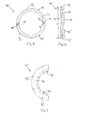
- Shaft ring 30, shown in Figs. 1 and 4 has inner diameter 32 approximately equal to or slightly greater than outer diameter 12 of rotatable shaft 10.
- shaft ring 30 is constructed from stainless steel or similar material and preferably comprises two shaft ring halves 30', 30' that are connected with respect to each other with shaft ring screws 34 through shaft ring bores 33, as shown in Fig. 4.
- Shaft ring 30 is connected to rotatable shaft 10 so that shaft ring 30 is rotatable with rotatable shaft 10.
- Shaft ring 30 is preferably connected to rotatable shaft 10 directly adjacent the wall of vessel 8.
- Shaft ring 30 is preferably rotatably positioned entirely within insert retainer 20. Shaft ring 30 does not directly contact insert retainer 20 within seal assembly 1.
- shaft ring 30 further comprises shaft ring groove 37 positioned circumferentially around inner diameter 32 of shaft ring 30.
- Shaft ring groove 37 is preferably a shallow channel positioned toward one end of shaft ring 30.
- Shaft ring groove 37 preferably accommodates shaft ring seal 35 positioned around inner diameter 32 of shaft ring 30.
- Shaft ring seal 35 may comprise an O-ring cord that is laid around shaft ring groove 37.
- O-ring cord is constructed from a fluorinated rubber such as Viton®, or other temperature and chemical resistant sealing material known to those having ordinary skill in the art.
- Shaft ring seal 35 preferably creates a sealing engagement between inner diameter 32 of shaft ring 30 and outer diameter of rotatable shaft 10.
- shaft ring 30 may not include shaft ring seal 35.
- seal assembly 1 further includes insert 40.
- Insert 40 is preferably constructed from Teflon® (polytetrafluoroethylene) or other similar material known to those having ordinary skill in the art. Like the other components discussed above, insert 40 preferably comprises two separable insert halves 40', 40". Insert 40 further includes inner face 42 that in an assembled seal assembly faces toward vessel 8 and outer face 43 that in an assembled seal assembly 1 faces away from vessel 8. Outer diameter 41 of insert 40 is approximately equal or slightly less than inner diameter 23 of insert retainer 20.
- insert 40 further includes insert groove 47 positioned circumferentially around insert 40.
- Insert groove 47 preferably accommodates sealing member 45.
- Sealing member 45 may comprise an O-ring cord, similar to shaft ring seal 35, laid around insert groove 47.
- insert 40 may not include insert groove 47 and/or sealing member 45.
- two separable insert halves 40', 40" are joined through axial notch 48 and axial groove 49 positioned at an interface between two separable insert halves 40', 40".
- Axial notch 48 and axial groove 49 maintain a fixed radial position of separable insert halves 40', 40" with respect to each other.
- the axial arrangement of axial notch 48 and axial groove 49 in combination with sealing member 45 around insert 40 help maintain an effective seal in seal assembly 1.
- Insert 40 and specifically inner face 42 is biased against shaft ring 30 and seated at least partially within insert retainer 20.
- insert 40 is positioned entirely within insert retainer 20. Sealing member 45 in insert 40 creates a sealed relationship between insert 40 and insert retainer 20.
- Retainer assembly 80 is preferably positioned adjacent insert 40 and maintains a fixed position of insert 40 with respect to shaft ring 30.
- retainer assembly 80 includes bias plate 50, retainer plate 60 and bias members 70.
- Retainer assembly 80 is preferably designed to maintain a fixed position of insert 40 with respect to shaft ring 30 and in addition minimize wear of insert 40 and other components within seal assembly 1.
- bias plate 50 has insert surface 53 and retainer surface 55 opposite insert surface 53.
- Bias plate 50 is divided into separable bias plate halves 50', 50" that are preferably connected with hinge 52.
- Bias plate 50 is preferably constructed from a thin piece of material having inner and outer diameters that approximately coincide with inner and outer diameters of insert 40.
- Insert surface 53 of bias plate 50 is preferably positioned against insert 40.
- bias plate 50 is biased against insert 40.
- Retainer assembly 80 further comprises retainer plate 60. As shown in Figs. 1 and 7, retainer plate 60 is separable into two separable retainer plate halves 60', 60".
- retainer plate 60 includes a plurality of bias member apertures 62 spaced around an inner perimeter of retainer plate 60.
- Retainer plate 60 preferably further includes a plurality of retainer apertures 63 spaced around an outer perimeter of retainer plate 60.
- Retainer plate 60 is preferably attached to insert retainer 20 with a plurality of retainer screws 65 positioned through retainer apertures 63 and threadedly mounted with respect to retainer plate mounting bores 28. Spacers 75 are preferably positioned around retainer screws 65 between retainer plate 60 and insert retainer 20.
- a plurality of bias members 70 are positioned through retainer plate 60 and biased against the bias plate 50.
- bias members 70 are preferably positioned through bias member apertures 62 in retainer plate 60 and biased against retainer surface 55 of bias plate 50.
- Bias members 70 may comprise spring loaded screws that exert a bias force against bias plate 50, which bias force is then translated from bias plate 50 to insert 40. Therefore, as a result of the bias force exerted on bias plate 50, insert 40 is biased against shaft ring 30.
- Vessels 8 such as mixers, specifically horizontal vacuum mixers, may generate internal vacuums of up to approximately 30". Additionally, rotatable shaft 10 may rotate in excess of 3600 revolutions per minute. Seal apparatus 1 according to this invention is effective for either of the above described conditions. As a result of the described rotation of rotatable shaft, shaft ring 30 rotates correspondingly in contact with insert 40. Therefore, inner face 42 of insert 40 may wear along contact surfaces with shaft ring 30. As such wear occurs, insert 40 remains in contact with shaft ring 30 because of the bias force exerted by bias members 70 indirectly upon insert 40. Bias plate 50 functions as a buffer between such bias force and insert 40.
Landscapes
- Engineering & Computer Science (AREA)
- General Engineering & Computer Science (AREA)
- Mechanical Engineering (AREA)
- Sealing Devices (AREA)
- Mechanical Sealing (AREA)
Applications Claiming Priority (2)
| Application Number | Priority Date | Filing Date | Title |
|---|---|---|---|
| US09/187,113 US6217028B1 (en) | 1998-11-05 | 1998-11-05 | Sealing apparatus for use with a rotatable shaft extending through a vessel |
| US187113 | 1998-11-05 |
Publications (2)
| Publication Number | Publication Date |
|---|---|
| EP1030085A2 true EP1030085A2 (de) | 2000-08-23 |
| EP1030085A3 EP1030085A3 (de) | 2001-12-12 |
Family
ID=22687652
Family Applications (1)
| Application Number | Title | Priority Date | Filing Date |
|---|---|---|---|
| EP99121855A Withdrawn EP1030085A3 (de) | 1998-11-05 | 1999-11-04 | Abdichtungsvorrichtung für eine sich durch einen Behälter erstreckende drehbare Welle |
Country Status (3)
| Country | Link |
|---|---|
| US (1) | US6217028B1 (de) |
| EP (1) | EP1030085A3 (de) |
| CA (1) | CA2288556A1 (de) |
Families Citing this family (5)
| Publication number | Priority date | Publication date | Assignee | Title |
|---|---|---|---|---|
| US6357756B1 (en) * | 1999-11-05 | 2002-03-19 | Chicago Seal Clamp | Balance shaft seal clamp |
| EP1323959B1 (de) * | 2001-12-27 | 2005-05-11 | Burgmann Dichtungswerke GmbH & Co. KG | Vorspanneinrichtung für eine Gleitringdichtungsanordnung |
| US7029393B2 (en) * | 2003-08-06 | 2006-04-18 | Carter Day International, Inc. | Split inlet seal for grain separators and method |
| US7121972B2 (en) * | 2003-10-30 | 2006-10-17 | Torque-Traction Technologies, Inc. | Adjustable flange device for cover member in drive axle assembly |
| US7862412B2 (en) * | 2008-06-20 | 2011-01-04 | Carter Day International, Inc. | Seal assemblies for grain separators |
Family Cites Families (14)
| Publication number | Priority date | Publication date | Assignee | Title |
|---|---|---|---|---|
| US3072414A (en) * | 1959-07-16 | 1963-01-08 | Flexibox Ltd | Mechanical seals for rotating parts |
| US4215870A (en) * | 1978-12-04 | 1980-08-05 | Escue Jesse W | Rotatable shaft seal |
| US4219202A (en) * | 1979-05-08 | 1980-08-26 | Tyton Seal, Inc. | Axial mechanical seal |
| US4423878A (en) * | 1982-03-29 | 1984-01-03 | Escue Jesse W | Sealing assembly, kit and method for rotatable shafts |
| DE3327131A1 (de) * | 1983-07-27 | 1985-02-07 | Erich 8151 Neukolbing Weichenrieder sen. | Wellendichtung fuer kunststoffverarbeitungsmaschinen |
| US4625977A (en) * | 1985-04-30 | 1986-12-02 | A. W. Chesterton Company | Convertible, stand-by rotary seal assembly |
| US4575098A (en) | 1985-08-19 | 1986-03-11 | Escue Jesse W | Rotatable shaft sealing assembly with flowable material spacer means |
| US4906008A (en) * | 1988-06-23 | 1990-03-06 | Gits Bros. Mfg. Co. | Mechanical seal |
| US5370401A (en) * | 1992-06-30 | 1994-12-06 | Eg&G Sealol, Inc. | Antirotational and axial force component in a pusher seal assembly and tool for wear installation |
| AU676466B2 (en) * | 1993-03-09 | 1997-03-13 | Robert Mconie | Flexible drive split mechanical seal |
| US5571268A (en) * | 1993-12-16 | 1996-11-05 | A.W. Chesterton Company | Universal split mechanical seal |
| US5538257A (en) * | 1994-12-30 | 1996-07-23 | Eg&G Sealol, Inc. | Spring device and method for holding a component on a shaft and pusher seal assembly using same |
| US5716054A (en) * | 1995-01-18 | 1998-02-10 | Bw/Ip International, Inc. | Diametric plane split mechanical face seal |
| US6120034A (en) * | 1997-12-17 | 2000-09-19 | A.W. Chesterston Company | Secondary sealing assembly for mechanical face seal |
-
1998
- 1998-11-05 US US09/187,113 patent/US6217028B1/en not_active Expired - Fee Related
-
1999
- 1999-11-04 EP EP99121855A patent/EP1030085A3/de not_active Withdrawn
- 1999-11-05 CA CA002288556A patent/CA2288556A1/en not_active Abandoned
Also Published As
| Publication number | Publication date |
|---|---|
| EP1030085A3 (de) | 2001-12-12 |
| US6217028B1 (en) | 2001-04-17 |
| CA2288556A1 (en) | 2000-05-05 |
Similar Documents
| Publication | Publication Date | Title |
|---|---|---|
| US5961122A (en) | Split mechanical face seal and method of assembly thereof | |
| EP0592113B1 (de) | Gleitringdichtung und Abdichtverfahren | |
| US4059205A (en) | Rotary valve | |
| US5114163A (en) | Split mechanical face seal | |
| US5199720A (en) | Split mechanical face seal | |
| US4572517A (en) | Labyrinth ring seals with housing mounting means | |
| AU712855B2 (en) | Triple cartridge seal having one inboard and two concentric seals for chemical processing pump | |
| JPH07198043A (ja) | 万能割りメカニカルシール | |
| US4294454A (en) | Rotary seal unit | |
| US5368311A (en) | Shaft seal assembly for a rotary valve | |
| JPH07198044A (ja) | 割りメカニカルシールのための固定及び心合装置 | |
| US9004491B2 (en) | Shaft seal assembly | |
| US5913521A (en) | Rotating seal ring component kit for a mechanical split seal | |
| US5409240A (en) | Seal with self-lubricating contact surface | |
| JPH06193742A (ja) | 強磁性流体シールセンタリングリング | |
| AU675153B2 (en) | Coupling rotor bodies to journals | |
| US6217028B1 (en) | Sealing apparatus for use with a rotatable shaft extending through a vessel | |
| EP0619448A1 (de) | Gleitringdichtung mit geteilten Ringen | |
| EP0958890A1 (de) | Drehverbindung für flüssigkeit | |
| JPH074529A (ja) | ラビリンスシール装置 | |
| US4215870A (en) | Rotatable shaft seal | |
| JP2003148629A (ja) | 流体漏れ防止用メカニカルシーリング装置 | |
| CA1302466C (en) | Positive bearing housing seal | |
| WO1997004256A1 (en) | Split mechanical face seal and method of assembly thereof | |
| FI67437B (fi) | Taetningsbox foer en pump ventil och liknande |
Legal Events
| Date | Code | Title | Description |
|---|---|---|---|
| PUAI | Public reference made under article 153(3) epc to a published international application that has entered the european phase |
Free format text: ORIGINAL CODE: 0009012 |
|
| AK | Designated contracting states |
Kind code of ref document: A2 Designated state(s): AT BE CH CY DE DK ES FI FR GB GR IE IT LI LU MC NL PT SE |
|
| AX | Request for extension of the european patent |
Free format text: AL;LT;LV;MK;RO;SI |
|
| PUAL | Search report despatched |
Free format text: ORIGINAL CODE: 0009013 |
|
| AK | Designated contracting states |
Kind code of ref document: A3 Designated state(s): AT BE CH CY DE DK ES FI FR GB GR IE IT LI LU MC NL PT SE |
|
| AX | Request for extension of the european patent |
Free format text: AL;LT;LV;MK;RO;SI |
|
| RIC1 | Information provided on ipc code assigned before grant |
Free format text: 7F 16J 15/34 A, 7F 16J 15/18 B |
|
| AKX | Designation fees paid | ||
| REG | Reference to a national code |
Ref country code: DE Ref legal event code: 8566 |
|
| STAA | Information on the status of an ep patent application or granted ep patent |
Free format text: STATUS: THE APPLICATION IS DEEMED TO BE WITHDRAWN |
|
| 18D | Application deemed to be withdrawn |
Effective date: 20020613 |