EP1030332A1 - Bedienungsschalter für elektrische Kochgeräte - Google Patents
Bedienungsschalter für elektrische Kochgeräte Download PDFInfo
- Publication number
- EP1030332A1 EP1030332A1 EP00420035A EP00420035A EP1030332A1 EP 1030332 A1 EP1030332 A1 EP 1030332A1 EP 00420035 A EP00420035 A EP 00420035A EP 00420035 A EP00420035 A EP 00420035A EP 1030332 A1 EP1030332 A1 EP 1030332A1
- Authority
- EP
- European Patent Office
- Prior art keywords
- button
- rotation
- control device
- crown
- series
- Prior art date
- Legal status (The legal status is an assumption and is not a legal conclusion. Google has not performed a legal analysis and makes no representation as to the accuracy of the status listed.)
- Withdrawn
Links
- 238000010411 cooking Methods 0.000 title claims description 4
- 238000010438 heat treatment Methods 0.000 claims abstract description 13
- 230000002093 peripheral effect Effects 0.000 claims description 4
- 230000000994 depressogenic effect Effects 0.000 claims description 3
- 240000000966 Allium tricoccum Species 0.000 description 4
- 241001080024 Telles Species 0.000 description 2
- 238000000465 moulding Methods 0.000 description 2
- 210000000056 organ Anatomy 0.000 description 2
- 239000012815 thermoplastic material Substances 0.000 description 2
- 240000007594 Oryza sativa Species 0.000 description 1
- 235000007164 Oryza sativa Nutrition 0.000 description 1
- 238000004140 cleaning Methods 0.000 description 1
- 230000000295 complement effect Effects 0.000 description 1
- 230000003670 easy-to-clean Effects 0.000 description 1
- 238000005485 electric heating Methods 0.000 description 1
- 238000007373 indentation Methods 0.000 description 1
- 230000003993 interaction Effects 0.000 description 1
- 230000014759 maintenance of location Effects 0.000 description 1
- 239000000463 material Substances 0.000 description 1
- 239000003607 modifier Substances 0.000 description 1
- 230000000717 retained effect Effects 0.000 description 1
- 235000009566 rice Nutrition 0.000 description 1
- 239000012780 transparent material Substances 0.000 description 1
Images


Classifications
-
- H—ELECTRICITY
- H01—ELECTRIC ELEMENTS
- H01H—ELECTRIC SWITCHES; RELAYS; SELECTORS; EMERGENCY PROTECTIVE DEVICES
- H01H13/00—Switches having rectilinearly-movable operating part or parts adapted for pushing or pulling in one direction only, e.g. push-button switch
- H01H13/50—Switches having rectilinearly-movable operating part or parts adapted for pushing or pulling in one direction only, e.g. push-button switch having a single operating member
- H01H13/56—Switches having rectilinearly-movable operating part or parts adapted for pushing or pulling in one direction only, e.g. push-button switch having a single operating member the contact returning to its original state upon the next application of operating force
- H01H13/58—Switches having rectilinearly-movable operating part or parts adapted for pushing or pulling in one direction only, e.g. push-button switch having a single operating member the contact returning to its original state upon the next application of operating force with contact-driving member rotated step-wise in one direction
-
- A—HUMAN NECESSITIES
- A47—FURNITURE; DOMESTIC ARTICLES OR APPLIANCES; COFFEE MILLS; SPICE MILLS; SUCTION CLEANERS IN GENERAL
- A47J—KITCHEN EQUIPMENT; COFFEE MILLS; SPICE MILLS; APPARATUS FOR MAKING BEVERAGES
- A47J37/00—Baking; Roasting; Grilling; Frying
- A47J37/12—Deep fat fryers, e.g. for frying fish or chips
- A47J37/1266—Control devices, e.g. to control temperature, level or quality of the frying liquid
Definitions
- the present invention relates to the general technical field of devices electric cooking including a housing and a tank associated with a heating element, and relates more particularly to a device for control accessible from outside the device so that the user can implement different functions.
- the fryer further comprises heating means disposed at the bottom of said housing and means for opening and closing the supply circuit electric heating means, such as a general on / off switch accessible from the outside, as well as temperature control means of the tank usually comprising a thermostat, a part of which comes thermal contact with the tank and including a control member accessible to the outside allows you to set the desired set temperature.
- heating means disposed at the bottom of said housing and means for opening and closing the supply circuit electric heating means, such as a general on / off switch accessible from the outside, as well as temperature control means of the tank usually comprising a thermostat, a part of which comes thermal contact with the tank and including a control member accessible to the outside allows you to set the desired set temperature.
- control devices appear generally prominently outside the outer face of the housing: either in the form of a large rotary button, whose first angles of rotation enable the main switch and the following angles of rotation are used to set the thermostat setpoint temperature.
- control means may consist of a strip moving at inside a groove.
- the object of the present invention is a control device for an apparatus electric cooking, in particular electric fryer, comprising a housing and a tank associated with heating means, capable of being produced so more discreet while remaining reliable in its operation and economical to achieve.
- the second rotation then makes it possible to shift the angular position of the pins or notches arranged on the button control with respect to the first series of ramps arranged opposite on the rotating part, so that a subsequent pressing of the button order again involves a rotation of the part.
- this device we transform a movement of a control button accessible from the outside, usually mobile in rotation or translation in the plane of the face of the housing, in a translational movement perpendicular to this plan of housing.
- the face of the housing is thus more waterproof. It’s also easier to clean, even when the device is in operation.
- the device according to the invention is of particular interest on a fryer, because this type of device gives off relatively oily vapors which may fall on the housing.
- the ease of cleaning provided by the control button flush with the facade is then appreciable.
- the rotary part is a crown arranged in a circular imprint of a support plate fixed between the external wall and a inner wall of the housing.
- one or more protruding hooks of the plate are engaged in a groove or behind a flange formed on the crown to proximity of its edge in contact with the plate, these hooks thus ensuring retention in translation of the crown.
- the first series of ramps is made on the face internal or external circular of the crown, and the organs capable of acting on the means for opening / closing the heating circuit, or capable of acting on the set point of the temperature control means, or able to act on the lid opening mechanism, are preferably arranged on the other circular side of the crown.
- the means for opening and closing the circuit electrical supply heating means comprise one or more switches whose housings are arranged near the crown, such so that their actuation button, kept at rest protruding out of their housing by internal elastic means, interacts with lugs of a series distributed regularly around the periphery of the external circular face of the crowned.
- This arrangement is characterized by its simplicity, therefore its reliability.
- the pins of the crown have a hollow in their vertex interacting with the buttons of the switches, so as to print, or help print the second rotation of the crown rotary when the device control button returns to its position rest.
- control button is in the form of a outwardly convex cap extended by a continuous portion, or several portions, cylindrical peripherals of corresponding height substantially to the thickness of the outer wall of the housing of the device, the edge internal of the cylindrical peripheral portion or portions being extended by a or portions of radial flanges coming into contact with the internal face of the outer wall of the device housing, when the control button is in the rest position.
- the cap of the control button is extended by one or several arms parallel to the axis of rotation of the part, these arms passing through corresponding openings in the support plate, the ends of these arms having hooks bearing against the face internal of the plate, one or more springs being arranged in support between the plate and the internal face of the cap, these springs being arranged either around of one of the arms, either contained in a tube protruding from the internal face of the cap and sliding in a protruding tube opposite the plate.
- control button is effectively held in translation against elastic means, which increases its operating reliability.
- the fryer includes a housing formed of an outer wall 2 and an inner wall 8, in which is placed a counter tank 7 delimiting an internal housing 4 in which is disposed a tank 6.
- At least one of the control buttons 20 of the fryer is flush with the surface outer wall 2 so as to avoid creating an asperity.
- the device first comprises a substantially flat support plate 30 attached by hooks 37 in the inner wall 8.
- This plate has a indentation 34 circular, substantially central, of depth included between 1 and 3 mm and with a diameter between 25 and 50 mm.
- three flexible hooks 36 protruding perpendicularly from the plate 30 are arranged regularly along the internal periphery of footprint, this number of hooks can vary from two to five, their height being between 2 and 5 mm.
- the center of the imprint 30 is further materialized by a protruding tube 51 with a height of 10 to 20 mm. Finally, fixing pins 33 are provided on the plate around the imprint 30.
- the openings in the plate around the hooks 32 and 36 show how this part can be produced simply by molding the thermoplastic material.
- a crown 10 free in rotation whose external diameter is slightly smaller than that of the cavity 34.
- the hooks 36 snap into a groove or behind a flange 18 formed near the circular edge of the crown in contact with plate 30. This hooking retains in translation the crown 10.
- a first series of ramps 14 is evenly distributed against the cylindrical internal face of the crown 10 and this slightly above the groove or flange 18.
- the active faces that is to say oriented along the axis of rotation of the crown, constitute small portions identical, adjacent spirals.
- the series may present between 30 and 40 ramps with a starting height of around 3 mm.
- a second regular series of ramps or hollow 16 interacting with the hooks 32, as will be better explained thereafter.
- the number of ramps or recesses 16 is identical to that of the first series.
- This external cylindrical face also has a series of pins identical actuators 12 regularly distributed over the periphery and protruding radially from the crown 10.
- the number of lugs is half the number of ramps in the first series.
- the height of these pins can be of the order of 3 to 6 mm.
- the summits of pins 10 each have a slight recess 13 at their top. If desired, a or several adjacent parallel series of lugs 12 may be provided on this external cylindrical face.
- switches 50 In the pads 33 of the plate 30 are engaged switches 50, their positioning being such that their engagement button 54 protruding out of each of the switch housings 52 interacts with the pins actuation 12.
- the button 54 of one of the switches 50 can be associated with a first series of lugs, the button on the other switch 50 'being associated with the adjacent series of lugs, which can then be angularly offset or have different lengths of vertices.
- the control device is completed by the button 20, appearing under the shape of a convex cap facing outwards, one of the diameters of which roughly corresponds to that of crown 10. As better visible on Figures 1a, 1b and 2, the periphery of this cap continues with cylindrical portions 26 extended by portions of radial flanges 27 outward facing.
- This button 20 also has a pair of arms 28 oriented parallel to the axis of rotation of the crown 10, and in the direction of the plate 30, such so pass through openings 38, made for this purpose in the plate.
- the end of these arms 28 includes in particular hooks 29, provided for come into engagement with the rear face of the plate 30. As illustrated, these arms 28 are preferably arranged at the end of portions of radial flanges 27.
- this button 20 further comprises one or more several series of notches 24 substantially identical to the ramps 14, with which they are facing.
- the control device described above operates in the manner next.
- Figure 1a is shown in section the assembled control device and the rest state, in which the spring 22 pushes the button 20 outwards which then is flush with the external face of the wall 2, its flange portions radials 27 bearing against the internal face of this wall 2.
- buttons 54 of the switches 50 are then located between two pins 12 of the crown 10, making these switches open and the means of heaters are not powered.
- the notches 24 of the button 20 come in contact with ramps 14 of the internal cylindrical face of the crown 10 and, by interaction of the ramps against each other, print on this crown 10, a rotational movement whose amplitude is defined by the width of these ramps and notches, in this case of the order of 10 degrees.
- the hooks 32 then being located just on the periphery of a recess 16, force a complementary rotation of the crown 10, so that these hooks 32 sink into the bottom of said recesses. This movement of additional rotation is also assisted by the buttons 54 switches 50 falling at the bottom of the hollows formed in the tops of the pins 12.
- buttons 54 of switches 50 to fall then between two pins, thus interrupting the connection made by these switches.
- the button 20 returns again to its rest position, flush with the outside of the camera body.
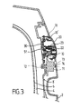
- Figure 3 shows a variant of the previous embodiment, in which another series of lugs 70 formed in the circular external face of the crown 10 'is meshed with a toothed wheel 71 having an axis 72 mounted on the inner wall 8 'of the housing.
- a window 73 formed in the wall outside 2 'of the box allows the user to see the indications on a front surface 74 of the wheel 71.
- the axis of the toothed wheel could cooperate by a gear mechanism with a rotary knob for adjusting the set temperature of a set temperature thermostat variable.
- said other series of pins provided in the circular external face of the crown could be meshed with cogwheels belonging to a mechanism for unlocking the cover.
- control according to the invention allows to implement a button control accessible from the outside, operating by translation perpendicular to the wall of the device, so that, in the rest position, it remains level with this wall.
- This device is therefore aesthetically pleasing particularly appreciated and easy to clean.
- it is practically impossible for dirt to get between the wall and the sliding control button.
- the crown 10 carries graduations and / or figures rotating behind an opening on the front of the button 20, this opening being able to be closed by a transparent material, the front face of the button 20 which can also be made of a material transparent.
- control device presented can be adapted for an apparatus comprising a tank in which a pressure prevails, such than a steamer or rice cooker, the control device being be arranged on the cover of the apparatus to actuate means of pressure control.
Landscapes
- Engineering & Computer Science (AREA)
- Food Science & Technology (AREA)
- Cookers (AREA)
Applications Claiming Priority (2)
| Application Number | Priority Date | Filing Date | Title |
|---|---|---|---|
| FR9902259A FR2790181B1 (fr) | 1999-02-19 | 1999-02-19 | Dispositif de commande pour un appareil electrique de cuisson |
| FR9902259 | 1999-02-19 |
Publications (1)
| Publication Number | Publication Date |
|---|---|
| EP1030332A1 true EP1030332A1 (de) | 2000-08-23 |
Family
ID=9542443
Family Applications (1)
| Application Number | Title | Priority Date | Filing Date |
|---|---|---|---|
| EP00420035A Withdrawn EP1030332A1 (de) | 1999-02-19 | 2000-02-17 | Bedienungsschalter für elektrische Kochgeräte |
Country Status (3)
| Country | Link |
|---|---|
| US (1) | US6218645B1 (de) |
| EP (1) | EP1030332A1 (de) |
| FR (1) | FR2790181B1 (de) |
Cited By (1)
| Publication number | Priority date | Publication date | Assignee | Title |
|---|---|---|---|---|
| BE1018115A3 (fr) * | 2008-05-06 | 2010-05-04 | Dalcq D M D Sociutu Anonyme | Friteuse amelioree. |
Families Citing this family (5)
| Publication number | Priority date | Publication date | Assignee | Title |
|---|---|---|---|---|
| US6825449B2 (en) | 2001-04-26 | 2004-11-30 | Tutco, Inc. | Cooling controller with push-to-turn rotary switch |
| US6794770B2 (en) | 2001-04-26 | 2004-09-21 | Tutco, Inc. | Interface control switch |
| US20180153348A1 (en) * | 2016-12-02 | 2018-06-07 | Ningbo Biyi Electric Appliance Co., Ltd | Oil filter of electric fryer |
| CN109491581B (zh) * | 2017-09-11 | 2022-02-18 | 佛山市顺德区美的电热电器制造有限公司 | 操作面板及其控制方法、烹饪厨具和机器可读存储介质 |
| FR3115668B1 (fr) * | 2020-10-29 | 2022-10-21 | Seb Sa | Couvercle chauffant amovible |
Citations (5)
| Publication number | Priority date | Publication date | Assignee | Title |
|---|---|---|---|---|
| FR2387625A1 (fr) * | 1977-04-19 | 1978-11-17 | Seb Sa | Friteuse, notamment a usage domestique |
| DE3022404A1 (de) * | 1980-06-14 | 1981-12-17 | Fa. Leopold Kostal, 5880 Lüdenscheid | Elektrischer druckschalter |
| US4506124A (en) * | 1983-10-19 | 1985-03-19 | Amp Incorporated | Push-push switch |
| EP0611542A1 (de) * | 1993-02-15 | 1994-08-24 | Seb S.A. | Heizvorrichtung zum Kochen oder Fritieren von Nahrungsmitteln, mit auf einer abnehmbaren Platte montierten Regelelementen |
| FR2738666A1 (fr) * | 1995-09-11 | 1997-03-14 | Robot Coupe Sa | Commutateur a trois positions |
Family Cites Families (11)
| Publication number | Priority date | Publication date | Assignee | Title |
|---|---|---|---|---|
| FR611542A (fr) | 1926-02-22 | 1926-09-30 | Contacteur pour l'utilisation rationnelle des bobinages dans un appareil de t. s. f. | |
| US3204067A (en) * | 1962-12-26 | 1965-08-31 | Boyne Products Inc | Push rotary switch construction with lost motion contact coupling |
| US3646297A (en) * | 1970-07-16 | 1972-02-29 | Circle F Ind Inc | Push switch, especially for ac use |
| US4771141A (en) * | 1987-07-31 | 1988-09-13 | Zanxx, Inc. | Push-push electrical switch |
| US4985605A (en) * | 1988-07-01 | 1991-01-15 | Judco Manufacturing, Incorporated | Compact switching apparatus and method of construction |
| US5145059A (en) * | 1989-06-29 | 1992-09-08 | Prince Corporation | Switch |
| US4996401A (en) * | 1989-06-29 | 1991-02-26 | Prince Corporation | Switch |
| US5043546A (en) * | 1990-07-16 | 1991-08-27 | Oslo Controls, Incorporated | Push-button switch |
| US5178265A (en) * | 1991-02-04 | 1993-01-12 | White Consolidated Industries, Inc. | Push-push snap switch |
| DE19517779C2 (de) * | 1995-05-15 | 2002-08-01 | Cherry Mikroschalter Gmbh | Tastschalter mit Raststellung |
| US5847345A (en) * | 1997-08-11 | 1998-12-08 | Harrison; Charles V. | Push button electrical switch |
-
1999
- 1999-02-19 FR FR9902259A patent/FR2790181B1/fr not_active Expired - Fee Related
-
2000
- 2000-02-17 EP EP00420035A patent/EP1030332A1/de not_active Withdrawn
- 2000-02-22 US US09/510,220 patent/US6218645B1/en not_active Expired - Fee Related
Patent Citations (5)
| Publication number | Priority date | Publication date | Assignee | Title |
|---|---|---|---|---|
| FR2387625A1 (fr) * | 1977-04-19 | 1978-11-17 | Seb Sa | Friteuse, notamment a usage domestique |
| DE3022404A1 (de) * | 1980-06-14 | 1981-12-17 | Fa. Leopold Kostal, 5880 Lüdenscheid | Elektrischer druckschalter |
| US4506124A (en) * | 1983-10-19 | 1985-03-19 | Amp Incorporated | Push-push switch |
| EP0611542A1 (de) * | 1993-02-15 | 1994-08-24 | Seb S.A. | Heizvorrichtung zum Kochen oder Fritieren von Nahrungsmitteln, mit auf einer abnehmbaren Platte montierten Regelelementen |
| FR2738666A1 (fr) * | 1995-09-11 | 1997-03-14 | Robot Coupe Sa | Commutateur a trois positions |
Cited By (1)
| Publication number | Priority date | Publication date | Assignee | Title |
|---|---|---|---|---|
| BE1018115A3 (fr) * | 2008-05-06 | 2010-05-04 | Dalcq D M D Sociutu Anonyme | Friteuse amelioree. |
Also Published As
| Publication number | Publication date |
|---|---|
| US6218645B1 (en) | 2001-04-17 |
| FR2790181B1 (fr) | 2001-05-18 |
| FR2790181A1 (fr) | 2000-08-25 |
Similar Documents
| Publication | Publication Date | Title |
|---|---|---|
| EP1317201B1 (de) | Kochgerät mit einer abnehmbaren heizplatte und einer verriegelungsvorrichtung für diese platte | |
| EP0942674B1 (de) | Haushaltsgerät mit rotierendem messer zur zubereitung von lebensmitteln versehen mit sicherheitsvorrichtung | |
| EP0805641B1 (de) | Küchengerät mit drehendem messer, wie ein häcksler | |
| EP1437260B1 (de) | Auf zwei Achsen rotierbarer Fahrzeugaussenrückspiegel | |
| EP3155940B1 (de) | Haushaltskochgerät | |
| FR2842088A1 (fr) | Bouilloire electrique | |
| EP0611542B1 (de) | Heizvorrichtung zum Kochen oder Fritieren von Nahrungsmitteln, mit auf einer abnehmbaren Platte montierten Regelelementen | |
| EP2923621A1 (de) | Elektrohaushaltsgerät zur essenszubereitung, das einen behälter umfasst, der mit einem abnehmbaren deckel verschlossen ist, der mit einer sicherheitsvorrichtung kombiniert ist | |
| EP3312862B1 (de) | Manuelle bedienungsvorrichtung für ein elektrohaushaltsgerät | |
| FR2939298A1 (fr) | Appareil electromenager de preparation culinaire comportant un boitier supportant un bras de transmission amovible au dessus d'un recipient de travail | |
| EP2433534B1 (de) | Haushaltsgerät mit einem Gefäß, das ein von einem Motor angetriebenes Schneidewerkzeug umfasst | |
| FR2790181A1 (fr) | Dispositif de commande pour un appareil electrique de cuisson | |
| FR2908620A1 (fr) | Appareil de preparation culinaire comportant des moyens particuliers d'immobilisation du recipient | |
| BE1018405A5 (fr) | Plaques de base pour dispositifs electriques encastrables. | |
| EP2433533A1 (de) | Haushaltsgerät mit einem Gefäss das ein von einem Motor angetriebenes Schneidewerkzeug umfasst | |
| EP2172142B1 (de) | Steuerverfahren zum Bewegen eines mobilen Organs einer Bedienblende eines Elektrohaushaltgeräts und entsprechendes Elektrohaushaltsgerät | |
| EP1566129B1 (de) | Elektrisches Haushaltsgerät zur Nahrungszubereitung | |
| FR2822364A1 (fr) | Appareil electromenager de preparation culinaire comportant un outil rotatif et un double dispositif de securite | |
| EP3312858B1 (de) | Manuelle bedienungsvorrichtung für ein elektrohaushaltsgerät | |
| FR2730796A1 (fr) | Appareil de cuisson muni d'un element chauffant mobile | |
| FR2623885A1 (fr) | Table de cuisson | |
| FR2789871A1 (fr) | Dispositif de securite et/ou de commande pour appareil electrique de cuisson | |
| EP1391172A1 (de) | Elektrisches Küchengerät mit rotierendem Werkzeug und verbesserter doppelter Sicherheitsvorrichtung | |
| FR2939297A1 (fr) | Appareil electromenager de preparation culinaire comportant un boitier supportant un bras de transmission amovible au dessus d'un recipient de travail | |
| FR2883407A1 (fr) | Variateur electromecanique et appareillage electrique comprenant un tel variateur |
Legal Events
| Date | Code | Title | Description |
|---|---|---|---|
| PUAI | Public reference made under article 153(3) epc to a published international application that has entered the european phase |
Free format text: ORIGINAL CODE: 0009012 |
|
| AK | Designated contracting states |
Kind code of ref document: A1 Designated state(s): AT BE CH CY DE DK ES FI FR GB GR IE IT LI LU MC NL PT SE |
|
| AX | Request for extension of the european patent |
Free format text: AL;LT;LV;MK;RO;SI |
|
| 17P | Request for examination filed |
Effective date: 20001222 |
|
| AKX | Designation fees paid |
Free format text: AT BE CH CY DE DK ES FI FR GB GR IE IT LI LU MC NL PT SE |
|
| GRAP | Despatch of communication of intention to grant a patent |
Free format text: ORIGINAL CODE: EPIDOSNIGR1 |
|
| STAA | Information on the status of an ep patent application or granted ep patent |
Free format text: STATUS: THE APPLICATION IS DEEMED TO BE WITHDRAWN |
|
| 18D | Application deemed to be withdrawn |
Effective date: 20060801 |