EP1030405A2 - Verbindungshülse oder Verbindermuffe oder Abzweigverbindungen für elektrische Kabel - Google Patents
Verbindungshülse oder Verbindermuffe oder Abzweigverbindungen für elektrische Kabel Download PDFInfo
- Publication number
- EP1030405A2 EP1030405A2 EP00660017A EP00660017A EP1030405A2 EP 1030405 A2 EP1030405 A2 EP 1030405A2 EP 00660017 A EP00660017 A EP 00660017A EP 00660017 A EP00660017 A EP 00660017A EP 1030405 A2 EP1030405 A2 EP 1030405A2
- Authority
- EP
- European Patent Office
- Prior art keywords
- quill
- loose
- connector
- set forth
- jointing sleeve
- Prior art date
- Legal status (The legal status is an assumption and is not a legal conclusion. Google has not performed a legal analysis and makes no representation as to the accuracy of the status listed.)
- Withdrawn
Links
Images

Classifications
-
- H—ELECTRICITY
- H01—ELECTRIC ELEMENTS
- H01R—ELECTRICALLY-CONDUCTIVE CONNECTIONS; STRUCTURAL ASSOCIATIONS OF A PLURALITY OF MUTUALLY-INSULATED ELECTRICAL CONNECTING ELEMENTS; COUPLING DEVICES; CURRENT COLLECTORS
- H01R4/00—Electrically-conductive connections between two or more conductive members in direct contact, i.e. touching one another; Means for effecting or maintaining such contact; Electrically-conductive connections having two or more spaced connecting locations for conductors and using contact members penetrating insulation
- H01R4/28—Clamped connections, spring connections
- H01R4/30—Clamped connections, spring connections utilising a screw or nut clamping member
- H01R4/36—Conductive members located under tip of screw
- H01R4/363—Conductive members located under tip of screw with intermediate part between tip and conductive member
Definitions
- the present invention relates to a jointing sleeve provided with moment screws for splice connections in electric cables, said jointing sleeve comprising a housing, both ends of which are provided with quill-shaped spaces for receiving the ends of cables to be connected.
- the invention relates also to a branch-wire connector, comprising a housing provided with reception slots for wires, one or more C-shaped clamping pieces, the ends of which are in line with the slots of the housing, and one or more clamping screws for tightening the clamping piece or pieces toward the housing, the wires thereby pressing against the walls of the slots.
- Such connectors for branch wires are known to have a problem in terms of corrosion, particularly when connecting branch wires of copper with main cables of aluminium.
- the connector which is typically made of aluminium, must be tin-plated. The same problem applies also to the above-mentioned jointing sleeve connections.
- the jointing sleeve shown in fig. 1 is manufactured from a streamline tubing, both ends of which are provided with quill-shaped spaces 5 for receiving the ends of electric cables to be connected as extensions of each other.
- a pressure-proof partition 2 which is made from a loose disc whose middle section is pressed (flattened by pressing) after the insertion, such that the disc rims have expanded tightly against the inner surface of the sleeve aperture.
- moment screws 4 On either side of the partition 2 there are two pieces of tapped holes 3 for moment screws 4. As the moment screw 4 is driven against the end of a wire or cable present within the sleeve, the head of the moment screw 4 breaks off upon reaching a sufficient tightness. If the metal of a wire to be connected is soft, the end of a moment screw deforms the wire and displaces some of the wire material, whereby the cross-section of the wire may become too small.
- loose quill 6 can be aluminium or soft annealed brass, which has a tin coating.
- the loose quill 6 has a bottom 6b which is preferably solid for further protection against corrosion.
- the quill 6 may have a conically flaring mouth 6a for facilitating the insertion of the end of a wire into the quill 6.
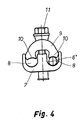
- the branch-wire connector shown in fig. 4 comprises a housing 7, which is provided with reception slots 8 for wires and to which is secured one or more C-shaped clamping pieces 9 by using one or more clamping screws 11.
- the clamping piece 9 has its ends 10 in line with the housing slots 8, the ends of wires to be connected or branched pressing against the walls of the slots 8 as the clamping piece 9 is tightened toward the housing 7 by means of the clamping screw 11.
- a loose quill 6' is fitted around the end of the copper wire, and the wire end, along with its loose quill 6', is placed in the slot 8.
- a proper material selection for the loose quill 6' can be used for eliminating corrosion without having to tin-plate the entire connector.
- the connector is made of aluminium and used as a connector between two copper wires, the loose quill 6' is placed in both slots 8 around the ends of wires to be connected.
- the loose quills 6 or 6' are manufactured in a plurality of diametral sizes to comply with the diameters of standard dimensioned wires, such that the wire can be readily inserted inside the quill 6 or 6'.
- the loose quill 6, 6' has a length which covers a necessary connection zone and, e.g. in the case of fig. 4, extends over the entire length of the slot 8, and preferably slightly beyond the end edges of the slot 8, in order to avoid a direct contact between the connector and the wire.
Landscapes
- Connections Effected By Soldering, Adhesion, Or Permanent Deformation (AREA)
Applications Claiming Priority (2)
| Application Number | Priority Date | Filing Date | Title |
|---|---|---|---|
| FI990311 | 1999-02-16 | ||
| FI990311A FI105296B (fi) | 1999-02-16 | 1999-02-16 | Jatkosholkki tai liitin sähkökaapeleiden jatkos- tai haaroitusliitoksia varten |
Publications (2)
| Publication Number | Publication Date |
|---|---|
| EP1030405A2 true EP1030405A2 (de) | 2000-08-23 |
| EP1030405A3 EP1030405A3 (de) | 2002-08-07 |
Family
ID=8553784
Family Applications (1)
| Application Number | Title | Priority Date | Filing Date |
|---|---|---|---|
| EP00660017A Withdrawn EP1030405A3 (de) | 1999-02-16 | 2000-02-02 | Verbindungshülse oder Verbindermuffe oder Abzweigverbindungen für elektrische Kabel |
Country Status (7)
| Country | Link |
|---|---|
| EP (1) | EP1030405A3 (de) |
| EE (1) | EE200000112A (de) |
| FI (1) | FI105296B (de) |
| HU (1) | HUP0000669A2 (de) |
| NO (1) | NO20000751L (de) |
| PL (1) | PL338161A1 (de) |
| RU (1) | RU2000104084A (de) |
Cited By (1)
| Publication number | Priority date | Publication date | Assignee | Title |
|---|---|---|---|---|
| EP2128932A3 (de) * | 2008-05-27 | 2011-04-20 | Ridelin, S.L. | Elektrischer Verbinder mit mechanischer Kompression für elektrische Leiter |
Families Citing this family (2)
| Publication number | Priority date | Publication date | Assignee | Title |
|---|---|---|---|---|
| AU2012200645A1 (en) * | 2011-02-08 | 2012-08-23 | Nexans | Arrangement with a Clamp of Metal Constructed as a Pipe Piece |
| CN115241685B (zh) * | 2022-08-17 | 2023-07-07 | 国网山东省电力公司临沭县供电公司 | 高空电缆连接端子 |
Family Cites Families (5)
| Publication number | Priority date | Publication date | Assignee | Title |
|---|---|---|---|---|
| FR885458A (fr) * | 1942-04-29 | 1943-09-16 | Perfectionnements aux raccords dits <aluminium-cuivre> pour lignes électriques | |
| US2806215A (en) * | 1953-11-04 | 1957-09-10 | Aircraft Marine Prod Inc | Aluminum ferrule-copper tongue terminal and method of making |
| FR1088501A (fr) * | 1953-11-30 | 1955-03-08 | Cosse pour la connection de câbles électriques | |
| FR2479577A1 (fr) * | 1980-03-28 | 1981-10-02 | Bonneau Albert | Connecteur electrique |
| FI216U1 (fi) * | 1992-04-16 | 1992-08-12 | Sekko Ab Oy | Foerlaengningsholk foersedd med momentskruvar |
-
1999
- 1999-02-16 FI FI990311A patent/FI105296B/fi active
-
2000
- 2000-01-31 PL PL00338161A patent/PL338161A1/xx not_active Application Discontinuation
- 2000-02-02 EP EP00660017A patent/EP1030405A3/de not_active Withdrawn
- 2000-02-14 EE EEP200000112A patent/EE200000112A/xx unknown
- 2000-02-15 NO NO20000751A patent/NO20000751L/no not_active Application Discontinuation
- 2000-02-15 RU RU2000104084/09A patent/RU2000104084A/ru not_active Application Discontinuation
- 2000-02-15 HU HU0000669A patent/HUP0000669A2/hu unknown
Cited By (1)
| Publication number | Priority date | Publication date | Assignee | Title |
|---|---|---|---|---|
| EP2128932A3 (de) * | 2008-05-27 | 2011-04-20 | Ridelin, S.L. | Elektrischer Verbinder mit mechanischer Kompression für elektrische Leiter |
Also Published As
| Publication number | Publication date |
|---|---|
| FI105296B (fi) | 2000-07-14 |
| FI990311A0 (fi) | 1999-02-16 |
| EP1030405A3 (de) | 2002-08-07 |
| EE200000112A (et) | 2000-10-16 |
| HUP0000669A2 (hu) | 2001-02-28 |
| PL338161A1 (en) | 2000-08-28 |
| NO20000751L (no) | 2000-08-17 |
| NO20000751D0 (no) | 2000-02-15 |
| HU0000669D0 (en) | 2000-04-28 |
| RU2000104084A (ru) | 2002-01-27 |
Similar Documents
| Publication | Publication Date | Title |
|---|---|---|
| US5683273A (en) | Mechanical splice connector for cable | |
| JP4165731B2 (ja) | 変形可能な本体及び圧縮リングを備えるfコネクタ | |
| AU641845B2 (en) | Connector twist tie | |
| US5423699A (en) | Electrical connector | |
| US20100227483A1 (en) | Midpoint cable electrical ground clamp | |
| US6004165A (en) | Multiple cable connector and method therefor | |
| JPH0434269B2 (de) | ||
| JP2007503683A (ja) | ケーブル接続システム | |
| US5055056A (en) | Ground wire connector | |
| US4610503A (en) | Protective device for overhead wires containing optical fiber units | |
| US6749179B2 (en) | Devices and methods for placing wiring into split loom tubing | |
| US5679032A (en) | Strain relief device for clamp assembly | |
| EP1078429B1 (de) | Zugentlastete eingeführte verbindung für signalkabel mit verdrillten drahtpaaren | |
| PL204196B1 (pl) | Kotew zaciskowa napowietrznego przewodu | |
| CA2266935A1 (en) | Armor stop for metal clad cable connector | |
| FI105296B (fi) | Jatkosholkki tai liitin sähkökaapeleiden jatkos- tai haaroitusliitoksia varten | |
| US7008244B2 (en) | Earthing pipes | |
| CZ187096A3 (en) | Rail coupling for attachment a ground cable to a safety band | |
| CA2461054C (en) | Electrical connector | |
| US5851124A (en) | Locking wire connector | |
| CZ2000472A3 (cs) | Spojovací objímka nebo konektor pro spojování elektrických kabelů nebo připojování odboček k elektrickým kabelům | |
| EP1349239A1 (de) | Erdungsklemme für Rohrleitung | |
| KR200276841Y1 (ko) | 발포동축케이블의 방수콘넥터 작업용 공구 | |
| JP2000056162A (ja) | 光ケーブル接続箱内クランプ | |
| EP0129353A2 (de) | Kabelverschraubung |
Legal Events
| Date | Code | Title | Description |
|---|---|---|---|
| PUAI | Public reference made under article 153(3) epc to a published international application that has entered the european phase |
Free format text: ORIGINAL CODE: 0009012 |
|
| AK | Designated contracting states |
Kind code of ref document: A2 Designated state(s): AT BE CH CY DE DK ES FI FR GB GR IE IT LI LU MC NL PT SE |
|
| AX | Request for extension of the european patent |
Free format text: AL;LT;LV;MK;RO;SI |
|
| PUAL | Search report despatched |
Free format text: ORIGINAL CODE: 0009013 |
|
| STAA | Information on the status of an ep patent application or granted ep patent |
Free format text: STATUS: THE APPLICATION HAS BEEN WITHDRAWN |
|
| AK | Designated contracting states |
Kind code of ref document: A3 Designated state(s): AT BE CH CY DE DK ES FI FR GB GR IE IT LI LU MC NL PT SE |
|
| AX | Request for extension of the european patent |
Free format text: AL;LT;LV;MK;RO;SI |
|
| 18W | Application withdrawn |
Withdrawal date: 20020531 |