EP1031027B1 - Verfahren und vorrichtung zum nachweis viskoser flüssigkeiten auf festem, insbesondere bewegtem untergrund - Google Patents
Verfahren und vorrichtung zum nachweis viskoser flüssigkeiten auf festem, insbesondere bewegtem untergrund Download PDFInfo
- Publication number
- EP1031027B1 EP1031027B1 EP98963354A EP98963354A EP1031027B1 EP 1031027 B1 EP1031027 B1 EP 1031027B1 EP 98963354 A EP98963354 A EP 98963354A EP 98963354 A EP98963354 A EP 98963354A EP 1031027 B1 EP1031027 B1 EP 1031027B1
- Authority
- EP
- European Patent Office
- Prior art keywords
- light
- detector
- viscous liquid
- liquid
- profile
- Prior art date
- Legal status (The legal status is an assumption and is not a legal conclusion. Google has not performed a legal analysis and makes no representation as to the accuracy of the status listed.)
- Expired - Lifetime
Links
Images


Classifications
-
- G—PHYSICS
- G01—MEASURING; TESTING
- G01N—INVESTIGATING OR ANALYSING MATERIALS BY DETERMINING THEIR CHEMICAL OR PHYSICAL PROPERTIES
- G01N21/00—Investigating or analysing materials by the use of optical means, i.e. using sub-millimetre waves, infrared, visible or ultraviolet light
- G01N21/84—Systems specially adapted for particular applications
- G01N21/86—Investigating moving sheets
-
- G—PHYSICS
- G01—MEASURING; TESTING
- G01B—MEASURING LENGTH, THICKNESS OR SIMILAR LINEAR DIMENSIONS; MEASURING ANGLES; MEASURING AREAS; MEASURING IRREGULARITIES OF SURFACES OR CONTOURS
- G01B11/00—Measuring arrangements characterised by the use of optical techniques
- G01B11/30—Measuring arrangements characterised by the use of optical techniques for measuring roughness or irregularity of surfaces
-
- G—PHYSICS
- G01—MEASURING; TESTING
- G01N—INVESTIGATING OR ANALYSING MATERIALS BY DETERMINING THEIR CHEMICAL OR PHYSICAL PROPERTIES
- G01N21/00—Investigating or analysing materials by the use of optical means, i.e. using sub-millimetre waves, infrared, visible or ultraviolet light
- G01N21/17—Systems in which incident light is modified in accordance with the properties of the material investigated
- G01N21/55—Specular reflectivity
-
- B—PERFORMING OPERATIONS; TRANSPORTING
- B31—MAKING ARTICLES OF PAPER, CARDBOARD OR MATERIAL WORKED IN A MANNER ANALOGOUS TO PAPER; WORKING PAPER, CARDBOARD OR MATERIAL WORKED IN A MANNER ANALOGOUS TO PAPER
- B31B—MAKING CONTAINERS OF PAPER, CARDBOARD OR MATERIAL WORKED IN A MANNER ANALOGOUS TO PAPER
- B31B50/00—Making rigid or semi-rigid containers, e.g. boxes or cartons
- B31B50/006—Controlling; Regulating; Measuring; Improving safety
-
- B—PERFORMING OPERATIONS; TRANSPORTING
- B31—MAKING ARTICLES OF PAPER, CARDBOARD OR MATERIAL WORKED IN A MANNER ANALOGOUS TO PAPER; WORKING PAPER, CARDBOARD OR MATERIAL WORKED IN A MANNER ANALOGOUS TO PAPER
- B31B—MAKING CONTAINERS OF PAPER, CARDBOARD OR MATERIAL WORKED IN A MANNER ANALOGOUS TO PAPER
- B31B50/00—Making rigid or semi-rigid containers, e.g. boxes or cartons
- B31B50/60—Uniting opposed surfaces or edges; Taping
- B31B50/62—Uniting opposed surfaces or edges; Taping by adhesives
- B31B50/622—Applying glue on already formed boxes
Definitions
- the invention relates to a method for detection viscous liquids on solid, especially agitated Substrate, for example flat packaging material such as cardboard, paper, cardboard, plastic or the like, in which the viscous liquid, especially glue, on one moving background in the form of a pattern is applied, then light from a Light source sent to and from the viscous liquid this is reflected, this reflected light periodic brightness profile obtained from a Detector received and then in a periodic electrical signal is converted with which the The presence of the viscous liquid is noted becomes.
- agitated Substrate for example flat packaging material such as cardboard, paper, cardboard, plastic or the like
- the invention also relates to a device for Carrying out the procedure with a storage container for the viscous liquid, especially glue, and one Application device for applying the viscous Liquid on the continuous path, one against the applied viscous liquid directed light source to illuminate the liquid and a detector to Detect the light reflected by the liquid.
- Devices which contain viscous liquids, especially glue, on a fast moving surface, For example, apply packaging material continuously.
- DE-C 195 20 190 discloses a device for monitoring the application of an adhesive to an object which is transported by a transport device and is provided with adhesive by means of an adhesive application device.
- a sensor determines the arrival of the object, the sensor being arranged at a predetermined location of the transport or conveying device.
- a distance measuring device measures the distance over which the conveying device conveys the object.
- image generation device which is arranged after the sensor, images of the glued object are produced.
- This known device further includes a time pulse generator for generating a time pulse, an adhesive pattern setting device for setting a pattern, and a comparison device for comparing a pattern defined by the adhesive pattern setting device with the images obtained from the image forming device.
- an illuminating device which illuminates the object at an angle to the axis to the illuminating device.
- the monitoring is carried out by means of at least one image of the reflected light, which is reflected by the object and the adhesive applied to the object. An alternation of light and shadow creates different gray levels on the image.
- DE-A 38 40 998 describes an operation for non-destructive detection of inhomogeneities in elastic materials with a load device for the deformation of the material and a Lighting device.
- the load device sends pulsed pressure waves on a by means of the Illumination device illuminated spot off and determined by means of an optical non-contact working distance measuring device the deformation of the Surface.
- the problem to be solved by this known State of the art is interference in elastic or viscoelastic materials with one Determine minimum effort.
- the known solution according to DE-C 195 20 190 is very complex in terms of apparatus due to the generation of comparative images, complicated in structure and nevertheless not reliable enough because it is difficult to distinguish between completely uniform substrates and adhesives.
- the other known solutions (DE-C 36 38 932, DE-A 38 40 998) have completely different objectives and tasks than the expert would have to consider.
- EP-A-0 300 734 Also known from EP-A-0 300 734 is a method and a device for determining the presence of a coating material on a moving web, for example adhesive strips on filter paper for cigarettes. Diffuse light from a fluorescent lamp is directed in a defined manner onto a very smooth or reflective coating. On the one hand, the reflections from the reflecting surface, and on the other hand the light diffusely scattered from the non-coated base are converted into an electrical signal and evaluated using a CCD scanner. The distinction between direct and diffuse light is made by the arrangement of detectors in a direction opposite the lamp, which corresponds to the normal reflection from a flat surface, and by the arrangement of reference detectors, in which only diffuse reflections are to be expected.
- the invention Task based on a method and an apparatus of improve the type mentioned in such a way that viscous Liquids on solid Underground continuously with the least effort are reliably detectable.
- the method according to the invention makes it possible to flat moving packaging webs made of paper, cardboard, Cardboard or plastic order the viscous Detect and close liquid continuously check. Because no special Properties of viscous liquids like physical ones and chemical parameters or sample images determined and need to be monitored is the inventive Process simple and uncomplicated with little effort perform.
- the device according to the invention can be easily in existing coating systems integrate. It is reliable, low maintenance, easy to use and requires no elaborate Modification of existing systems.
- a sheet 1 of cardboard with a glue 2 is to be wetted continuously in narrow strips.
- the glue 2 is located in the storage container 3 and is placed on a glue wheel 4 .
- the glue wheel 4 has according to the detail "A" (FIG. 2) a surface provided with notches 5 .
- a glue track is created with a periodically repeating profile which, conversely, is adequately designed for the surface profile of the glue wheel 4 (see detail "B" - FIG. 3).
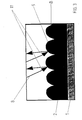
- a light source 6 and a photodetector 7 assigned to this light source are located close to the web 1 provided with the glue track. As shown in FIG. 4 , the light source 6 sends visible light 8 onto the profile 9 which is periodically deformed by the glue wheel 4 in the surface of the glue track , After a path W L has been covered , the light 8 falls on the wave-shaped profile 8, a part of the incident light 8 being reflected backwards.
- the light 8 is reflected at regular intervals in the direction of the photodetector 7 in accordance with the position and shape of the profile 9 and thus receives a fluctuating brightness profile.
- the photodetector 7 which has an inlet channel 10 , is positioned in the rear reflection region of this light. This inlet channel 10 is aligned so that it only allows the backward reflected light 11 into the detector 7 after covering a path W RL .
- the photodetector 7 is connected to an electronic circuit 12 , which is capable of continuously evaluating the determined brightness profile.
- the diameter D of the inlet channel 10 is so small compared to its length L that only the backward reflected light 11 can enter.
- FIG. 5 shows a variant of the device according to the invention, according to which, in addition to the glue wheel 4, a compressed air generation system 13 is used to deform the applied glue track.
- the glue wheel 4 is designed without notches.
- a feed pipe 14 with a nozzle 15 is brought up to close to the glue track.
- the feed pipe 14 opens at the other end into a compressed air container 16 , from which compressed air with periodically fluctuating pressure is pressed onto the glue track via the feed pipe 14 and the nozzle 15 .
- Fig. 7 shows the detailed structure of this compressed air generation system 13, which works on the air pump principle.
- a cylinder 17 in which a piston 18 is guided, opens into the supply pipe 14 and is sealed airtight to the outside.
- the piston 18 is connected by a connecting rod 19 to a drive wheel 21 driven by a motor 20 .
- the piston 18 sucks air out of the feed pipe 14 , as a result of which the excess pressure from the compressed air container 16 in the feed pipe 14 is compensated for and little air emerges from the nozzle 15 .
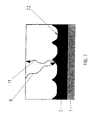
- the piston 18 moves in the direction of the feed tube 14 , it additionally presses air into the feed tube, as a result of which air emerges intermittently from the nozzle 15 and leaves depressions 22 in the glue track at regular intervals.
- the detail "C" in Fig. 6 shows the shape of such
- Indentation 22 and the light beam 8 emitted by the light source 6 which strikes the edge of the indentation 22 and is reflected there in the direction of the photodetector 7 .
- the electronic circuit 12 generates voltage pulses with the aid of a signal transmitter 23 , the time interval of which must correspond exactly to the time interval between two reflections at the edges of adjacent depressions 22 .
- the voltage pulses are obtained, for example, by a cam attached to the drive shaft. As long as there is a coincidence between the voltage pulses from the photodetector 7 and the voltage pulses from the signal generator 23 , the glue is present on the web 1 .
Landscapes
- General Physics & Mathematics (AREA)
- Physics & Mathematics (AREA)
- Immunology (AREA)
- Pathology (AREA)
- Analytical Chemistry (AREA)
- Biochemistry (AREA)
- General Health & Medical Sciences (AREA)
- Life Sciences & Earth Sciences (AREA)
- Health & Medical Sciences (AREA)
- Chemical & Material Sciences (AREA)
- Coating Apparatus (AREA)
- Package Closures (AREA)
- Investigating Or Analyzing Materials By The Use Of Magnetic Means (AREA)
- Application Of Or Painting With Fluid Materials (AREA)
- Making Paper Articles (AREA)
- Automatic Analysis And Handling Materials Therefor (AREA)
Description
In der Umgebung der Bilderzeugungseinrichtung befindet sich eine Beleuchtungseinrichtung, die den Gegenstand in einem Winkel zur Achse zur Beleuchtungseinrichtung beleuchtet. Die Überwachung wird mittels mindestens einem Bild des reflektierten Lichtes vorgenommen, das vom Gegenstand und dem auf den Gegenstand aufgebrachten Klebstoff reflektiert wird. Ein Wechsel von Licht und Schatten erzeugt unterschiedliche Graupegel auf dem Bild.
Die anderen bekannten Lösungen (DE-C 36 38 932, DE-A 38 40 998) haben gänzlich andere Zielstellungen und Aufgaben, als das sie der Fachmann in Betracht zu ziehen hätte.
Folglich arbeitet diese bekannte Lösung nur dann zufriedenstellend, wenn die beschichteten Flächen eindeutig hellere Reflexionen liefern als die nicht beschichteten Flächen. Daher ist dieses bekannte Verfahren nicht für gut reflektierende bzw. in weiten Grenzen nicht einheitlich reflektierende (unebene) Unterlagen geeignet wie sie beispielsweise in der Verpackungsindustrie anfallen.
Die gesamte Auswertung ist darüber hinaus aufwendig und kompliziert.
Diese Nachteile treffen auch für die aus dem Stand der Technik ferner bekannter Lösungen gemäß US-A-4704603 und US-A-4189335 zu.
- Fig. 1
- ein Funktionsschema des erfindungsgemäßen Verfahrens,
- Fig. 2
- eine Darstellung des Oberflächenprofils des Leimrades als Einzelheit A nach Fig. 1,
- Fig. 3
- eine Darstellung der Leimspur als Einzelheit B nach Fig. 1,
- Fig. 4
- eine vergroßerte Ansicht der profilierten Leimspur mit Darstellung der Reflexion des Lichtes einer Lichtquelle und Erfassung des Lichtes durch einen Photodetektor,
- Fig. 5
- ein Schema der erfindungsgemäßen Vorrichtung Mit Lichtquelle und Druckluftbeaufschlagung,
- Fig. 6
- den Aufbau der Drucklufterzeugung mit Einzelheit C gemäß Fig. 5.
- Fig. 7
- eine Darstellung der Leimspur als Einzelheit nach Fig. 5 und
- unter viskoser Flüssigkeit eine Substanz, die so verformbar ist, daß sie eine glatte, Licht reflektierende Oberfläche bildet, beispielsweise Leim zum Verkleben von Kartons, und die während des nachfolgend beschriebenen Verfahrens verformbar bleibt;
- unter festem Untergrund eine Verpackungsbahn, auf dem die viskose Flüssigkeit in fortlaufender Weise, beispielsweise in schmalen Streifen haftet.
Eine Lichtquelle 6 und ein dieser Lichtquelle zugeordneter Photodetektor 7 befinden sich nahe der mit der Leimspur versehenen Bahn 1. Die Lichtquelle 6 sendet, wie Fig. 4 zeigt, sichtbares Licht 8 auf das durch das Leimrad 4 periodisch verformte Profil 9 in der Oberfläche der Leimspur. Das Licht 8 fällt nach Zurücklegen eines Weges WL auf das wellenformige Profil 8, wobei ein Teil des einfallenden Lichts 8 rückwärts reflektiert wird. Durch die Fortbewegung der Bahn 1 wird das Licht 8 entsprechend der Lage und Form des Profils 9 in regelmäßigen Abständen in Richtung des Photodetektors 7 reflektiert und erhält somit ein schwankendes Helligkeitsprofil. Im rückwärtigen Reflexionsbereich dieses Lichtes ist der Photodetektor 7 positioniert, der einen Einlaßkanal 10 besitzt.
Dieser Einlaßkanal 10 ist so ausgerichtet, daß er nur das rückwärts reflektierte Licht 11 nach Zurücklegen eines Weges WRL in den Detektor 7 einläßt. Der Photodetektor 7 ist mit einer elektronischen Schaltung 12 verbunden, die fähig ist, das festgestellte Helligkeitsprofil kontinuierlich auszuwerten.
Der Durchmesser D des Einlaßkanals 10 ist gegenüber seiner Länge L so klein gewählt, daß nur das rückwärts reflektierte Licht 11 hineingelangen kann. Das ist immer dann der Fall, wenn das Verhältnis VD-L aus der Länge L zum Durchmesser D des Einlaßkanals 10 größer ist als das Verhältnis VA-PL aus dem Abstand A zwischen Einlaßkanal 10 und Profil 9 zur Länge PL des Profils 9, so daß vom vorhergehenden oder nachfolgenden Profil kein reflektiertes Licht in den Einlaßkanal 10 gelangen kann.
Die elektronische Schaltung 12 erzeugt in Abhängigkeit der Kreisfrequenz des Motors 20 mit Hilfe eines Signalgebers 23 Spannungsimpulse, deren zeitlicher Abstand genau dem zeitlichen Abstand zwischen zwei Reflexionen an den Rändern benachbarter Vertiefungen 22 entsprechen muß. Die Spannungsimpulse werden beispielsweise durch ein auf der Antriebswelle befestigten Nocken gewonnen. Solange Koinzidenz zwischen den Spannungsimpulsen aus dem Photodetektor 7 und den Spannungsimpulsen des Signalgebers 23 besteht, ist der Leim auf der Bahn 1 vorhanden.
Claims (14)
- Verfahren zum Nachweis viskoser Flüssigkeiten auf festem, insbesondere bewegtem Untergrund, beispielsweise flächigem Verpackungsmaterial wie Pappe, Papier, Karton, Kunststoff o. dgl., bei dem die viskose Flüssigkeit, insbesondere Leim, auf einen sich bewegenden Untergrund in Form eines Musters aufgetragen wird, anschließend Licht aus einer Lichtquelle auf die viskose Flüssigkeit gesendet und von dieser reflektiert wird, dieses reflektierte Licht ein periodisches Helligkeitsprofil erhält, das von einem Detektor empfangen und in ein periodisches elektrisches Signal umgewandelt wird, mit dem das Vorhandensein der Flüssigkeit festgestellt wird,
dadurch gekennzeichnet, daß der Oberfläche des auf den bewegten Untergrund aufgetragenen Musters aus viskoser Flüssigkeit ein definiertes und periodisch sich wiederholendes Profil aufgeprägt und von diesem Profil das Licht rückwärts in den Detektor reflektiert wird, wobei für die rückwärtige Reflexion des Lichtes ein Verhältnis (VD-L) aus der Länge (L) des Einlaßkanals des Detektors zum Durchmesser (D) des Einlaßkanals gilt, das größer ist, als das Verhältnis (VA-PL) aus dem Abstand (A) des Einlaßkanals vom Oberflächenprofil zur Länge (PL) des jeweiligen Oberflächenprofils. - Verfahren nach Anspruch 1, dadurch gekennzeichnet, daß dem Oberflächenprofil eine konkave oder konvexe Form aufgeprägt wird.
- Verfahren nach Anspruch 1 und 2, dadurch gekennzeichnet, daß zum Prägen des Oberflächenprofils der viskosen Flüssigkeit ein Leimrad oder ein periodisch sich verändernder Druck verwendet wird.
- Verfahren nach Anspruch 3, dadurch gekennzeichnet, daß der Druck mit Druckluft aufgebracht wird.
- Verfahren nach Anspruch 1, dadurch gekennzeichnet, daß Licht mit einer Wellenlänge von 300 nm bis 1200 nm, vorzugsweise sichtbares Licht oder Laserlicht, verwendet wird.
- Verfahren nach Anspruch 1, dadurch gekennzeichnet, daß das reflektierte Licht von einem Photodetektor erfaßt wird.
- Verfahren nach einem oder mehreren der vorherigen Ansprüche, dadurch gekennzeichnet, daß das Detektorsignal mit einem vom bewegten Untergrund gesteuerten Impulsgeber geregelt wird und/oder ausgewählte Detektoren gleichzeitig einen Lichtimpuls erhalten, um Schwankungen in der Bewegungsgeschwindigkeit des Untergrundes und Formschwankungen der Flüssigkeit zu kompensieren.
- Verfahren nach einem oder mehreren der vorherigen Ansprüche, dadurch gekennzeichnet, daß zur Umwandlung des Helligkeitsprofils in ein periodisches elektrisches Signal ein für das Licht empfindlicher Detektor verwendet wird, und daß mit den gewonnenen Signalen die Prozeßführung geregelt wird.
- Vorrichtung zur Durchführung des Verfahrens nach Anspruch 1, mit einem Vorratsbehälter für die viskose Flüssigkeit, insbesondere Leim, und einer Auftragseinrichtung zum Aufbringen der viskosen Flüssigkeit auf die fortlaufende Bahn, einer gegen die aufgetragene viskose Flüssigkeit gerichteten Lichtquelle zum Beleuchten der Flüssigkeit und einem Detektor zum Erfassen des von der Flüssigkeit reflektierten Lichtes, dadurch gekennzeichnet, daß ein profiliertes Leimrad (4) und/oder ein Drucklufterzeugungssystem zur Erzeugung eines periodischen Oberflächenprofils (9) mit definierten Reflexionsbereichen in der aufgetragenen viskosen Flüssigkeit vorgesehen ist, und daß der im Reflexionsbereich angeordnete Detektor (7) mit einem Einlaßkanal (10) versehen ist, dessen Verhältnis (VD-L) aus der Länge (L) des Einlaßkanals zum Durchmesser (D) des Einlaßkanals größer ist als das Verhältnis (VA-PL) aus dem Abstand (A) des Einlaßkanals (10) vom Oberflächenprofil (9) zur Länge (PL) des jeweiligen Oberflächenprofils, und daß der Detektor (7) mit einer elektronischen Schaltung (12) verbunden ist, die das Vorhandensein viskoser Flüssigkeit auf der Bahn anzeigt.
- Vorrichtung nach Anspruch 9, dadurch gekennzeichnet, daß die elektronische Schaltung (12) mit einem Signalgeber (23) verbunden ist.
- Vorrichtung nach Anspruch 9, dadurch gekennzeichnet, daß mehrere Detektoren (7) in Bewegungsrichtung des Untergrundes hintereinander angeordnet sind.
- Vorrichtung nach Anspruch 9, dadurch gekennzeichnet, daß in die Oberfläche des Leimrades (4) Kerben (5) eingeformt sind.
- Vorrichtung nach Anspruch 9, dadurch gekennnzeichnet, daß das Drucklufterzeugungssystem (13) aus einem Speicherbehälter (16) für Druckluft, einem an den Speicherbehälter angeschlossenen Zuführrohr (14) mit Düse (15), die unmittelbar über der Bahn (1) gegen die aufgetragene Flüssigkeit gerichtet angeordnet ist, einem an das Zuführrohr (14) angeschlossenen Zylinder (17) mit Kolben (18), der über eine Pleuelstange (19) mit einem Motor (20) verbunden ist, der mit einem Signalgeber (23) in Verbindung steht, welcher mittels der elektronischen Schaltung (12) in Abhängigkeit der Kreisfrequenz des Motors Spannungsimpulse liefert, deren zeitliche Abstände voneinander dem Abstand zweier Reflexionen entspricht.
- Vorrichtung nach Anspruch 9 bis 13, dadurch gekennzeichnet, daß der Detektor (7) ein Photodetektor ist.
Applications Claiming Priority (3)
| Application Number | Priority Date | Filing Date | Title |
|---|---|---|---|
| DE19750862A DE19750862C2 (de) | 1997-11-10 | 1997-11-10 | Vorrichtung zum Nachweis viskoser Flüssigkeiten auf festem, insbesondere bewegtem Untergrund |
| DE19750862 | 1997-11-10 | ||
| PCT/DE1998/003372 WO1999024819A1 (de) | 1997-11-10 | 1998-11-09 | Verfahren und vorrichtung zum nachweis viskoser flüssigkeiten auf festem, insbesondere bewegtem untergrund |
Publications (2)
| Publication Number | Publication Date |
|---|---|
| EP1031027A1 EP1031027A1 (de) | 2000-08-30 |
| EP1031027B1 true EP1031027B1 (de) | 2002-04-10 |
Family
ID=7848967
Family Applications (1)
| Application Number | Title | Priority Date | Filing Date |
|---|---|---|---|
| EP98963354A Expired - Lifetime EP1031027B1 (de) | 1997-11-10 | 1998-11-09 | Verfahren und vorrichtung zum nachweis viskoser flüssigkeiten auf festem, insbesondere bewegtem untergrund |
Country Status (5)
| Country | Link |
|---|---|
| EP (1) | EP1031027B1 (de) |
| AT (1) | ATE216077T1 (de) |
| AU (1) | AU1868599A (de) |
| DE (2) | DE19750862C2 (de) |
| WO (1) | WO1999024819A1 (de) |
Families Citing this family (6)
| Publication number | Priority date | Publication date | Assignee | Title |
|---|---|---|---|---|
| CA2342295C (en) * | 2000-04-04 | 2005-10-11 | Illinois Tool Works Inc. | Glue bead detection system |
| US7150559B1 (en) | 2002-09-25 | 2006-12-19 | Illinois Tool Works Inc. | Hot melt adhesive detection methods and systems |
| US7213968B2 (en) | 2002-09-25 | 2007-05-08 | Illinois Tool Works Inc. | Hot melt adhesive detection methods and systems |
| DE10252340B4 (de) * | 2002-11-05 | 2013-09-26 | Quiss Gmbh | Vorrichtung zum Erkennen einer auf einem Substrat aufzubringenden Struktur sowie geeignete Verfahren hierfür |
| US7208721B2 (en) | 2004-11-22 | 2007-04-24 | Illinois Tool Works Inc. | Controller for material dispensing nozzle control signal and methods |
| CN102519981A (zh) * | 2011-12-16 | 2012-06-27 | 湖南工业大学 | Pvc建材表面质量在线检测系统 |
Family Cites Families (8)
| Publication number | Priority date | Publication date | Assignee | Title |
|---|---|---|---|---|
| US3330961A (en) * | 1964-04-15 | 1967-07-11 | Eastman Kodak Co | Photoelectric skip detector for use with a viscous layer applicator |
| US4189335A (en) * | 1978-09-28 | 1980-02-19 | The Dow Chemical Company | Method for determining distribution of a coating composition on a carpet structure |
| US4704603A (en) * | 1986-04-24 | 1987-11-03 | Journey Electronics Corp. | Glue detection system |
| DE3638932A1 (de) * | 1986-11-14 | 1988-05-26 | Kaemmerer Gmbh | Verfahren zur messung von beschichtungsmengen, insbesondere von silikon-beschichtungen auf papier oder kunststoffolie |
| US4845374A (en) * | 1987-07-20 | 1989-07-04 | R. J. Reynolds Tobacco Company | Method and apparatus for detecting the deposition of an adhesive on a travelling web |
| DE3840998A1 (de) * | 1988-12-06 | 1990-06-07 | Battelle Institut E V | Vorrichtung zum zerstoerungsfreien aufspueren von inhomogenitaeten in elastischen werkstoffen |
| DE9305877U1 (de) * | 1993-04-20 | 1993-07-15 | hhs Leimauftrags-Systeme GmbH, 4030 Ratingen | Leimauftragsüberwachung |
| GB2289941B (en) * | 1994-06-03 | 1997-03-19 | Nireco Corp | Apparatus for monitoring glue application state |
-
1997
- 1997-11-10 DE DE19750862A patent/DE19750862C2/de not_active Expired - Fee Related
-
1998
- 1998-11-09 EP EP98963354A patent/EP1031027B1/de not_active Expired - Lifetime
- 1998-11-09 AU AU18685/99A patent/AU1868599A/en not_active Abandoned
- 1998-11-09 DE DE59803782T patent/DE59803782D1/de not_active Expired - Fee Related
- 1998-11-09 WO PCT/DE1998/003372 patent/WO1999024819A1/de not_active Ceased
- 1998-11-09 AT AT98963354T patent/ATE216077T1/de not_active IP Right Cessation
Also Published As
| Publication number | Publication date |
|---|---|
| DE19750862A1 (de) | 1999-06-02 |
| ATE216077T1 (de) | 2002-04-15 |
| EP1031027A1 (de) | 2000-08-30 |
| DE19750862C2 (de) | 2002-05-02 |
| DE59803782D1 (de) | 2002-05-16 |
| AU1868599A (en) | 1999-05-31 |
| WO1999024819A1 (de) | 1999-05-20 |
Similar Documents
| Publication | Publication Date | Title |
|---|---|---|
| DE19520190C2 (de) | Vorrichtung zur Überwachung eines Klebstoffauftrags | |
| DE10135010A1 (de) | Anordnung zum Steuern des Transportes von Druckprodukten durch eine drucktechnische Maschine | |
| EP1031027B1 (de) | Verfahren und vorrichtung zum nachweis viskoser flüssigkeiten auf festem, insbesondere bewegtem untergrund | |
| DE4304678C1 (de) | Verfahren zum kontinuierlichen Abtasten und Überprüfen von Spurauftragungen auf einer bewegten Unterlage und Vorrichtung zur Durchführung des Verfahrens | |
| DE19910699A1 (de) | Vorrichtung zum Messen der Breite eines Spalts | |
| EP1628241B1 (de) | Vorrichtung zur Erfassung von Strukturen, wie Profilierungen oder Prägungen, an Körpern von Flaschen oder dergl. Behälter | |
| WO1991010891A1 (de) | Verfahren und vorrichtung zur berührungslosen prüfung von flächigen und räumlichen prüfgütern | |
| DE10006663B4 (de) | Verfahren zur Vermessung von langwelligen Oberflächenstrukturen | |
| EP2270516A3 (de) | Analysesystem mit Mitteln zur Erkennung von Unterdosierungen | |
| DE4027709A1 (de) | Verfahren und vorrichtung zur ermittlung der dicke der von einer beschichtungsvorrichtung auf eine bahn aufgebrachten beschichtung | |
| DD219731A1 (de) | Einrichtung zur messung der farbdichte | |
| DE4318445A1 (de) | Verfahren zur Bestimmung der Beschichtungsdicke eines aufzutragenden Mediums | |
| EP1355148B1 (de) | Verfahren zum Erkennen der Anwesenheit von Fehlern, wie Rissen oder abgefasten Rändern, auf der Oberfläche von Holzbrettern | |
| DE4313889C2 (de) | Streicheinrichtung für laufende Bahnen aus Papier oder Karton | |
| DE10335685A1 (de) | Vorrichtung zum umseitigen Prüfen von Werkstücken | |
| WO2014082798A1 (de) | Verfahren und vorrichtung zum prüfen der vollständigkeit eines auftrags von einer transparenten schicht eines mediums auf einem trägermaterial | |
| DE102017122586A1 (de) | Handhabungsgerät | |
| DE10246449A1 (de) | Sensorsystem zum Erkennen der Lage von ringförmigen Einprägungen an Materialbahnen | |
| EP1728046B1 (de) | Vorrichtung und verfahren zum optischen detektieren eines materialauftrags | |
| CH677033A5 (de) | ||
| DE4315264A1 (de) | Verfahren und Vorrichtung zur berührungslosen Erkennung von Kanten an Gegenständen | |
| DE3218166A1 (de) | Einrichtung zur farbdichtemessung an bogen- oder bahnfoermigen, in bewegung befindlichen druckmaterialien | |
| DE2009001C3 (de) | Vorrichtung zur Abtastung von durchlaufendem Gut | |
| DE3927394A1 (de) | Vorrichtung zur dickenmessung | |
| DE102008001321A1 (de) | Verfahren und Vorrichtung zum Erkennen von transparenten Gegenständen |
Legal Events
| Date | Code | Title | Description |
|---|---|---|---|
| PUAI | Public reference made under article 153(3) epc to a published international application that has entered the european phase |
Free format text: ORIGINAL CODE: 0009012 |
|
| 17P | Request for examination filed |
Effective date: 20000509 |
|
| AK | Designated contracting states |
Kind code of ref document: A1 Designated state(s): AT BE CH CY DE DK ES FI FR GB GR IE IT LI LU MC NL PT SE |
|
| GRAG | Despatch of communication of intention to grant |
Free format text: ORIGINAL CODE: EPIDOS AGRA |
|
| GRAG | Despatch of communication of intention to grant |
Free format text: ORIGINAL CODE: EPIDOS AGRA |
|
| GRAH | Despatch of communication of intention to grant a patent |
Free format text: ORIGINAL CODE: EPIDOS IGRA |
|
| GRAH | Despatch of communication of intention to grant a patent |
Free format text: ORIGINAL CODE: EPIDOS IGRA |
|
| 17Q | First examination report despatched |
Effective date: 20010521 |
|
| REG | Reference to a national code |
Ref country code: GB Ref legal event code: IF02 |
|
| GRAA | (expected) grant |
Free format text: ORIGINAL CODE: 0009210 |
|
| AK | Designated contracting states |
Kind code of ref document: B1 Designated state(s): AT BE CH CY DE DK ES FI FR GB GR IE IT LI LU MC NL PT SE |
|
| PG25 | Lapsed in a contracting state [announced via postgrant information from national office to epo] |
Ref country code: NL Free format text: LAPSE BECAUSE OF FAILURE TO SUBMIT A TRANSLATION OF THE DESCRIPTION OR TO PAY THE FEE WITHIN THE PRESCRIBED TIME-LIMIT Effective date: 20020410 Ref country code: IT Free format text: LAPSE BECAUSE OF FAILURE TO SUBMIT A TRANSLATION OF THE DESCRIPTION OR TO PAY THE FEE WITHIN THE PRESCRIBED TIME-LIMIT;WARNING: LAPSES OF ITALIAN PATENTS WITH EFFECTIVE DATE BEFORE 2007 MAY HAVE OCCURRED AT ANY TIME BEFORE 2007. THE CORRECT EFFECTIVE DATE MAY BE DIFFERENT FROM THE ONE RECORDED. Effective date: 20020410 Ref country code: IE Free format text: LAPSE BECAUSE OF FAILURE TO SUBMIT A TRANSLATION OF THE DESCRIPTION OR TO PAY THE FEE WITHIN THE PRESCRIBED TIME-LIMIT Effective date: 20020410 Ref country code: GR Free format text: LAPSE BECAUSE OF FAILURE TO SUBMIT A TRANSLATION OF THE DESCRIPTION OR TO PAY THE FEE WITHIN THE PRESCRIBED TIME-LIMIT Effective date: 20020410 Ref country code: FR Free format text: LAPSE BECAUSE OF FAILURE TO SUBMIT A TRANSLATION OF THE DESCRIPTION OR TO PAY THE FEE WITHIN THE PRESCRIBED TIME-LIMIT Effective date: 20020410 Ref country code: FI Free format text: LAPSE BECAUSE OF FAILURE TO SUBMIT A TRANSLATION OF THE DESCRIPTION OR TO PAY THE FEE WITHIN THE PRESCRIBED TIME-LIMIT Effective date: 20020410 |
|
| REF | Corresponds to: |
Ref document number: 216077 Country of ref document: AT Date of ref document: 20020415 Kind code of ref document: T |
|
| REG | Reference to a national code |
Ref country code: CH Ref legal event code: EP |
|
| REG | Reference to a national code |
Ref country code: IE Ref legal event code: FG4D Free format text: GERMAN |
|
| REF | Corresponds to: |
Ref document number: 59803782 Country of ref document: DE Date of ref document: 20020516 |
|
| PG25 | Lapsed in a contracting state [announced via postgrant information from national office to epo] |
Ref country code: SE Free format text: LAPSE BECAUSE OF FAILURE TO SUBMIT A TRANSLATION OF THE DESCRIPTION OR TO PAY THE FEE WITHIN THE PRESCRIBED TIME-LIMIT Effective date: 20020710 Ref country code: PT Free format text: LAPSE BECAUSE OF FAILURE TO SUBMIT A TRANSLATION OF THE DESCRIPTION OR TO PAY THE FEE WITHIN THE PRESCRIBED TIME-LIMIT Effective date: 20020710 Ref country code: DK Free format text: LAPSE BECAUSE OF FAILURE TO SUBMIT A TRANSLATION OF THE DESCRIPTION OR TO PAY THE FEE WITHIN THE PRESCRIBED TIME-LIMIT Effective date: 20020710 |
|
| GBT | Gb: translation of ep patent filed (gb section 77(6)(a)/1977) |
Effective date: 20020712 |
|
| REG | Reference to a national code |
Ref country code: CH Ref legal event code: NV Representative=s name: BOVARD AG PATENTANWAELTE |
|
| NLV1 | Nl: lapsed or annulled due to failure to fulfill the requirements of art. 29p and 29m of the patents act | ||
| PG25 | Lapsed in a contracting state [announced via postgrant information from national office to epo] |
Ref country code: ES Free format text: LAPSE BECAUSE OF FAILURE TO SUBMIT A TRANSLATION OF THE DESCRIPTION OR TO PAY THE FEE WITHIN THE PRESCRIBED TIME-LIMIT Effective date: 20021030 |
|
| PGFP | Annual fee paid to national office [announced via postgrant information from national office to epo] |
Ref country code: GB Payment date: 20021107 Year of fee payment: 5 Ref country code: DE Payment date: 20021107 Year of fee payment: 5 |
|
| PG25 | Lapsed in a contracting state [announced via postgrant information from national office to epo] |
Ref country code: LU Free format text: LAPSE BECAUSE OF NON-PAYMENT OF DUE FEES Effective date: 20021109 |
|
| PGFP | Annual fee paid to national office [announced via postgrant information from national office to epo] |
Ref country code: CH Payment date: 20021112 Year of fee payment: 5 |
|
| PGFP | Annual fee paid to national office [announced via postgrant information from national office to epo] |
Ref country code: AT Payment date: 20021114 Year of fee payment: 5 |
|
| PG25 | Lapsed in a contracting state [announced via postgrant information from national office to epo] |
Ref country code: CY Free format text: LAPSE BECAUSE OF FAILURE TO SUBMIT A TRANSLATION OF THE DESCRIPTION OR TO PAY THE FEE WITHIN THE PRESCRIBED TIME-LIMIT Effective date: 20021130 Ref country code: BE Free format text: LAPSE BECAUSE OF NON-PAYMENT OF DUE FEES Effective date: 20021130 |
|
| REG | Reference to a national code |
Ref country code: IE Ref legal event code: FD4D Ref document number: 1031027E Country of ref document: IE |
|
| EN | Fr: translation not filed | ||
| PLBE | No opposition filed within time limit |
Free format text: ORIGINAL CODE: 0009261 |
|
| STAA | Information on the status of an ep patent application or granted ep patent |
Free format text: STATUS: NO OPPOSITION FILED WITHIN TIME LIMIT |
|
| 26N | No opposition filed |
Effective date: 20030113 |
|
| BERE | Be: lapsed |
Owner name: *LOERKE REINHARD Effective date: 20021130 |
|
| PG25 | Lapsed in a contracting state [announced via postgrant information from national office to epo] |
Ref country code: MC Free format text: LAPSE BECAUSE OF NON-PAYMENT OF DUE FEES Effective date: 20030601 |
|
| PG25 | Lapsed in a contracting state [announced via postgrant information from national office to epo] |
Ref country code: GB Free format text: LAPSE BECAUSE OF NON-PAYMENT OF DUE FEES Effective date: 20031109 Ref country code: AT Free format text: LAPSE BECAUSE OF NON-PAYMENT OF DUE FEES Effective date: 20031109 |
|
| PG25 | Lapsed in a contracting state [announced via postgrant information from national office to epo] |
Ref country code: LI Free format text: LAPSE BECAUSE OF NON-PAYMENT OF DUE FEES Effective date: 20031130 Ref country code: CH Free format text: LAPSE BECAUSE OF NON-PAYMENT OF DUE FEES Effective date: 20031130 |
|
| PG25 | Lapsed in a contracting state [announced via postgrant information from national office to epo] |
Ref country code: DE Free format text: LAPSE BECAUSE OF NON-PAYMENT OF DUE FEES Effective date: 20040602 |
|
| GBPC | Gb: european patent ceased through non-payment of renewal fee |
Effective date: 20031109 |
|
| REG | Reference to a national code |
Ref country code: CH Ref legal event code: PL |