EP1031189B1 - Empfänger mit aufwärtsumwandlung der aktiv gefilterten und begrenzten zwischenfrequenz - Google Patents
Empfänger mit aufwärtsumwandlung der aktiv gefilterten und begrenzten zwischenfrequenz Download PDFInfo
- Publication number
- EP1031189B1 EP1031189B1 EP98950918A EP98950918A EP1031189B1 EP 1031189 B1 EP1031189 B1 EP 1031189B1 EP 98950918 A EP98950918 A EP 98950918A EP 98950918 A EP98950918 A EP 98950918A EP 1031189 B1 EP1031189 B1 EP 1031189B1
- Authority
- EP
- European Patent Office
- Prior art keywords
- signal
- frequency
- limiter
- receiver
- filter
- Prior art date
- Legal status (The legal status is an assumption and is not a legal conclusion. Google has not performed a legal analysis and makes no representation as to the accuracy of the status listed.)
- Expired - Lifetime
Links
- 238000006243 chemical reaction Methods 0.000 title claims description 17
- 238000000034 method Methods 0.000 claims description 11
- 238000012545 processing Methods 0.000 claims description 11
- 238000001914 filtration Methods 0.000 claims description 10
- 238000013461 design Methods 0.000 description 5
- 230000001413 cellular effect Effects 0.000 description 3
- 230000009977 dual effect Effects 0.000 description 3
- 230000003071 parasitic effect Effects 0.000 description 3
- XUIMIQQOPSSXEZ-UHFFFAOYSA-N Silicon Chemical compound [Si] XUIMIQQOPSSXEZ-UHFFFAOYSA-N 0.000 description 2
- 239000000919 ceramic Substances 0.000 description 2
- 239000013078 crystal Substances 0.000 description 2
- 230000010354 integration Effects 0.000 description 2
- 229910052710 silicon Inorganic materials 0.000 description 2
- 239000010703 silicon Substances 0.000 description 2
- 238000004891 communication Methods 0.000 description 1
- 230000007812 deficiency Effects 0.000 description 1
- 238000011161 development Methods 0.000 description 1
- 230000018109 developmental process Effects 0.000 description 1
- 238000010586 diagram Methods 0.000 description 1
- 230000000694 effects Effects 0.000 description 1
- 238000004519 manufacturing process Methods 0.000 description 1
- 239000000463 material Substances 0.000 description 1
- 230000000630 rising effect Effects 0.000 description 1
- 230000003595 spectral effect Effects 0.000 description 1
- 230000001629 suppression Effects 0.000 description 1
Images

Classifications
-
- H—ELECTRICITY
- H04—ELECTRIC COMMUNICATION TECHNIQUE
- H04B—TRANSMISSION
- H04B1/00—Details of transmission systems, not covered by a single one of groups H04B3/00 - H04B13/00; Details of transmission systems not characterised by the medium used for transmission
- H04B1/06—Receivers
- H04B1/16—Circuits
- H04B1/26—Circuits for superheterodyne receivers
- H04B1/28—Circuits for superheterodyne receivers the receiver comprising at least one semiconductor device having three or more electrodes
Definitions
- the present invention relates generally to radio communication systems and, more specifically, to a multiple-conversion receiver where the final intermediate frequency (IF) stage operates at a higher frequency than the previous IF stage.
- IF intermediate frequency
- band pass filters are used to reduce noise and interference.
- additional filtering may be desired and a dual down conversion superheterodyne receiver may be used.
- the dual down conversion superheterodyne receiver 30 receives signals over an antenna 31.
- the received signal is then filtered in an RF filter 32 and amplified and mixed in a low noise amplifier/mixer 34 with a signal from the first local oscillator 36 to generate a first IF.
- the first IF signal is then filtered in the first IF filter 38.
- the first IF filter 38 is typically a passive crystal filter.
- a second IF stage 40 is provided for the second down conversion.
- the signal output by the first IF filter 38 is then amplified in an IF filter/mixer 42.
- the amplified signal is then mixed with a signal from a second local oscillator 44 to mix the signal down to a second IF.
- the second IF signal is then filtered in a second IF filter 46, typically a passive ceramic filter, and is output to an amplifier 48.
- This signal is then processed by detector 50 to detect the information symbols within the received signal using techniques that are well known to those skilled in the art.
- WO97/06604 discloses a universal receiver for processing RF signals modulated by various analogue and digital modulation techniques.
- the design of multiple-conversion superheterodyne receivers has traditionally followed two principles: (1) the conversion should result.in progressively lower intermediate frequencies - for example, a 100 MHZ signal might be converted to a first IF at 10.7 MHZ and then to a second IF at 455 KHz; and (2) the center frequency of the second IF should be as high as possible, commensurate with filter-performance limitations and adjacent-channel suppression requirements, in order to minimize the demand on the first IF filter to suppress mixing products that result from the second conversion and due to manufacturing constraints associated with the materials (e.g. crystal or ceramic) used to construct these filters.
- the materials e.g. crystal or ceramic
- the dynamic range of an active filter is related to the quality factor (Q). As Q increases, the dynamic range goes down (see Gert Groenewold, The Design of High Dynamic Range Continuous-Time Integratable Bandpass Filters , IEEE vol. 38, August 1991).
- Q quality factor
- the component spread in the filter structure also increases leading to a problem with parasitic capacitance. As the parasitic capacitance increases, the total capacitance used must increase to scale the impedance of the filter resulting in the requirement of more current. At high center frequencies, the parasitic capacitance changes the filter's pole positions and lowers the filter's tolerance to an impractical level. Therefore, the center frequency for the second IF should be low in order to produce a practical filter for integration in silicon.
- a higher second IF is needed for processing by baseband components such as detector 50.
- baseband components such as detector 50.
- One alternative is to redesign the baseband circuits so that they will function at lower IFs. However, redesigning the baseband circuits to operate at lower IFs would be time consuming and expensive.
- Another alternative is to design a higher IF active filter. However, designing an active filter for higher IF results in higher current and increased silicon area.
- this object is achieved by digitally mixing a low IF signal with a divided local oscillator signal to achieve a higher IF which is suited for processing by baseband components, such as a detector.
- the mixed signal is then filtered by a low dynamic range active filter.
- a filter's dynamic range is the range between the noise floor of the filter to the maximum input signal that the filter can handle without creating spurious frequency components.
- a low dynamic range active filter has a relatively small difference between these two values, such as 40 dB.
- a high dynamic range active filter on the other hand, has a greater difference, such as 70 to 80 dB.
- the low dynamic range active filter will be tuned based on characteristics of the main active filter which provides channel selectivity. After the signal is filtered by the low dynamic range filter, it is again limited to strip off unwanted components and to provide a clean signal.
- the oscillator signal operates at a reference frequency which can be adjusted according to the frequency requirement of the baseband component.
- a divider such as a programmable counter, can be employed for dividing the reference frequency to suit the baseband component.
- the digital mixing of the signal output from the high dynamic range filter and the reference signal can be performed using an exclusive-OR gate.
- the present invention provides a low IF backend receiver which is compatible with many different detectors.
- Exemplary implementations use low cost and low current elements to achieve the frequency conversion needed to adapt the signal for baseband processing.
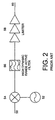
- FIG. 2 is a schematic block diagram of a conventional system for frequency mixing in the second IF stage of a superheterodyne receiver, e.g., stage 40 in Figure 1.
- An input frequency signal 50 is mixed with a local oscillator signal 52 at mixer 54.
- the input signal 50 is received from the output of a first IF filter of a double conversion receiver, e.g., filter 38 in Figure 1.
- the mixed signal is passed through a high dynamic range (e.g., greater than 70 dB) active filter 56 for channel selectivity.
- the high dynamic range active filter 56 also filters out interference and wideband noise.
- the signal is then limited by the limiter 58 to obtain the desired channel on signal line 60.
- This signal is then output to a post-IF processing device, e.g., a detector (not shown).
- the low IF signal is converted to the desired higher IF signal for facilitating processing by post-IF components.
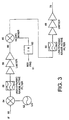
- Figure 3 illustrates a receiver branch according to an exemplary embodiment of the present invention wherein the same reference numerals from Figure 2 are used to identify similar elements in Figure 3. It will be appreciated that while one of the specific applications of the present invention is to cellular radio receivers, the present invention may be used in any signal receiving apparatus.
- the limited signal 60 at the second IF is digitally mixed, using a digital mixer 65, with a divided signal 64.
- the divided signal operates at a frequency that is the difference between the frequency of post-IF components and the frequency of the limited signal 60.
- the sum of frequency of the limited signal 60 and the frequency of the divided signal 64 is the desired frequency of the post-IF components.
- the dynamic range of the signal after the limiter is very low. Thus, all of the components after the first limiter have minimal dynamic range requirements.
- the reference frequency 61 can be adjusted to obtain the desired divided signal 64 in which case the value by which divider 62 adjusts the reference frequency is constant.
- the divider 62 can be programmable to allow adjustment of the value of the dividing circuit to obtain the desired frequency for divided signal 64. For the example given above where the second IF is 120 kHz and the desired, higher IF is 480 kHz, the divided signal operates at 360 kHz.
- the mixed signal is passed through a low dynamic range active filter 66 and a second limiter 68.
- This filter 66 rejects the unwanted mixing products which are produced by mixer 65. With adequate attenuation of the undesired signals, the desired signals are totally captured by the second limiter 68.
- the noise present in the low dynamic range filter is below the noise produced by the second limiter.
- the input to the low dynamic range filter 66 will be a constant amplitude square wave.
- the filter 66 can provide a linear filtering function of the input signal.
- the limiter 68 strips off the peak values of a sinusoidal input wave to produce a square wave.
- the limiter 68 further removes the amplitude noise from the signal and provides a clean signal 70 for output to the post-IF components that operate at higher IFs.
- a limiter is built-in; in this case, the second limiter 70 can be removed.
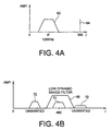
- Figure 4(a) illustrates an IF signal 60 being input to the digital mixer 65.
- the IF signal 60 has the illustrated spectral shape centered at 120 kHz.
- the divided frequency signal 64 operates at 360 kHz and is also input to mixer 65.
- Figure 4(b) illustrates the output of digital mixer 65.
- the output of mixer 65 includes the desired signal 70 as well as unwanted products 72 created by the multiplication of signals 60 and 64 in mixer 65.
- low dynamic range filter 66 has the filter characteristic illustrated in Figure 4(b) so as to pass component 70 and filter out unwanted components 72.
Landscapes
- Engineering & Computer Science (AREA)
- Computer Networks & Wireless Communication (AREA)
- Signal Processing (AREA)
- Superheterodyne Receivers (AREA)
Claims (19)
- Empfänger, enthaltend:einen Knoten zum Empfangen eines Hochfrequenz (HF) Signals;einen ersten Mischer (64) zum Abwärtsumsetzen des HF Signals zu einer Zwischenfrequenz (ZF);ein erstes Filter (38) zum Filtern des abwärts umgesetzten Signals zum Erzeugen eines Eingangs-ZF-Signals;einen zweiten Mischer (54) zum Mischen des Eingangs-ZF-Signals und eines Lokaloszillatorsignals (52) zum Erzeugen eines ersten Mischsignals;ein zweites Filter (56) zum Filtern des ersten Mischsignals, wobei das zweite Filter ein Aktivfilter ist;einen Begrenzer (58) zum Begrenzen des gefilterten Signals zum Ausgeben eines ersten Begrenzersignals (60); gekennzeichnet durcheine Frequenzumsetzvorrichtung (62, 65, 66, 68), angepasst zum Umsetzen des ersten Begrenzersignals zum Erzeugen eines Signals, das eine Frequenz aufweist, die höher ist als die Frequenz des ersten Begrenzersignals, für die Verarbeitung durch stromabwärtige Komponenten.
- Empfänger nach Anspruch 1, wobei das erste Mischsignal bei 120 KHz arbeitet.
- Empfänger nach Anspruch 1, wobei das umgesetzte Signal bei 480 KHz arbeitet.
- Empfänger nach Anspruch 1, wobei die stromabwärtigen Komponenten einen Demodulator enthalten.
- Empfänger nach Anspruch 1, wobei die Frequenzumsetzvorrichtung enthält:einen dritten Mischer (65) für das Aufwärtsumsetzen des ersten Begrenzersignals (60) zu dem umgesetzten Signal bei der Frequenz; undein drittes Filter (66) zum Filtern des umgesetzten Signals, wobei das dritte Filter ein aktives Filter ist.
- Empfänger, enthaltend:ein Zwischenfrequenz ZF Eingangssignal (50), das bei einer ersten Frequenz arbeitet;ein Lokaloszillatorsignal (52), abgeleitet von einem Synthesizer eines Empfängers und arbeitend bei einer zweiten Frequenz;einen Frequenzmischer (54) zum Mischen des Eingangssignals des Oszillatorsignals (54) zum Erzeugen eines ersten Mischsignals, das bei einer dritten Frequenz arbeitet;ein aktives Filter mit hohem Dynamikbereich (56) zum Ausfiltern der Interferenz und des Breitbandrauschens von dem ersten Mischsignal;einen Begrenzer (58) zum Begrenzen des Filtersignals von dem Filter und zum Ausgeben eines ersten Begrenzersignals (60); gekennzeichnet durcheinen digitalen Mischer (65) zum Mischen des ersten Begrenzersignals (60) mit einem geteilten Signalleitung (62), von einem Synthesizer eines Empfänders, arbeitend bei einer vierten Frequenz, zum Erzeugen eines zweiten Mischsignals, arbeitend bei einer fünften Frequenz;ein aktives Filter mit niedrigem Dynamikbereich (66) zum Ausfiltern ungewünschter Abschnitte des zweiten Mischsignals und zum Erzeugen eines zweiten gefilterten Signals; undeinen zweiten Begrenzer (58) zum Entfernen von Amplitudenrauschen von dem zweiten gefilterten Signal und zum Ausgeben eines zweiten Begrenzersignals, arbeitend bei einer Frequenz höher als die Frequenz des ersten Begrenzersignals, für die Verarbeitung durch eine Nach-ZF-Komponente.
- Empfänger nach Anspruch 6, wobei die dritte Frequenz die Summe der ersten Frequenz und der zweiten Frequenz ist.
- Empfänger nach Anspruch 6, wobei das Mischsignal bei 120 MHz arbeitet.
- Empfänger nach Anspruch 6, wobei die fünfte Frequenz die Summe der dritten Frequenz und der vierten Frequenz ist.
- Empfänger nach Anspruch 6, wobei der zweite Digitalmischer ein Exklusiv-ODER (XOR) Gatter ist.
- Empfänger nach Anspruch 6, wobei das geteilte Signal bei 360 KHz arbeitet.
- Empfänger nach Anspruch 6, wobei das zweite Mischsignal eine Rechteckwelle konstanter Amplitude ist.
- Verfahren zum Vorbereiten eines Empfangssignals für die Demodulation, wobei das Verfahren folgende Schritte enthält:Mischen eines Zwischenfrequenz (ZF) Eingangssignals und eines Lokaloszillatorsignals zum Erzeugen eines ersten gemischten ZF Signals;Führen des ersten gemischten ZF Signals über ein erstes aktives Filter (56) zum Ausfiltern einer Interferenz und eines Breitbandrauschens und zum Erzeugen eines ersten gefilterten ZF Signals;Begrenzen des gefilterten ersten ZF Signals durch einen ersten Begrenzer (58) und Ausgeben eines ersten Begrenzer Zf Signals (60); gekennzeichnet durch die SchritteUmsetzen des ersten Begrenzer ZF Signals (60) zu einer Frequenz, die höher als die Frequenz des ersten Begrenzer ZF Signals ist, wobei die Umsetzung umfasst:Mischen, über einen digitalen Mischer (65), des ersten Begrenzersignals (60) mit einem geteilten Signal (62) von dem Lokaloszillator zum Erzeugen eines zweiten gemischten Signals;Filtern nicht gewünschter Abschnitte des zweiten gemischten Signals unter Verwendung eines aktiven Filters mit geringem Dynamikbereich (66) zum Erzeugen eines zweiten gefilterten Signals; undEntfernen von Amplitudenrauschen von dem zweiten gefilterten Signal unter Verwendung eines zweiten Begrenzers (68) zum Erzeugen eines Ausgangssignals (70) für die Verarbeitung durch eine Nach-ZF-Komponente.
- Verfahren nach Anspruch 13, wobei das erste Mischsignal bei 120 KHz arbeitet.
- Verfahren nach Anspruch 13, wobei das umgesetzte Signal bei 480 KHz arbeitet.
- Verfahren nach Anspruch 13, wobei der zweite digitale Mischer ein Exklusiv-ODER (XOR) Gatter ist.
- Verfahren nach Anspruch 13, wobei das geteilte Signal bei 360 KHz arbeitet.
- Verfahren nach Anspruch 13, wobei das zweite gemischte Signal eine Rechteckwelle konstanter Amplitude ist.
- Verfahren für den Empfang nach Anspruch 13, wobei der niedrige Dynamikbereich 40 dB beträgt.
Applications Claiming Priority (3)
| Application Number | Priority Date | Filing Date | Title |
|---|---|---|---|
| US970422 | 1997-11-14 | ||
| US08/970,422 US6112065A (en) | 1997-11-14 | 1997-11-14 | Low to higher if conversion for active filtered limited IF systems |
| PCT/US1998/020935 WO1999026350A1 (en) | 1997-11-14 | 1998-10-13 | Low to higher if conversion for active filtered limited if systems |
Publications (2)
| Publication Number | Publication Date |
|---|---|
| EP1031189A1 EP1031189A1 (de) | 2000-08-30 |
| EP1031189B1 true EP1031189B1 (de) | 2002-06-26 |
Family
ID=25516931
Family Applications (1)
| Application Number | Title | Priority Date | Filing Date |
|---|---|---|---|
| EP98950918A Expired - Lifetime EP1031189B1 (de) | 1997-11-14 | 1998-10-13 | Empfänger mit aufwärtsumwandlung der aktiv gefilterten und begrenzten zwischenfrequenz |
Country Status (7)
| Country | Link |
|---|---|
| US (1) | US6112065A (de) |
| EP (1) | EP1031189B1 (de) |
| KR (1) | KR20010024633A (de) |
| CN (1) | CN1137545C (de) |
| AU (1) | AU9683898A (de) |
| DE (1) | DE69806266T2 (de) |
| WO (1) | WO1999026350A1 (de) |
Families Citing this family (7)
| Publication number | Priority date | Publication date | Assignee | Title |
|---|---|---|---|---|
| WO2001029978A1 (en) * | 1999-10-20 | 2001-04-26 | Maxim Integrated Products, Inc. | High linearity fm demod for a 4fsk wlan transceiver |
| US6741847B1 (en) * | 2000-06-28 | 2004-05-25 | Northrop Grumman Corporation | Multi-carrier receiver frequency conversion architecture |
| TWI280754B (en) * | 2004-08-26 | 2007-05-01 | Interdigital Tech Corp | Method and apparatus for processing multiple wireless communication services |
| US9602144B2 (en) * | 2004-08-26 | 2017-03-21 | Interdigital Technology Corporation | Method and apparatus for processing multiple wireless communication services |
| US20060045126A1 (en) * | 2004-08-30 | 2006-03-02 | Interdigital Technology Corporation | Method and apparatus for adaptively selecting sampling frequency for analog-to-digital conversion |
| CN111224622B (zh) * | 2019-11-21 | 2023-07-25 | 中电科思仪科技股份有限公司 | 一种中心频率与带宽可调的噪声信号发生装置及方法 |
| CN115276689B (zh) * | 2022-05-25 | 2023-09-26 | 中国船舶集团有限公司第七二三研究所 | 一种动态范围可重构的接收装置及方法 |
Family Cites Families (13)
| Publication number | Priority date | Publication date | Assignee | Title |
|---|---|---|---|---|
| US3544899A (en) * | 1966-02-17 | 1970-12-01 | Igor Alexandrovich Gusyatinsky | Frequency-modulated receiver with decreased threshold level |
| US4580289A (en) * | 1981-12-30 | 1986-04-01 | Motorola, Inc. | Fully integratable superheterodyne radio receiver utilizing tunable filters |
| US4476586A (en) * | 1982-02-05 | 1984-10-09 | Pioneer Electronic Corporation | IF Signal processing circuit in a receiver |
| US4852123A (en) * | 1988-02-05 | 1989-07-25 | Motorola, Inc. | Nearly DC IF phase locked transceiver |
| US5193210A (en) * | 1991-07-29 | 1993-03-09 | Abc Auto Alarms, Inc. | Low power RF receiver |
| TW263640B (de) * | 1992-06-26 | 1995-11-21 | Philips Electronics Nv | |
| TW274665B (de) * | 1992-06-26 | 1996-04-21 | Philips Electronics Nv | |
| JPH07177054A (ja) * | 1993-12-21 | 1995-07-14 | Hitachi Ltd | ディジタル無線通信端末 |
| FI100921B (fi) * | 1995-01-19 | 1998-03-13 | Nokia Telecommunications Oy | Spektrinmittausvastaanotin |
| EP0872021A1 (de) * | 1995-08-04 | 1998-10-21 | Numa Technologies, Inc. | Universeller hf-empfänger |
| GB9605719D0 (en) * | 1996-03-19 | 1996-05-22 | Philips Electronics Nv | Integrated receiver |
| US5875390A (en) * | 1996-12-06 | 1999-02-23 | Advanced Micro Devices, Inc. | Programmable intermediate frequency RSSI system including an adjustable rectifying stage |
| US5852772A (en) * | 1997-02-25 | 1998-12-22 | Ericsson Inc. | Receiver IF system with active filters |
-
1997
- 1997-11-14 US US08/970,422 patent/US6112065A/en not_active Expired - Lifetime
-
1998
- 1998-10-13 DE DE69806266T patent/DE69806266T2/de not_active Expired - Fee Related
- 1998-10-13 KR KR1020007005277A patent/KR20010024633A/ko not_active Withdrawn
- 1998-10-13 EP EP98950918A patent/EP1031189B1/de not_active Expired - Lifetime
- 1998-10-13 WO PCT/US1998/020935 patent/WO1999026350A1/en not_active Ceased
- 1998-10-13 AU AU96838/98A patent/AU9683898A/en not_active Abandoned
- 1998-10-13 CN CNB98813098XA patent/CN1137545C/zh not_active Expired - Fee Related
Also Published As
| Publication number | Publication date |
|---|---|
| DE69806266T2 (de) | 2002-11-28 |
| EP1031189A1 (de) | 2000-08-30 |
| US6112065A (en) | 2000-08-29 |
| KR20010024633A (ko) | 2001-03-26 |
| CN1137545C (zh) | 2004-02-04 |
| CN1285976A (zh) | 2001-02-28 |
| DE69806266D1 (de) | 2002-08-01 |
| AU9683898A (en) | 1999-06-07 |
| HK1035452A1 (en) | 2001-11-23 |
| WO1999026350A1 (en) | 1999-05-27 |
Similar Documents
| Publication | Publication Date | Title |
|---|---|---|
| US8145172B2 (en) | Low-cost receiver using tracking filter | |
| EP0965167B1 (de) | Zwischenfrequenzsystem mit aktiven filtern | |
| AU755670B2 (en) | Direct conversion receiver | |
| US8145170B2 (en) | Low-cost receiver using tracking bandpass filter and lowpass filter | |
| US8798570B2 (en) | Accurate radio frequency filtering using active intermediate frequency feedback | |
| KR100279031B1 (ko) | 주파수변조수신기 | |
| KR19980024842A (ko) | 집적 영상 제거 믹서 | |
| US20040116096A1 (en) | Radio frequency receiver architecture with tracking image-reject polyphase filtering | |
| US7477706B2 (en) | Switched capacitor network for tuning and downconversion | |
| KR20070069170A (ko) | 저역 중간 주파수 라디오 수신기 회로들 | |
| MXPA02004802A (es) | Un metodo y sistema para la digitalizacion de radiofrecuencia de multiples canales, con selectividad analogica. | |
| GB2321354A (en) | Suppressing attenuation of low frequency signals in a radio receiver | |
| US20030223017A1 (en) | Quadratic nyquist slope filter | |
| US6112065A (en) | Low to higher if conversion for active filtered limited IF systems | |
| CA2456658C (en) | A mixer circuit with image frequency rejection, in particular for an rf receiver with zero or low intermediate frequency | |
| JPH11112462A (ja) | デジタル放送の受信機 | |
| Ducourant et al. | A 3 chip GaAs double conversion TV tuner system with 70 dB image rejection | |
| EP0576078A1 (de) | FM-Empfänger | |
| US20040116087A1 (en) | Radio frequency receiver architecture with on-chip tracking intermediate frequency filtering | |
| GB2342238A (en) | Digital terrestrial TV tuner | |
| HK1035452B (en) | Low to higher if conversion for active filtered limited if systems | |
| WO2006137007A1 (en) | Transmitter in wireless communication system | |
| Yanqing et al. | A design of front-end compatible with PAL & DVB-C | |
| JP2001285379A (ja) | ダイレクトコンバージョン受信装置 |
Legal Events
| Date | Code | Title | Description |
|---|---|---|---|
| PUAI | Public reference made under article 153(3) epc to a published international application that has entered the european phase |
Free format text: ORIGINAL CODE: 0009012 |
|
| 17P | Request for examination filed |
Effective date: 20000530 |
|
| AK | Designated contracting states |
Kind code of ref document: A1 Designated state(s): BE DE FI GB SE |
|
| 17Q | First examination report despatched |
Effective date: 20000905 |
|
| GRAG | Despatch of communication of intention to grant |
Free format text: ORIGINAL CODE: EPIDOS AGRA |
|
| RTI1 | Title (correction) |
Free format text: RECEIVER WITH LOW TO HIGHER IF CONVERSION FOR ACTIVE FILTERED AND LIMITED IF |
|
| GRAG | Despatch of communication of intention to grant |
Free format text: ORIGINAL CODE: EPIDOS AGRA |
|
| GRAH | Despatch of communication of intention to grant a patent |
Free format text: ORIGINAL CODE: EPIDOS IGRA |
|
| GRAH | Despatch of communication of intention to grant a patent |
Free format text: ORIGINAL CODE: EPIDOS IGRA |
|
| GRAA | (expected) grant |
Free format text: ORIGINAL CODE: 0009210 |
|
| AK | Designated contracting states |
Kind code of ref document: B1 Designated state(s): BE DE FI GB SE |
|
| PG25 | Lapsed in a contracting state [announced via postgrant information from national office to epo] |
Ref country code: FI Free format text: LAPSE BECAUSE OF FAILURE TO SUBMIT A TRANSLATION OF THE DESCRIPTION OR TO PAY THE FEE WITHIN THE PRESCRIBED TIME-LIMIT Effective date: 20020626 Ref country code: BE Free format text: LAPSE BECAUSE OF FAILURE TO SUBMIT A TRANSLATION OF THE DESCRIPTION OR TO PAY THE FEE WITHIN THE PRESCRIBED TIME-LIMIT Effective date: 20020626 |
|
| REG | Reference to a national code |
Ref country code: GB Ref legal event code: FG4D |
|
| REF | Corresponds to: |
Ref document number: 69806266 Country of ref document: DE Date of ref document: 20020801 |
|
| PGFP | Annual fee paid to national office [announced via postgrant information from national office to epo] |
Ref country code: SE Payment date: 20020919 Year of fee payment: 5 |
|
| PG25 | Lapsed in a contracting state [announced via postgrant information from national office to epo] |
Ref country code: SE Free format text: LAPSE BECAUSE OF FAILURE TO SUBMIT A TRANSLATION OF THE DESCRIPTION OR TO PAY THE FEE WITHIN THE PRESCRIBED TIME-LIMIT Effective date: 20020926 |
|
| PLBE | No opposition filed within time limit |
Free format text: ORIGINAL CODE: 0009261 |
|
| STAA | Information on the status of an ep patent application or granted ep patent |
Free format text: STATUS: NO OPPOSITION FILED WITHIN TIME LIMIT |
|
| 26N | No opposition filed |
Effective date: 20030327 |
|
| PGFP | Annual fee paid to national office [announced via postgrant information from national office to epo] |
Ref country code: DE Payment date: 20081201 Year of fee payment: 11 |
|
| PGFP | Annual fee paid to national office [announced via postgrant information from national office to epo] |
Ref country code: GB Payment date: 20081029 Year of fee payment: 11 |
|
| PG25 | Lapsed in a contracting state [announced via postgrant information from national office to epo] |
Ref country code: DE Free format text: LAPSE BECAUSE OF NON-PAYMENT OF DUE FEES Effective date: 20100501 |
|
| PG25 | Lapsed in a contracting state [announced via postgrant information from national office to epo] |
Ref country code: GB Free format text: LAPSE BECAUSE OF NON-PAYMENT OF DUE FEES Effective date: 20091013 |