EP1031259B1 - Procede et dispositif pour neutraliser une surface chargee d'electricite statique - Google Patents
Procede et dispositif pour neutraliser une surface chargee d'electricite statique Download PDFInfo
- Publication number
- EP1031259B1 EP1031259B1 EP98957402A EP98957402A EP1031259B1 EP 1031259 B1 EP1031259 B1 EP 1031259B1 EP 98957402 A EP98957402 A EP 98957402A EP 98957402 A EP98957402 A EP 98957402A EP 1031259 B1 EP1031259 B1 EP 1031259B1
- Authority
- EP
- European Patent Office
- Prior art keywords
- electrodes
- high voltage
- generators
- ions
- polarity
- Prior art date
- Legal status (The legal status is an assumption and is not a legal conclusion. Google has not performed a legal analysis and makes no representation as to the accuracy of the status listed.)
- Expired - Lifetime
Links
- 238000000034 method Methods 0.000 title claims description 24
- 230000003472 neutralizing effect Effects 0.000 title claims description 4
- 150000002500 ions Chemical class 0.000 claims description 104
- 239000000463 material Substances 0.000 claims description 13
- 230000005686 electrostatic field Effects 0.000 claims description 11
- 230000005684 electric field Effects 0.000 claims description 10
- 239000003990 capacitor Substances 0.000 claims description 9
- 230000004044 response Effects 0.000 claims description 6
- 230000010355 oscillation Effects 0.000 claims description 5
- 239000003989 dielectric material Substances 0.000 claims description 2
- 238000012544 monitoring process Methods 0.000 claims description 2
- 239000012811 non-conductive material Substances 0.000 claims description 2
- 230000001747 exhibiting effect Effects 0.000 claims 3
- 230000003068 static effect Effects 0.000 description 13
- 238000010586 diagram Methods 0.000 description 8
- 239000002184 metal Substances 0.000 description 8
- 238000006386 neutralization reaction Methods 0.000 description 7
- 238000004804 winding Methods 0.000 description 5
- 230000005591 charge neutralization Effects 0.000 description 3
- 230000009977 dual effect Effects 0.000 description 2
- 238000009434 installation Methods 0.000 description 2
- 230000007935 neutral effect Effects 0.000 description 2
- 238000004806 packaging method and process Methods 0.000 description 2
- 238000012545 processing Methods 0.000 description 2
- 230000003213 activating effect Effects 0.000 description 1
- 230000008901 benefit Effects 0.000 description 1
- 230000008859 change Effects 0.000 description 1
- 238000006243 chemical reaction Methods 0.000 description 1
- 238000000576 coating method Methods 0.000 description 1
- 238000005056 compaction Methods 0.000 description 1
- 239000004020 conductor Substances 0.000 description 1
- 239000000356 contaminant Substances 0.000 description 1
- 238000011109 contamination Methods 0.000 description 1
- 238000013461 design Methods 0.000 description 1
- 230000000694 effects Effects 0.000 description 1
- 238000005516 engineering process Methods 0.000 description 1
- 230000005284 excitation Effects 0.000 description 1
- 230000001939 inductive effect Effects 0.000 description 1
- 230000005012 migration Effects 0.000 description 1
- 238000013508 migration Methods 0.000 description 1
- 239000004033 plastic Substances 0.000 description 1
- 239000002985 plastic film Substances 0.000 description 1
- 229920006255 plastic film Polymers 0.000 description 1
- 238000002360 preparation method Methods 0.000 description 1
- 230000008569 process Effects 0.000 description 1
- 230000006798 recombination Effects 0.000 description 1
- 238000005215 recombination Methods 0.000 description 1
- 230000009467 reduction Effects 0.000 description 1
- 230000001172 regenerating effect Effects 0.000 description 1
- 230000032258 transport Effects 0.000 description 1
Images


Classifications
-
- H—ELECTRICITY
- H01—ELECTRIC ELEMENTS
- H01T—SPARK GAPS; OVERVOLTAGE ARRESTERS USING SPARK GAPS; SPARKING PLUGS; CORONA DEVICES; GENERATING IONS TO BE INTRODUCED INTO NON-ENCLOSED GASES
- H01T23/00—Apparatus for generating ions to be introduced into non-enclosed gases, e.g. into the atmosphere
-
- H—ELECTRICITY
- H05—ELECTRIC TECHNIQUES NOT OTHERWISE PROVIDED FOR
- H05F—STATIC ELECTRICITY; NATURALLY-OCCURRING ELECTRICITY
- H05F3/00—Carrying-off electrostatic charges
- H05F3/04—Carrying-off electrostatic charges by means of spark gaps or other discharge devices
Definitions
- This invention relates to apparatus and methods of providing positive and negative ions for controlling surface charge, for example, on stationary objects and on continuous moving webs of non-conductive material.
- These air ionizers commonly contain pointed ionizing electrodes and operate at voltages of several kilovolts supplied to the ionizer via heavily-insulated cables from remote generators positioned away from the moving web.
- such webs may be several feet wide, operate at high linear speeds, and exhibit wide variations in the amount of static charge requiring neutralization at any given time or location along the moving web.
- ion currents of about 0,0039 to 3,9 ⁇ A per linear cm (0,1 to 10 ⁇ A per linear inch) of the moving web are required for neutralization.
- Ionizers that operate at alternating voltages at the power line frequencies of 50-60 Hz are especially capable of efficient neutralization at reasonable cost.
- Line AC voltage at power-line frequency is applied to a high voltage transformer, the secondary winding of which produces about 4 kV to 10kV AC voltage at the power-line frequency.
- This secondary voltage is applied to ionizing electrodes that are commonly positioned within a grounded metal enclosure, with openings through which the electrodes extend. This creates very strong electric field in the vicinity of the electrodes for generating corona discharge.
- the corona discharge is used to create positive and negative ions in the surrounding air.
- Certain known AC air ionizers use two diodes connected to the output of the high voltage transformer to conduct currents of opposite directions and thus serve as half-wave rectifiers for the high voltages supplied through such diodes to ionizing electrodes of opposite polarities.
- the electrodes are located close to each other to help generate the intense electric field necessary for ionization.
- ionizers of this type if a web does not carry static charge to attract ions, ions of one polarity generated around an electrode during one half cycle are attracted to and are neutralized at the other electrode of opposite polarity during the subsequent half cycle, thereby providing self-balancing operation. All such conventional ionizers require heavily-insulated cabling between ionizing electrodes and high-voltage transformers mounted remotely from the electrodes because of the large size and heavy weight of such transformers.
- Bipolar pulsed-DC ionizers are capable of detecting the ionization current without employing complex external sensors and accompanying circuitry. For example, the voltage drop across a ground return resistor through which a flow of electrical charges is conducted away from the ionizing electrode can be sensed to provide an indication corresponding to the ionization current.
- this apparatus only monitors its own internal parameters and generally does not respond to charge levels on a moving web or other workpiece.
- Such ionizers generally require relatively large spacings, e.g. 7,6-30,5 cm (3"-12"), between the electrodes of opposite polarities. Circuitry design limitations commonly limit the alternating switching rate of the positive and negative generators to about 5 alternations per second. This low frequency makes pulsed DC technology impractical for neutralization of surface charges on fast-moving webs. Another limitation of these pulsed DC ionizers is the low output power of high voltage generators which are suitable for area ionization purposes, but typically insufficient for neutralization of surface charges on fast-moving webs.
- Air ionizers that operate on dual steady-state DC high voltage supplies have found only a limited use for neutralization of surface charge on moving webs. This is due to the difficulty of controlling balanced positive and negative ion generation, and due to the propensity of such ionizers to charge the surface instead of neutralize surface charges. While it is possible to achieve balanced ionization with steady-state dual DC ionizers, considerably higher costs are involved relative to AC ionizers. Devices of the types described above are disclosed in the literature (See, for example, U.S. Patent No. 5,432,454).
- two high voltage generators are operated to produce positive or negative voltages of about 3-15 kilovolts.
- the positive high voltage and negative high voltage are supplied to separate respective electrodes that are positioned in close proximity to the work piece (e.g., a moving web) to be neutralized with air ions.
- the generators which apply high voltages of predetermined polarities to the respective electrodes include ground return electrical paths through which electrical charges of polarities opposite to those of the electrodes are conducted away from the generators at rates corresponding to the rates of air ion generation by the respective electrodes.
- the respective ground return paths of the two high voltage generators are connected to a summing junction and associated metering circuitry.
- the positive electrodes act as the electrical potential reference for the negative electrodes positioned in close proximity thereto, and the negative electrodes act as the electrical potential reference for the positive electrodes to produce the desirable intense electrical field required for air ionization.
- the ionizing electrode of one polarity positioned in close proximity to an electrode of the opposite polarity, and the sufficient potential difference between the electrodes, substantially all ion current from positive electrodes flows to the negative electrodes, and substantially all ion current from negative electrodes flows to the positive electrodes in the absence of an external electrostatic field from a charged surface (or when only a weak field is present) in the immediate vicinity of the ionizing electrodes.
- the moving web when the moving web carries a negative electrostatic charge, its electrostatic field attracts the ions from positive electrodes. As a result, some positive ion current flows to the moving web to neutralize its surface charge, while the ion current from the negative electrodes significantly flows to the positive electrodes or back to the negative electrode during the inactive half cycles thereof.
- the DC component of the current in the system ground return thus changes from zero to the value directly related to the ion current that flows to the surface of the charged web.
- the resultant current that leaves the ionizer can be measured or otherwise monitored in the common ground return path as an indication of the polarity and magnitude of the charge on the surface.
- the ionizer acts as a sensor for the charge on the work piece. A signal from the ionizer can then be used to control the outputs of the generators without the need for external sensors.
- the ion currents from the electrodes are balanced in a setting resembling actual industrial installations where such ionizers are located near electrically grounded metal machine frame components.
- a web of material carries negligible or small static charge
- some ions will still be flowing away from the ionizer toward the metal machine frame. That flow of ions, if it is not balanced, may cause unintended charging of the web.
- the DC component of the current in the common ground return path should be substantially zero when the surface, such as moving web, does not carry static charges. This is accomplished by placing the ionizing electrodes in proximity to the grounded metal member, such as a plate, and the voltages applied to the ionizing electrodes are adjusted until the DC component of the current in the common ground return equals substantially zero.
- the associated high voltage generators may be of many different types for producing positive and negative voltages of different wave shapes and amplitudes.
- the advantage of the present invention is significantly increased when the two high voltage generators are operated to produce positive or negative voltages of about 3-15 kilovolts during respective operational half-cycles at a selected switching or repetition rate.
- the first generator produces only positive half-cycles of high-voltage and the other generator is substantially inactive.
- such other generator produces only negative half-cycles of high-voltage and the first generator is substantially inactive.
- the potential of ionizing electrodes connected to the active high voltage generator is elevated to air ionization levels while the ionizing electrodes connected to the inactive generator serve as a ground (or zero potential) reference.
- Quantities of positive and negative air ions accumulate around the ionizing electrodes. Ions of opposite polarity to the charge on the web are attracted toward the web. Ions of the same polarity as the charge on the web, and excess air ions of the first polarity that were not attracted to the web due, for example, to low levels of static charge on the web, are more actively attracted back either to the electrode that generated them when its potential changes substantially to zero, or to the electrode of opposite polarity during the excitation thereof.
- the high voltage generators in one embodiment of the invention include multiple stages of power conversion in which the high voltage output is produced by a high frequency inverter (operating typically at a frequency greater that 20KHz). Therefore the high-voltage, step-up transformers can be reduced in size and weight for convenient packaging and mounting adjacent the ionizing electrodes near the work piece. This eliminates heavily-insulated, high-voltage cabling conventionally utilized in A.C. ionizers between the electrodes and remotely-located high voltage generators.
- the alternating rate at which the generators are activated and inactivated may be in the range preferably between 50 cycles per second and 400 cycles per second.
- the output of the high voltage generators during their respective inactive half cycles are caused to be at substantially lower electrical potentials so that the ionizing electrodes connected to the associated generator act as the electrical potential reference to the active ionizing electrodes to produce the desirable intense electrical field required for ionization.
- the outputs of one or both of separate high voltage generators are selectively and independently controlled to control the net ion output.
- This allows desired levels of positive and negative ion currents to be achieved by changing the high voltages applied to the respective ionizing electrodes.
- the ratio of ion currents can be changed over a wide range from only positive ions to only negative ions, and including generally equal positive and negative ion currents for balanced ionization in order to neutralize the surface charge of any polarity and magnitude on a fast-moving web.
- the ion current attributable to one polarity of high voltage may be maintained at maximum level by reducing the high voltage applied to the electrode of the other polarity in order to most effectively neutralize surface charge of a known polarity.
- the ionizer may also be used as a charging device where desirable, for example, by installing electrodes adjacent to a metal roller that carries the web, and adjusting the output of the high voltage generators to produce predominantly positive (or predominantly negative) ions.
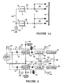
- two high-voltage generators 9, 11 are operated, as illustrated in Figure 1A, to produce only positive (or negative) high voltages 13, 15 on respective outputs 80, 82.
- the output voltages from each generator 9, 11 are supplied to respective sets of ion emitter electrodes 47, 49 that are conventionally formed as sharp tips or points oriented toward a workpiece that is to be neutralized by the supplied ions.
- Additional resistors 90, 92 of high resistance values may be connected between output terminals and ion emitter electrodes 47, 49 to limit maximum output current for safety purposes.
- the electrodes 47,49 are positioned in close proximity to the work piece 10 (e.g., a moving web) to be neutralized with air ions.
- the generators which apply high voltages of predetermined polarities to the respective electrodes include ground return electrical paths 109 and 111 through which electrical charges of polarities opposite to those of the electrodes are conducted away from the generators at rates corresponding to the rates of air ion generation by the respective electrodes 47 and 49.
- the respective ground return paths of the two high voltage generators are connected to a summing junction 113, similar to the circuitry described in U.S. Pat. No. 4,809,127 issued Feb. 28, 1989 to Arnold J.
- substantially all ion current from positive electrodes flows to the negative electrodes, and substantially all ion current from negative electrodes flows to the positive electrodes in the absence of an external electrostatic field from the surface 10 (or when only a weak field is present) in the immediate vicinity of the ionizing electrodes.
- the DC component of the current in the common ground return path 115 may be substantially zero when there are substantially no external electrostatic fields from a charged surface in the vicinity of the ionizing electrodes .
- the associated electrostatic field causes ions of the polarity opposite to the polarity of the surface charge on the web to leave the ionizing electrodes and flow to the charged surface.
- the resultant current that leaves the ionizer can be measured or otherwise monitored in the common ground return 115 as an indication of the polarity and magnitude of the charge on the surface.
- Figure 1B shows an embodiment of the present invention in which the ionizer is placed at a set distance from a electrically grounded metal plate 22 to simulate typical industrial installations.
- the current in the common ground return path 115 is measured with the metering circuit 107.
- the output of the high-voltage generator 9 (or of the high-voltage generator 11) is controlled to vary the effective ionizing potential supplied to the electrodes 47, while the ionizing potential on the electrode 49 is unchanged, until the ion currents from the electrodes are balanced and the DC component of the current in the common ground return is substantially zero.
- an imbalance in the quantities of positive and negative ions supplied to an initially neutral web 10 may produce residual charge on the web at locations downstream of the ionizer.
- the two high voltage generators 9, 11 are operated to produce positive or negative voltages of about 3-15 kilovolts during respective operational half-cycles at a selected switching or repetition rate.
- one generator produces only positive half-cycles of high-voltage and the other generator is substantially inactive.
- the alternate duty cycle such other generator produces only negative half-cycles of high-voltage and the one generator is substantially inactive.
- the operating duty cycles may be conveniently determined by power line frequency for alternately activating each of the separate high-voltage generators 9, 11 to produce half-cycles of high-voltage 13, 15 on the outputs 80, 82.
- each generator 9, 11 includes circuitry for operating at high frequency of about 20 kilohertz on applied electrical power, and such high frequency operation conveniently reduces the size and weight of voltage step-up transformers used to produce the high peak output voltages 13, 15 of one or other polarities.
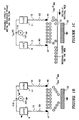
- FIG. 2 there is shown a block schematic diagram of the circuit stages including high-voltage generators 9, 11 whose ground return paths, in one embodiment, may be connected to one summing junction 113.
- the generators 9, 11 receive alternate half waves of applied power (e.g., conventional AC power-line supply) via respective half-wave rectifiers 19,21.
- the alternate half-cycles 23, 25 of the applied AC power 20 thus power the respective inverters 27, 29 to produce oscillations 31, 33 at high frequencies of about 20 kilohertz only during alternate half-cycles of the applied AC power 20.
- Such high-frequency oscillations at high-voltages of about 3-15 kilovolts are then half-wave rectified by respective diodes 35, 37 to supply the resultant half-wave rectified, high-frequency, high voltages to the respective filters 39, 41.
- These filters remove the high-frequency components of the half-wave rectified voltages to produce respective high-voltage outputs 43, 45 that vary over time substantially as the half-wave rectified, applied AC power 23, 25 varies with time.
- the filtered output voltages 43, 45 are supplied to separate respective sets of ion emitter electrodes 47, 49 of the type and orientation, as previously described.
- the inverters 27, 29 may be controlled in response to applied control signal to vary the effective ionizing potential supplied to respective electrodes 47, 49.
- a resistor 85 is connected between the outputs of the high voltage generators to provide substantially zero potential on the output and associated electrode 47, 49 that is inactive during an alternate half-duty cycle.
- the inverters 27, 29 may be directly controlled in conventional manner to alter the high voltage outputs supplied to the respective electrodes 47, 49 in response to applied control signal 101 derived, for example, as illustrated and described later herein with reference to Figure 3.
- an input filter network 50 including a varistor and inductive and capacitive elements for protecting against power-line voltage transients and electromagnetic interference.
- the applied AC power at line, or other, frequency and any convenient voltage level (e.g., 24 volts, 120 volts, 220 volts, etc.) is applied via diodes 19, 21 to respective high-frequency inverters 27, 29.
- the half-wave rectified applied AC voltage is filtered 52, 54 for application to the high-frequency oscillators 56, 58 that include voltage step-up transformers 60, 62.
- the step-up transformers 60, 62 each includes windings connected in respective drain or collector circuits of transistor pairs 68, 70.
- the step-up transformers include windings coupled to the base or gate circuits of the transistor pair to form regenerative feedback loops that sustain oscillating operation during conduction of power-line current through the associated diode 19, 21, substantially at a frequency determined by the tank circuit of capacitance 63, 65 and the primary inductance of winding 67, 69.
- the inductors 57, 59 smooth current flow to the parallel-resonant tank circuits of coils 67, 69 and capacitors 63, 65.
- Current transformers 64, 66 sample the collector or drain currents of transistor pair 68, 70 to provide a proportional current of reduced magnitude to drive the transistor pair 68, 70.
- the proportional drive current allows operation over a wide range of input voltages encountered during the half-sine wave variations in each alternate cycle.
- Each step-up transformer 60 and 62 includes output winding 72 or 74 connected to capacitive voltage doubler circuits 76, 78 that produce rectified high-voltages on output terminals 80, 82 of one or other polarity.
- the rectified output voltages filtered via capacitors 84, 86 to provide the output voltages 43, 45 that are applied to the respective ion emitter electrodes 47, 49.
- the output voltages 43, 45 should be adjusted to such levels relative to each other, or to the system ground, that the ionizing electrodes 47, 49 generate positive and negative ion currents of substantially equal magnitude to facilitate balanced ionization conditions.
- the resistor 85 of very high resistance (e.g., 50 megohms) is connected between output terminals to discharge the filter capacitors 84, 86, and additional resistors 90, 92 of high resistance values may be connected between output terminals and ion emitter electrodes 47, 49 to limit maximum output current supplied by the voltage doublers 76, 78.
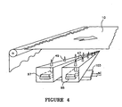
- the transformers 60, 62, 64, 66 and other components of small size for operation at high frequency promote convenient packaging in a common housing 103 for mounting with the ionizing electrodes 47, 49 near the moving web 10, as shown in Figure 4. Such mounting obviates exposed high-voltage cabling between the high voltage generator and ionizing electrodes and promotes safe, low-voltage connections from an AC power source to the housing 103.
- the metering circuit utilized to measure the DC component of the current in the common system ground return will be described in more detail. Electrical charges of polarities opposite to the charges on the ionizing electrodes are conducted away from the generators through the ground return electrical path 109 of the positive high-voltage generator 9 and ground return electrical path 111 of the negative high-voltage generator 11.
- the respective ground return paths 109 and 111 of the two high voltage generators are connected to a summing junction 113 and then to chassis ground through high resistance 105 which also functions as a return current sensing resistor.
- Further components of the metering circuit include a capacitor 106, connected in parallel with resistor 105 to serve as a filter.
- the voltage drop across resistance 105 is measured by DC voltmeter 107 or a similar instrument, as shown in Figure 3.
- This system ground return current thus indicates or monitors the polarity and magnitude of the net ion current that flows from the ionizer to the charged surface, and can be sensed to provide information about the charge levels on the moving web, or about the operation of the ionizer, or may be used to supply signal to inverters 27, 29 as illustrated in Figure 2 to control the levels of high voltages applied to the respective electrodes 47,49.
- FIG. 4 there is shown one embodiment of the electrodes 47, 49 connected to respective outputs 80, 82 and mounted in close proximity to a moving web 10.
- High voltage generators are packaged in a common housing 103 for mounting with the ionizing electrodes 47, 49 near the moving web 10. Such mounting obviates exposed high-voltage cabling between the high voltage generator and ionizing electrodes and promotes safe, low-voltage connections from an AC power source to the housing 103.
- rows of ionizing electrodes in the form of tapered pins 47, 49 are attached in common to high-voltage conductors 95, 97 of one or other polarity, and air ions of one polarity and then of opposite polarity are produced during alternate duty cycles in close proximity to the moving web 10 for controlling static charge on the web 10.
- the potential on one row of pins or electrodes 47, 49 is elevated to air ionization levels (e.g., 3-15 kilovolts) while the other row of pins or electrodes serves as a ground (or zero potential) reference for establishing high field gradients around the pins or electrodes 47, 49 to promote air ionization.
- the ionizing electrodes of both polarities may be aligned in a single row in alternating (-), (+), (-), (+) orientations, with spacing between adjacent electrodes in the range of about 6,35 to 50,8 mm (1/4 to 2 inches), and with preferred spacing of about 1/2 to 1 inch.
- the electrodes are positioned in pairs so that each electrode for positive voltage has an electrode for negative voltage as a neighbor, where the distance between the electrodes in the pairs is shorter than the distance between the pairs of the electrodes.
- conventional pulse-width modulators, or choppers 24, 26 are connected prior to the inverters 27, 29 to reduce the average (or integrated) input voltage 28, 30, but without substantially changing the envelope or waveshape of the voltage 28, 30 applied to the inverters 27, 29.
- the choppers 24, 26 as pulse-width modulators may include transistors, MOSFETs, or other similar switching devices which are turned off and on at frequencies comparable to the oscillation frequencies of the inverters with variable on-period controlled in response to applied control signal 101 derived from the output of an amplifier 117.
- the input of the amplifier 117 is connected to the metering circuit containing resistor 105 and capacitor 106.
- the ratio of the on-period to the total period (on and off) may remain constant over one complete half-cycle of the applied low frequency input 23, 25, with the result that the average output voltages of the choppers as applied to the inverters 27, 29 retain the half-sinusoidal waveshape at amplitudes that are reduced in relation to the reduction of the duty cycle.
- the DC component of the current in the ground return path indicates or monitors the polarity and magnitude of the net ion current, and can be used to supply signal to the choppers 24, 26 as illustrated in Figure 5, to control the levels of high voltages applied to the respective electrodes 47, 49.
- the self-balancing of charge neutralization on a moving web 10 may be enhanced by active control of one or other of the generators 9, 11 in response, for example, to the signal at the input 99 to the amplifier 117 that is representative of the net current in the system ground return.
- the circuit as illustrated in Figure 5 produces a control signal 99 for application to one or both of the generators 9, 11 in the manner as previously described to alter the ionizing potential of the output voltage produced thereby.
- a signal in the ground return indicating net positive ion current going to a charged web may be used to decrease the output of chopper 26 in the negative generator 11, and thus reduce the voltage on negative ionizing electrodes 49. Lowering the negative voltage effectively reduces the number of positive ions attracted and recombined with the negative electrode 49.
- the present invention may also be used to deposit charge on a surface by transferring the ions from the electrodes onto the surface for the purpose of, for example, so-called electrostatic 'pinning' of sheet and film material to other sheets or holding surfaces.
- ionizing electrodes are positioned adjacent a grounded surface such as a metal roller which transports the film material.
- the high voltage generators are adjusted to generate different ratios of positive and negative ionization currents for a bipolar charging of the surface, or a preponderance of ions of one polarity at the associated electrodes for a largely unipolar charging of the surface.
- the Coulomb forces established between the electrodes and the grounded metal roller move the ions toward the film material supported on the roller, thereby to charge the web of film material.
- the high voltage generators, ionizing electrodes, and control schemes according to the present invention provide supplies of positive and negative ions for control of static charge on a work piece such as a moving web of dielectric material.
- Self-balancing or signal control of electrostatic charge neutralization by generated air ions thus promote control of surface charge, for example, charge neutralization substantially to zero net charge for enhanced processing of the web material.
Landscapes
- Elimination Of Static Electricity (AREA)
Claims (40)
- Procédé pour neutraliser une surface chargée d'électricité statique à l'aide d'un système qui comprend une première et une deuxième électrode d'ionisation (47, 49) raccordées respectivement à un premier et à un deuxième générateur (9, 11) de haute tension qui délivrent séparément une haute tension positive et une haute tension négative à la première et à la deuxième électrode d'ionisation (47, 49) pour créer des ions positifs à partir de la première électrode (47) et des ions négatifs à partir de la deuxième électrode (49), le procédé comprenant les étapes qui consistent à :a) établir un retour à la masse commun (109, 111) pour ledit premier et ledit deuxième générateur (9, 11) de haute tension,b) évacuer l'écoulement de charges électriques de polarité opposée dudit premier générateur (9) de haute tension par le retour à la masse commun (109) à un taux qui correspond essentiellement au taux de production d'ions par la première électrode d'ionisation (47),c) évacuer l'écoulement de charges électriques de polarité opposée dudit deuxième générateur (11) de haute tension par le retour à la masse commun (111) à un taux qui correspond essentiellement au taux de production d'ions par la deuxième électrode d'ionisation (49),d) diriger essentiellement tous les ions de l'une et de l'autre polarité produits par la première et par la deuxième électrode (47, 49) pour qu'ils s'écoulent de ladite première et de ladite deuxième électrode (47, 49) à l'électrode (47, 49) de polarité opposée en l'absence d'un champ électrostatique extérieur au voisinage de ladite première et de ladite deuxième électrode (47, 49),e) disposer ladite première et ladite deuxième électrode (47, 49) à proximité d'une surface chargée d'électricité statique de niveau variable, notamment une charge essentiellement nulle, de l'une ou de l'autre polarité, ce qui permet d'établir un champ électrostatique entre la surface chargée, la première et la deuxième électrode (47, 49) pour amener une partie du courant ionique de l'électrode de polarité opposée à s'écouler dans la surface chargée,f) combiner les écoulements de charges électriques dudit premier et dudit deuxième générateur (9, 11) de haute tension par le retour à la masse commun (109, 111) à un taux qui correspond essentiellement au taux d'écoulement du courant ionique dans la surface chargée etg) détecter ledit écoulement combiné de charges électriques dudit premier et dudit deuxième générateur (9, 11) de haute tension.
- Procédé selon la revendication 1, dans lequel l'étape de détection de l'écoulement combiné de charges électriques dudit premier et dudit deuxième générateur (9, 11) de haute tension comprend les étapes qui consistent à mesurer et à surveiller la composante continue dudit écoulement combiné de charges électriques.
- Procédé selon les revendications 1 ou 2, dans lequel la composante continue dudit écoulement combiné de charges électriques dudit premier et dudit deuxième générateur (9, 11) de haute tension par leur retour à la masse commun (109, 111) est essentiellement nulle en l'absence d'un champ électrostatique extérieur au voisinage de la première et de la deuxième électrode.
- Procédé selon l'une des revendications précédentes, qui comprend l'étape qui consiste à :activer de manière intermittente et alternée ledit premier et ledit deuxième générateur (9, 11) de haute tension.
- Procédé selon la revendication 4, dans lequel, l'un parmi le premier et le deuxième générateur (9, 11) de haute tension est activé à l'étape d'activation pour produire une sortie à haute tension, tandis que la sortie de l'autre parmi le premier et le deuxième générateur (9, 11) de haute tension est essentiellement nulle.
- Procédé selon l'une quelconque des revendications précédentes, dans lequel les sorties à haute tension dudit premier et dudit deuxième générateur (9, 11) de haute tension peuvent être ajustées indépendamment.
- Procédé selon l'une quelconque des revendications précédentes, le procédé comprenant en outre les étapes qui consistent à :placer la première et la deuxième électrode (47, 49) à proximité de la surface et de la masse conductrice et, en l'absence de ladite surface, ajuster la composante continue de l'écoulement combiné de charges électriques dudit premier et dudit deuxième générateur de haute tension de telle sorte qu'elle soit essentiellement nulle.
- Procédé selon la revendication 7, dans lequel l'étape d'ajustement de la composante continue est effectuée en ajustant le niveau de la haute tension délivrée par au moins l'un parmi le premier et le deuxième générateur (9, 11) de haute tension.
- Procédé selon les revendications 7 ou 8, dans lequel ladite distance par rapport à la masse conductrice est comprise dans la plage d'environ 0,0254 m à 0,152 m (d'environ un pouce à environ six pouces).
- Procédé selon l'une des revendications 7 à 9, qui comprend en outre les étapes qui consistent à :g) positionner la première et la deuxième électrode (47, 49) à proximité de la surface chargée d'électricité pour établir un champ électrostatique externe au voisinage de ladite première et de ladite deuxième électrode (47, 49) de l'une et de l'autre polarité pour amener le courant ionique à s'écouler depuis l'une parmi la première et la deuxième électrode (47, 49) de polarité opposée jusque dans la surface chargée,h) établir l'écoulement combiné de charges électriques dudit premier et dudit deuxième générateur (9, 11) de haute tension par le retour à la masse commun (109, 111),i) établir en outre la composante continue dudit écoulement combiné de charges électriques pour qu'elle corresponde essentiellement au taux d'écoulement du courant ionique dirigé vers la surface chargée etk) détecter ladite composante continue de l'écoulement combiné de charges électriques dudit premier et dudit deuxième générateur (9, 11) de haute tension.
- Procédé selon l'une quelconque des revendications 7 à 10, qui comprend l'étape qui consiste à :activer ledit premier et ledit deuxième générateur (9, 11) de haute tension de manière intermittente et alternée.
- Procédé selon la revendication 11, dans lequel, l'un parmi le premier et le deuxième générateur (9, 11) de haute tension est activé à l'étape d'activation pour délivrer une sortie à haute tension, tandis que la sortie de l'autre parmi le premier et le deuxième générateur (9, 11) de haute tension est essentiellement plus basse.
- Procédé selon l'une quelconque des revendications précédentes, qui comprend un procédé pour délivrer, à partir de deux inverseurs qui peuvent tous deux être activés pour délivrer des oscillations à haute fréquence en réponse au signal électrique appliqué, des potentiels d'ionisation à des électrodes (47, 49) en vue d'ioniser l'air, le procédé comprenant les étapes qui consistent à :l) appliquer alternativement des signaux électriques sur les inverseurs pour alimenter en énergie chacun des inverseurs en opposition de phase en vue de les faire osciller à haute fréquence,m) former une sortie alternative à haute tension à partir des oscillations de chaque inverseur etn) redresser la sortie alternative à haute tension de chaque inverseur pour obtenir en fonctionnement la sortie à demi-alternance redressée de la sortie alternative à haute tension de l'inverseur associé dans un intervalle de temps pendant lequel il est alimenté en énergie par les signaux électriques appliqués pour délivrer un potentiel d'ionisation aux électrodes d'ionisation.
- Procédé selon la revendication 13, qui comprend les étapes qui consistent à :o) délivrer les ions produits par les électrodes d'ionisation (47, 49) dans une nappe mobile de matériau diélectrique en un emplacement sélectionné traversé par la nappe mobile, pour neutraliser la charge de la nappe etp) détecter la composante continue de l'écoulement combiné de charges électriques dudit premier et dudit deuxième générateur de haute tension dans un parcours commun de mise à la masse pour délivrer un signal de commande qui commande de manière sélective au moins les paramètres de quantité et de polarité des ions produits pour réduire la charge résiduelle qui reste dans la nappe après qu'elle s'est déplacée au-delà de l'emplacement où les ions sont délivrés dans la nappe.
- Procédé selon la revendication 14, dans lequel le signal de commande est délivré à au moins l'un des inverseurs pour modifier sélectivement leur sortie alternative à haute tension.
- Appareil pour neutraliser une surface chargée d'électricité statique, qui comprend :une première et une deuxième électrode (47, 49) qui peuvent être positionnées en position adjacente à une nappe de matériau éventuellement chargée d'électricité statique et qui sont disposées pour ioniser l'air en vue de délivrer des ions audit matériau,un premier générateur (9) de haute tension raccordé à la première électrode (47) pour lui appliquer une haute tension positive et un deuxième générateur (11) de haute tension raccordé à la deuxième électrode (49) pour lui appliquer une haute tension négative, le premier et le deuxième générateur (9, 11) de haute tension produisant chacun une sortie à haute tension qui peut être ajustée indépendamment,un parcours commun de mise à la masse (109, 111) par lequel les charges électriques de polarité opposée sont évacuées dudit premier et dudit deuxième générateur (9, 11) de haute tension,un circuit de commande qui active ledit premier et ledit deuxième générateur (9, 11) de haute tension pour qu'ils délivrent chacun de manière intermittente et alternée la haute tension positive et la haute tension négative essentiellement à la fréquence de l'alimentation en énergie,un circuit de détection raccordé audit parcours commun de mise à la masse (109, 111) qui détecte l'écoulement combiné de charges électriques dudit premier et dudit deuxième générateur (9, 11) de haute tension etun moyen d'accord qui maintient l'écoulement combiné de charges électriques dans le parcours commun de mise à la masse (109, 111) à un taux qui correspond essentiellement au taux d'écoulement des ions émis par la première et la deuxième électrode (47, 49) dans la surface chargée.
- Appareil selon la revendication 16, dans lequel ledit moyen d'accord comprend la première et la deuxième électrode (47, 49) distantes d'une distance à laquelle essentiellement tous les ions de l'air s'écoulent entre ladite première et ladite deuxième électrode (47, 49) en l'absence d'un champ électrique extérieur au voisinage de ladite première et de ladite deuxième électrode.
- Appareil selon la revendication 17, dans lequel ledit moyen d'accord comprend en outre un moyen qui crée une différence de potentiel entre la première et la deuxième électrode (47, 49), par laquelle essentiellement tous les ions de l'air s'écoulent entre ladite première et ladite deuxième électrode (47, 49) en l'absence d'un champ électrique extérieur au voisinage de ladite première et de ladite deuxième électrode.
- Appareil selon la revendication 16, dans lequel ledit moyen d'accord comprend la combinaison de la distance entre la première et la deuxième électrode (47, 49) et de la différence de potentiel entre la première et la deuxième électrode (47, 49), par laquelle essentiellement tous les ions de l'air s'écoulent entre ladite première et ladite deuxième électrode (47, 49) en l'absence d'un champ électrique extérieur au voisinage de ladite première et de ladite deuxième électrode.
- Appareil selon l'une des revendications 16 à 19, dans lequel la sortie dudit premier générateur (9) et celle dudit deuxième générateur (11) sont raccordées par une résistance (85).
- Appareil selon la revendication 20, dans lequel ladite résistance (85) présente une valeur de résistance sélectionnée pour rendre la sortie de l'un des générateurs (9, 11) de haute tension essentiellement nulle lorsque la sortie de l'autre générateur (11,9) de haute tension est élevée.
- Appareil selon l'une des revendications 16 à 21, dans lequel le premier et le deuxième générateur (9, 11) de haute tension fonctionnent chacun à une haute fréquence supérieure à la fréquence de l'alimentation en énergie et comprennent des transformateurs à paliers de tension moins encombrants que les transformateurs à paliers qui fonctionnent à la fréquence de l'alimentation en énergie.
- Appareil selon l'une des revendications 16 à 22, qui délivre des ions dans un objet chargé, dans lequel ledit circuit de détection fournit une indication du niveau et de la polarité du courant ionique net par rapport au niveau et à la polarité de l'objet chargé.
- Appareil selon la revendication 16, qui comprend :un circuit qui est raccordé au premier et au deuxième générateur (9, 11) et qui délivre un signal alternatif d'entrée à une fréquence sélectionnée pour activer ledit premier générateur (9) pendant la demi-alternance positive du signal d'entrée en vue de produire la haute tension de ladite première polarité et pour activer le deuxième générateur (11) pendant la demi-alternance négative du signal d'entrée en vue de produire la haute tension de ladite polarité opposée,la première et la deuxième électrode (47, 49) pouvant être positionnées en position adjacente à une nappe de matériau éventuellement chargée d'électricité statique et étant raccordées pour recevoir la haute tension produite par les générateurs respectifs (9, 11) pour produire des ions d'une première polarité dans l'une des électrodes (47, 49) d'ionisation pendant la demi-alternance du signal alternatif d'entrée et pour produire des ions de polarité opposée dans l'autre électrode (47, 49) d'ionisation pendant l'autre demi-alternance du signal alternatif d'entrée etles électrodes (47, 49) étant chacune disposées à proximité d'une électrode (49) de polarité opposée pour amener essentiellement tous les ions de l'air à s'écouler entre ladite première et ladite deuxième électrode (47, 49) en l'absence d'un champ électrique extérieur au voisinage de ladite première et de ladite deuxième électrode (47, 49).
- Appareil selon la revendication 24, dans lequel les électrodes (47, 49) sont chacune disposées à proximité d'une électrode (49) de polarité opposée pour délivrer à chaque électrode (47) des potentiels de référence essentiellement nuls et proches l'un de l'autre pendant chaque cycle de fonctionnement.
- Appareil selon les revendications 24 ou 25, dans lequel ledit premier et ledit deuxième générateur (9, 11) comprennent un moyen qui crée entre la première et la deuxième électrode (47, 49) une différence de potentiel par laquelle essentiellement tous les ions de l'air s'écoulent entre ladite première et ladite deuxième électrode (47, 49) en l'absence d'un champ électrique extérieur au voisinage de ladite première et de ladite deuxième électrode (47, 49).
- Appareil selon l'une des revendications 24 à 26, dans lequel le premier et le deuxième générateur (9, 11) comprennent chacun :un redresseur sur demi-alternance raccordé pour redresser le signal alternatif d'entrée en vue de produire le signal alternatif redressé à basse tension d'une première polarité pour le premier générateur (9) et de polarité opposée pour le deuxième générateur (11),un inverseur situé dans chaque générateur (9, 11) et raccordé pour convertir le signal à basse tension du redresseur sur demi-alternance en un signal alternatif à haute fréquence et à haute tension pendant l'intervalle associé de demi-alternance etun deuxième redresseur sur demi-alternance raccordé à chaque inverseur pour convertir le signal alternatif à haute fréquence et à haute tension en un signal redressé à haute tension de demi-alternance pendant la durée de la demi-alternance associée du signal alternatif d'entrée.
- Appareil selon la revendication 27, dans lequel les deuxièmes redresseurs (78, 76) sur demi-alternance comprennent chacun un doubleur de tension qui comprend une première diode et un premier condensateur raccordés en série pour recevoir le signal alternatif à haute fréquence et à haute tension et qui comprend une deuxième diode et un deuxième condensateur (86) raccordés en série aux bornes de la première diode pour produire ladite haute tension redressée de demi-alternance aux bornes du deuxième condensateur (86).
- Appareil selon les revendications 27 ou 28, dans lequel les inverseurs comprennent des transformateurs, les circuits de redressement étant disposés en position adjacente aux électrodes (47, 49) pour réduire la longueur des connexions à haute tension entre les électrodes (47, 49) et les circuits de redressement.
- Appareil selon l'une des revendications 24 à 29, dans lequel ledit circuit comprend deux diodes raccordées en commun à l'alimentation dudit signal alternatif d'entrée, l'une desdites deux diodes étant raccordée au premier générateur (9) pour activer ce générateur pendant une demi-alternance du signal alternatif d'entrée et l'autre desdites deux diodes étant raccordée au deuxième générateur pour activer ce générateur pendant une demi-alternance du signal alternatif d'entrée.
- Appareil selon l'une des revendications 24 à 30, qui comprend :un circuit qui forme la connexion commune des générateurs (9, 11) comme masse du système pour détecter les courants combinés de retour des générateurs (9, 11) dans la masse du système pour produire un signal qui indique le niveau et la direction des courants combinés de retour à la masse du système.
- Appareil selon l'une quelconque des revendications 24 à 31, dans lequel les sorties des générateurs (9, 11) peuvent être ajustées indépendamment.
- Appareil selon l'une quelconque des revendications 16 à 32, qui délivre des ions dans un objet chargé, dans lequel ledit signal fournit une indication du niveau et de la polarité du courant ionique net par rapport au niveau et à la polarité de l'objet chargé.
- Appareil selon la revendication 33, dans lequel au moins l'un des générateurs (9, 11) modifie la sortie à haute tension ainsi produite en réponse au signal de commande appliqué.
- Appareil selon la revendication 34, dans lequel le signal de commande est proportionnel au courant de retour (109, 111) à la masse du système et modifie la sortie d'au moins l'un des inverseurs pour obtenir un rapport sélectionné entre les ions positifs et les ions négatifs produits par les électrodes d'ionisation (47, 49) raccordées pour recevoir lesdites hautes tensions de polarité positive et de polarité négative.
- Appareil selon l'une des revendications 25 à 35, dans lequel la fréquence du signal alternatif d'entrée est la fréquence de la tension continue de l'alimentation en énergie.
- Appareil selon l'une des revendications 16 à 22,
dans lequel les électrodes (47, 49) sont chacune disposées en position adjacente à une surface conductrice qui est en contact avec un matériau non conducteur disposé entre la surface et l'électrode (47, 49) pour délivrer au matériau des ions d'une première polarité pendant un cycle de fonctionnement et pour lui délivrer des ions de polarité opposée pendant un autre cycle de fonctionnement en vue d'obtenir une charge nette d'électricité statique dans le matériau pour développer son attraction vers la surface conductrice. - Appareil selon la revendication 37, dans lequel les sorties des générateurs (9, 11) sont activées pour que les électrodes d'ionisation produisent une prépondérance d'ions positifs ou d'ions négatifs.
- Appareil selon l'une des revendications 16 à 38, dans lequel ledit circuit de détection situé dans le parcours commun de mise à la masse (109, 111) comprend une résistance (105) dans le parcours de mise à la masse (109, 111), un condensateur (106) de filtrage raccordé en parallèle à la résistance (105) et un voltmètre (107) qui mesure la chute de tension créée aux bornes de ladite résistance (105) par l'écoulement combiné des charges électriques délivrées par le premier et par le deuxième générateur (9, 11) de haute tension.
- Appareil selon l'une des revendications 16 à 39, dans lequel ladite distance entre la première et la deuxième électrode (47, 49) est comprise entre environ 0,00635 m et environ 0,0508 m (entre 1/4 pouce et environ 2 pouces), la différence de potentiel entre la première et la deuxième électrode (47, 49) étant comprise dans la plage d'environ 3 000 volts à environ 15 000 volts.
Applications Claiming Priority (3)
| Application Number | Priority Date | Filing Date | Title |
|---|---|---|---|
| US08/966,638 US5930105A (en) | 1997-11-10 | 1997-11-10 | Method and apparatus for air ionization |
| US966638 | 1997-11-10 | ||
| PCT/US1998/022904 WO1999025160A1 (fr) | 1997-11-10 | 1998-10-28 | Procede et dispositif pour l'ionisation de l'air |
Publications (3)
| Publication Number | Publication Date |
|---|---|
| EP1031259A1 EP1031259A1 (fr) | 2000-08-30 |
| EP1031259A4 EP1031259A4 (fr) | 2001-09-05 |
| EP1031259B1 true EP1031259B1 (fr) | 2005-06-15 |
Family
ID=25511683
Family Applications (1)
| Application Number | Title | Priority Date | Filing Date |
|---|---|---|---|
| EP98957402A Expired - Lifetime EP1031259B1 (fr) | 1997-11-10 | 1998-10-28 | Procede et dispositif pour neutraliser une surface chargee d'electricite statique |
Country Status (7)
| Country | Link |
|---|---|
| US (2) | US5930105A (fr) |
| EP (1) | EP1031259B1 (fr) |
| JP (1) | JP2001523037A (fr) |
| AU (1) | AU1367399A (fr) |
| DE (1) | DE69830609T2 (fr) |
| TW (1) | TW432901B (fr) |
| WO (1) | WO1999025160A1 (fr) |
Cited By (1)
| Publication number | Priority date | Publication date | Assignee | Title |
|---|---|---|---|---|
| DE102007049529A1 (de) * | 2007-10-15 | 2009-04-16 | Eltex-Elektrostatik Gmbh | Elektrodenvorrichtung |
Families Citing this family (77)
| Publication number | Priority date | Publication date | Assignee | Title |
|---|---|---|---|---|
| US6130815A (en) * | 1997-11-10 | 2000-10-10 | Ion Systems, Inc. | Apparatus and method for monitoring of air ionization |
| US5930105A (en) * | 1997-11-10 | 1999-07-27 | Ion Systems, Inc. | Method and apparatus for air ionization |
| US6252756B1 (en) * | 1998-09-18 | 2001-06-26 | Illinois Tool Works Inc. | Low voltage modular room ionization system |
| US6791815B1 (en) | 2000-10-27 | 2004-09-14 | Ion Systems | Dynamic air ionizer and method |
| US6646853B2 (en) * | 2001-09-04 | 2003-11-11 | Illinois Tool Works Inc. | Current control of a power supply for an ionizer |
| US6674630B1 (en) | 2001-09-06 | 2004-01-06 | Ion Systems, Inc. | Simultaneous neutralization and monitoring of charge on moving material |
| DE10157524B4 (de) * | 2001-11-23 | 2006-10-26 | Haug Gmbh & Co. Kg. | Luftionisationsgerät |
| US6850403B1 (en) | 2001-11-30 | 2005-02-01 | Ion Systems, Inc. | Air ionizer and method |
| DE10211429C1 (de) * | 2002-03-15 | 2003-12-04 | Krause Heike | Ionisationsvorrichtung |
| US6826030B2 (en) * | 2002-09-20 | 2004-11-30 | Illinois Tool Works Inc. | Method of offset voltage control for bipolar ionization systems |
| US6807044B1 (en) | 2003-05-01 | 2004-10-19 | Ion Systems, Inc. | Corona discharge apparatus and method of manufacture |
| US20050052815A1 (en) * | 2003-09-09 | 2005-03-10 | Smc Corporation | Static eliminating method and apparatus therefor |
| US6996916B2 (en) * | 2004-03-09 | 2006-02-14 | Helen Of Troy Limited | Variable ion hair styling appliances |
| US7180722B2 (en) * | 2004-06-24 | 2007-02-20 | Illinois Tool Works, Inc. | Alternating current monitor for an ionizer power supply |
| KR100744765B1 (ko) * | 2004-07-27 | 2007-08-01 | 삼성전자주식회사 | 이온 발생기 |
| KR20060010230A (ko) * | 2004-07-27 | 2006-02-02 | 삼성전자주식회사 | 이온발생장치 |
| US20060227491A1 (en) * | 2005-04-07 | 2006-10-12 | Rovcal, Inc. | Hair blower with positive and negative ion emitters |
| US7553440B2 (en) * | 2005-05-12 | 2009-06-30 | Leonard William K | Method and apparatus for electric treatment of substrates |
| US8046867B2 (en) | 2006-02-10 | 2011-11-01 | Tennant Company | Mobile surface cleaner having a sparging device |
| US7891046B2 (en) * | 2006-02-10 | 2011-02-22 | Tennant Company | Apparatus for generating sparged, electrochemically activated liquid |
| US8156608B2 (en) * | 2006-02-10 | 2012-04-17 | Tennant Company | Cleaning apparatus having a functional generator for producing electrochemically activated cleaning liquid |
| US8016996B2 (en) * | 2006-02-10 | 2011-09-13 | Tennant Company | Method of producing a sparged cleaning liquid onboard a mobile surface cleaner |
| US7836543B2 (en) * | 2006-02-10 | 2010-11-23 | Tennant Company | Method and apparatus for producing humanly-perceptable indicator of electrochemical properties of an output cleaning liquid |
| US8007654B2 (en) * | 2006-02-10 | 2011-08-30 | Tennant Company | Electrochemically activated anolyte and catholyte liquid |
| US8012340B2 (en) * | 2006-02-10 | 2011-09-06 | Tennant Company | Method for generating electrochemically activated cleaning liquid |
| US8025787B2 (en) | 2006-02-10 | 2011-09-27 | Tennant Company | Method and apparatus for generating, applying and neutralizing an electrochemically activated liquid |
| US8025786B2 (en) * | 2006-02-10 | 2011-09-27 | Tennant Company | Method of generating sparged, electrochemically activated liquid |
| US7439713B2 (en) | 2006-09-20 | 2008-10-21 | Pratt & Whitney Canada Corp. | Modulation control of power generation system |
| BRPI0813674A2 (pt) * | 2007-06-18 | 2015-01-06 | Tennant Co | Sistema de produção, e, processo para produzir um produto de álcool. |
| JP5002843B2 (ja) * | 2007-06-20 | 2012-08-15 | シシド静電気株式会社 | 高圧電源およびイオン生成装置 |
| JP5002842B2 (ja) * | 2007-06-20 | 2012-08-15 | シシド静電気株式会社 | イオンバランスの調整方法 |
| US8337690B2 (en) * | 2007-10-04 | 2012-12-25 | Tennant Company | Method and apparatus for neutralizing electrochemically activated liquids |
| JP2009099472A (ja) * | 2007-10-18 | 2009-05-07 | Shishido Seidenki Kk | 送風式イオン生成装置 |
| US20090120460A1 (en) * | 2007-11-09 | 2009-05-14 | Tennant Company | Soft floor pre-spray unit utilizing electrochemically-activated water and method of cleaning soft floors |
| US8039789B2 (en) | 2007-11-19 | 2011-10-18 | Illinois Tool Works Inc. | Method and apparatus for self calibrating meter movement for ionization power supplies |
| JP5097514B2 (ja) * | 2007-11-22 | 2012-12-12 | 国立大学法人東京工業大学 | ワイヤ電極式イオナイザ |
| US8279648B2 (en) * | 2008-03-20 | 2012-10-02 | Pratt & Whitney Canada Corp. | Power inverter and method |
| WO2009149327A2 (fr) * | 2008-06-05 | 2009-12-10 | Global Opportunities Investment Group, Llc | Procédé et système de combustion de carburant |
| US20090301521A1 (en) * | 2008-06-10 | 2009-12-10 | Tennant Company | Steam cleaner using electrolyzed liquid and method therefor |
| US20090311137A1 (en) * | 2008-06-11 | 2009-12-17 | Tennant Company | Atomizer using electrolyzed liquid and method therefor |
| MX2010014393A (es) * | 2008-06-19 | 2011-03-24 | Tennant Co | Celda de electrolisis con electrodos con aperturas de varios tamaños/formas. |
| EP2321228A1 (fr) * | 2008-06-19 | 2011-05-18 | Tennant Company | Cellule électrolytique tubulaire comprenant des électrodes concentriques, et procédé associé |
| JP5201338B2 (ja) * | 2008-07-08 | 2013-06-05 | Smc株式会社 | イオナイザ |
| SG178800A1 (en) * | 2008-08-28 | 2012-03-29 | Sharp Kk | Ion detecting apparatus and ion generating apparatus |
| US9750094B1 (en) * | 2008-09-23 | 2017-08-29 | Radionic Industries, Inc. | Energy saving under-cabinet lighting system using light emitting diodes with a USB port |
| US9374856B2 (en) * | 2008-09-23 | 2016-06-21 | Jeffrey Winton | Energy saving undercabinet lighting system using light emitting diodes |
| US20100147701A1 (en) * | 2008-12-17 | 2010-06-17 | Tennant Company | Method and apparatus for applying electrical charge through a liquid to enhance sanitizing properties |
| US8371315B2 (en) | 2008-12-17 | 2013-02-12 | Tennant Company | Washing systems incorporating charged activated liquids |
| DE102009033827B3 (de) * | 2009-07-18 | 2011-03-17 | Thomas Ludwig | Entladevorrichtung |
| US20110048959A1 (en) * | 2009-08-31 | 2011-03-03 | Tennant Company | Electrochemically-Activated Liquids Containing Fragrant Compounds |
| US8416552B2 (en) * | 2009-10-23 | 2013-04-09 | Illinois Tool Works Inc. | Self-balancing ionized gas streams |
| DE102009053788B4 (de) | 2009-11-22 | 2013-01-31 | Thomas Ludwig | Verfahren und Vorrichtung zur Überwachung von Hochspannungsionisatoren |
| CN101969736A (zh) * | 2010-11-03 | 2011-02-09 | 北京聚星创源科技有限公司 | 离子发生系统及控制离子平衡度的方法 |
| DE102011007136A1 (de) * | 2011-04-11 | 2012-10-11 | Hildebrand Technology AG | Antistatikvorrichtung und zugehöriges Betriebsverfahren |
| DE102011078603B4 (de) * | 2011-07-04 | 2013-07-25 | Illinois Tool Works Inc. | Verfahren zum Überwachen der Funktionssicherheit von mindestens einer passiven Elektrode sowie Vorrichtung zum Überwachen der Funktionssicherheit von mindestens einer passiven Elektrode |
| DE102012207219B4 (de) * | 2012-04-30 | 2017-11-23 | Gema Switzerland Gmbh | Antistatikvorrichtung und zugehöriges Betriebsverfahren |
| US8681470B2 (en) * | 2012-08-22 | 2014-03-25 | Illinois Tool Works Inc. | Active ionization control with interleaved sampling and neutralization |
| RU2519877C2 (ru) * | 2012-12-10 | 2014-06-20 | Евгений Анатольевич Обжиров | Замок электростатический |
| US9808547B2 (en) | 2013-04-18 | 2017-11-07 | Dm Tec, Llc | Sanitizer |
| RU2542794C1 (ru) * | 2013-08-07 | 2015-02-27 | Евгений Анатольевич Обжиров | Замок электростатический |
| US9648770B1 (en) * | 2013-09-25 | 2017-05-09 | Static Clean International, Inc. | High-voltage, alternating current power supply |
| JP5945970B2 (ja) * | 2013-10-23 | 2016-07-05 | Smc株式会社 | イオナイザ及びその制御方法 |
| JP5945972B2 (ja) * | 2013-11-01 | 2016-07-05 | Smc株式会社 | イオナイザ及びその制御方法 |
| JP6343777B2 (ja) * | 2014-02-14 | 2018-06-20 | 国立大学法人山形大学 | 帯電装置 |
| US9950086B2 (en) | 2014-03-12 | 2018-04-24 | Dm Tec, Llc | Fixture sanitizer |
| US9700643B2 (en) | 2014-05-16 | 2017-07-11 | Michael E. Robert | Sanitizer with an ion generator |
| US9356434B2 (en) | 2014-08-15 | 2016-05-31 | Illinois Tool Works Inc. | Active ionization control with closed loop feedback and interleaved sampling |
| US9084334B1 (en) * | 2014-11-10 | 2015-07-14 | Illinois Tool Works Inc. | Balanced barrier discharge neutralization in variable pressure environments |
| JP6485684B2 (ja) * | 2014-12-02 | 2019-03-20 | Smc株式会社 | イオナイザ |
| DE102015000800B3 (de) * | 2015-01-22 | 2016-06-30 | Franz Knopf | Emissionsspitzen-Anordnung und Verfahren zu deren Betrieb |
| JP6399402B2 (ja) * | 2015-02-20 | 2018-10-03 | Smc株式会社 | イオナイザ |
| US10124083B2 (en) | 2015-06-18 | 2018-11-13 | Dm Tec, Llc | Sanitizer with an ion generator and ion electrode assembly |
| DE102019125133B4 (de) * | 2019-09-18 | 2025-03-20 | Illinois Tool Works Inc. | System zum neutralisieren von oberflächenladungen und verfahren zum überwachen der funktionssicherheit eines solchen systems |
| DE102021117682B3 (de) * | 2021-07-08 | 2022-09-08 | Kist + Escherich GmbH | Vorrichtung und Verfahren sowie deren Verwendung zur Ionisation gasförmiger Medien |
| DE102021130189B3 (de) | 2021-11-18 | 2022-11-17 | SWEDEX GmbH Industrieprodukte | Ionisationsvorrichtung |
| US20240080961A1 (en) * | 2022-09-07 | 2024-03-07 | Keyence Corporation | Ion balance sensor and static elimination system |
| TWI905704B (zh) * | 2024-04-02 | 2025-11-21 | 賴定承 | 應用於低壓電源的負離子產生裝置 |
Family Cites Families (20)
| Publication number | Priority date | Publication date | Assignee | Title |
|---|---|---|---|---|
| US3156847A (en) * | 1960-04-21 | 1964-11-10 | Simco Co Inc | Ionizing air gun |
| US3120626A (en) * | 1960-11-07 | 1964-02-04 | Simco Co Inc | Shockless static eliminator |
| US3137806A (en) * | 1960-11-22 | 1964-06-16 | Simco Co Inc | Dustproof static eliminator |
| US3443155A (en) * | 1966-05-18 | 1969-05-06 | Simco Co Inc The | Method for making a dustproof and shockless static bar |
| US4216518A (en) * | 1978-08-01 | 1980-08-05 | The Simco Company, Inc. | Capacitively coupled static eliminator with high voltage shield |
| US4423462A (en) * | 1982-07-21 | 1983-12-27 | The Simco Company, Inc. | Controlled emission static bar |
| US4542434A (en) * | 1984-02-17 | 1985-09-17 | Ion Systems, Inc. | Method and apparatus for sequenced bipolar air ionization |
| US4630167A (en) * | 1985-03-11 | 1986-12-16 | Cybergen Systems, Inc. | Static charge neutralizing system and method |
| US4774472A (en) * | 1986-03-24 | 1988-09-27 | The Simco Company, Inc. | Apparatus for method to test efficiency of air ionizers and method for determining ability of an air ionizer to sustain a potential difference between an isolated object and a reference potential |
| US4689715A (en) * | 1986-07-10 | 1987-08-25 | Westward Electronics, Inc. | Static charge control device having laminar flow |
| US4729057A (en) * | 1986-07-10 | 1988-03-01 | Westward Electronics, Inc. | Static charge control device with electrostatic focusing arrangement |
| US4809127A (en) * | 1987-08-11 | 1989-02-28 | Ion Systems, Inc. | Self-regulating air ionizing apparatus |
| US4775915A (en) * | 1987-10-05 | 1988-10-04 | Eastman Kodak Company | Focussed corona charger |
| US4951172A (en) * | 1988-07-20 | 1990-08-21 | Ion Systems, Inc. | Method and apparatus for regulating air ionization |
| US4872083A (en) * | 1988-07-20 | 1989-10-03 | The Simco Company, Inc. | Method and circuit for balance control of positive and negative ions from electrical A.C. air ionizers |
| US5008594A (en) * | 1989-02-16 | 1991-04-16 | Chapman Corporation | Self-balancing circuit for convection air ionizers |
| US5017876A (en) * | 1989-10-30 | 1991-05-21 | The Simco Company, Inc. | Corona current monitoring apparatus and circuitry for A.C. air ionizers including capacitive current elimination |
| US5124905A (en) * | 1991-07-22 | 1992-06-23 | Emerson Electric Co. | Power supply with feedback circuit for limiting output voltage |
| US5432454A (en) * | 1994-03-10 | 1995-07-11 | Eastman Kodak Company | Apparatus and method to control free charge on moving webs |
| US5930105A (en) * | 1997-11-10 | 1999-07-27 | Ion Systems, Inc. | Method and apparatus for air ionization |
-
1997
- 1997-11-10 US US08/966,638 patent/US5930105A/en not_active Expired - Lifetime
-
1998
- 1998-06-24 US US09/103,796 patent/US6088211A/en not_active Expired - Fee Related
- 1998-10-28 AU AU13673/99A patent/AU1367399A/en not_active Abandoned
- 1998-10-28 WO PCT/US1998/022904 patent/WO1999025160A1/fr not_active Ceased
- 1998-10-28 DE DE69830609T patent/DE69830609T2/de not_active Expired - Lifetime
- 1998-10-28 JP JP2000520620A patent/JP2001523037A/ja active Pending
- 1998-10-28 EP EP98957402A patent/EP1031259B1/fr not_active Expired - Lifetime
-
1999
- 1999-01-28 TW TW087118695A patent/TW432901B/zh not_active IP Right Cessation
Cited By (1)
| Publication number | Priority date | Publication date | Assignee | Title |
|---|---|---|---|---|
| DE102007049529A1 (de) * | 2007-10-15 | 2009-04-16 | Eltex-Elektrostatik Gmbh | Elektrodenvorrichtung |
Also Published As
| Publication number | Publication date |
|---|---|
| JP2001523037A (ja) | 2001-11-20 |
| EP1031259A1 (fr) | 2000-08-30 |
| AU1367399A (en) | 1999-05-31 |
| WO1999025160A1 (fr) | 1999-05-20 |
| DE69830609D1 (de) | 2005-07-21 |
| TW432901B (en) | 2001-05-01 |
| DE69830609T2 (de) | 2006-05-11 |
| US6088211A (en) | 2000-07-11 |
| EP1031259A4 (fr) | 2001-09-05 |
| US5930105A (en) | 1999-07-27 |
Similar Documents
| Publication | Publication Date | Title |
|---|---|---|
| EP1031259B1 (fr) | Procede et dispositif pour neutraliser une surface chargee d'electricite statique | |
| EP1147690B1 (fr) | Appareil et procede pour le controle de l'ionisation de l'air | |
| US4210949A (en) | Device for electrically charging particles | |
| JP4938877B2 (ja) | 除電装置 | |
| JP2520311B2 (ja) | イオン発生装置およびこれを用いた清浄空間内の帯電物品の除電設備 | |
| US7180722B2 (en) | Alternating current monitor for an ionizer power supply | |
| CA1090413A (fr) | Methode de controle des charges statiques et appareil connexe | |
| EP0111400A2 (fr) | Appareil pour le contrôle des charges aléatoires sur une bande en mouvement | |
| US4864459A (en) | Laminar flow hood with static electricity eliminator | |
| JP2003178899A (ja) | イオン化装置用電源の電流制御回路 | |
| US6674630B1 (en) | Simultaneous neutralization and monitoring of charge on moving material | |
| US3716754A (en) | Method and apparatus for de-electrifying insulative materials | |
| Sato et al. | Basic characteristics of self‐control corona discharge air ionizer | |
| US4183736A (en) | Electrostatic precipitation | |
| JPS594184B2 (ja) | 静電沈殿方法及び装置 | |
| JP2651476B2 (ja) | フィルム等の除電方法及び除電装置 | |
| JP3471511B2 (ja) | 除電器のイオンバランス調整回路 | |
| KR20170041214A (ko) | 폐루프 피드백 및 인터리빙된 샘플링에 의한 활성 이온화 제어 | |
| KR0181552B1 (ko) | 제전 및 제진방법과 제전 및 제진장치 | |
| Zhang et al. | Research on a Self-balancing Pulsed AC Corona Ionizer | |
| WO1981003387A1 (fr) | Chargeur pour surfaces electro-photographiques | |
| KR100206667B1 (ko) | 청정공간에 존재하는 하전된 물체로부터 정전기를 제거하는 장치 | |
| JPH08214450A (ja) | 高電圧発生装置 | |
| CN117895924A (zh) | 一种用于静电消除器的高压脉冲发生装置 | |
| JPS61254966A (ja) | コロナ帯電装置 |
Legal Events
| Date | Code | Title | Description |
|---|---|---|---|
| PUAI | Public reference made under article 153(3) epc to a published international application that has entered the european phase |
Free format text: ORIGINAL CODE: 0009012 |
|
| 17P | Request for examination filed |
Effective date: 20000517 |
|
| AK | Designated contracting states |
Kind code of ref document: A1 Designated state(s): CH DE GB IT LI |
|
| A4 | Supplementary search report drawn up and despatched |
Effective date: 20010724 |
|
| AK | Designated contracting states |
Kind code of ref document: A4 Designated state(s): CH DE GB IT LI |
|
| RIC1 | Information provided on ipc code assigned before grant |
Free format text: 7H 05F 3/06 A, 7H 05F 3/04 B |
|
| 17Q | First examination report despatched |
Effective date: 20040503 |
|
| GRAP | Despatch of communication of intention to grant a patent |
Free format text: ORIGINAL CODE: EPIDOSNIGR1 |
|
| RTI1 | Title (correction) |
Free format text: METHOD AND APPARATUS FOR NEUTRALIZING AN ELECTROSTATICALLY CHARGED SURFACE |
|
| GRAS | Grant fee paid |
Free format text: ORIGINAL CODE: EPIDOSNIGR3 |
|
| GRAA | (expected) grant |
Free format text: ORIGINAL CODE: 0009210 |
|
| AK | Designated contracting states |
Kind code of ref document: B1 Designated state(s): CH DE GB IT LI |
|
| REG | Reference to a national code |
Ref country code: GB Ref legal event code: FG4D Ref country code: CH Ref legal event code: EP |
|
| REF | Corresponds to: |
Ref document number: 69830609 Country of ref document: DE Date of ref document: 20050721 Kind code of ref document: P |
|
| REG | Reference to a national code |
Ref country code: CH Ref legal event code: NV Representative=s name: E. BLUM & CO. PATENTANWAELTE |
|
| PLBE | No opposition filed within time limit |
Free format text: ORIGINAL CODE: 0009261 |
|
| STAA | Information on the status of an ep patent application or granted ep patent |
Free format text: STATUS: NO OPPOSITION FILED WITHIN TIME LIMIT |
|
| 26N | No opposition filed |
Effective date: 20060316 |
|
| REG | Reference to a national code |
Ref country code: CH Ref legal event code: PFA Owner name: ION SYSTEMS, INC. Free format text: ION SYSTEMS, INC.#1005 PARKER STREET#BERKELEY, CA 94710 (US) -TRANSFER TO- ION SYSTEMS, INC.#1005 PARKER STREET#BERKELEY, CA 94710 (US) |
|
| PGFP | Annual fee paid to national office [announced via postgrant information from national office to epo] |
Ref country code: CH Payment date: 20081125 Year of fee payment: 11 |
|
| REG | Reference to a national code |
Ref country code: CH Ref legal event code: PL |
|
| PG25 | Lapsed in a contracting state [announced via postgrant information from national office to epo] |
Ref country code: LI Free format text: LAPSE BECAUSE OF NON-PAYMENT OF DUE FEES Effective date: 20091031 Ref country code: CH Free format text: LAPSE BECAUSE OF NON-PAYMENT OF DUE FEES Effective date: 20091031 |
|
| REG | Reference to a national code |
Ref country code: DE Ref legal event code: R082 Ref document number: 69830609 Country of ref document: DE Representative=s name: BOEHMERT & BOEHMERT, DE |
|
| REG | Reference to a national code |
Ref country code: GB Ref legal event code: 732E Free format text: REGISTERED BETWEEN 20120301 AND 20120307 |
|
| REG | Reference to a national code |
Ref country code: DE Ref legal event code: R082 Ref document number: 69830609 Country of ref document: DE Representative=s name: BOEHMERT & BOEHMERT ANWALTSPARTNERSCHAFT MBB -, DE Effective date: 20120206 Ref country code: DE Ref legal event code: R081 Ref document number: 69830609 Country of ref document: DE Owner name: ILLINOIS TOOL WORKS INC., GLENVIEW, US Free format text: FORMER OWNER: ION SYSTEMS, INC., BERKELEY, CALIF., US Effective date: 20120206 |
|
| PGFP | Annual fee paid to national office [announced via postgrant information from national office to epo] |
Ref country code: DE Payment date: 20171027 Year of fee payment: 20 |
|
| PGFP | Annual fee paid to national office [announced via postgrant information from national office to epo] |
Ref country code: GB Payment date: 20171027 Year of fee payment: 20 Ref country code: IT Payment date: 20171024 Year of fee payment: 20 |
|
| REG | Reference to a national code |
Ref country code: DE Ref legal event code: R071 Ref document number: 69830609 Country of ref document: DE |
|
| REG | Reference to a national code |
Ref country code: GB Ref legal event code: PE20 Expiry date: 20181027 |
|
| PG25 | Lapsed in a contracting state [announced via postgrant information from national office to epo] |
Ref country code: GB Free format text: LAPSE BECAUSE OF EXPIRATION OF PROTECTION Effective date: 20181027 |